Western University Western University
Scholarship@Western
Scholarship@Western
Electronic Thesis and Dissertation Repository
8-21-2019 2:30 PM
Numerical Studies on Hydrodynamics in Various Circulating
Numerical Studies on Hydrodynamics in Various Circulating
Fluidization Systems
Fluidization Systems
Zeneng SunThe University of Western Ontario
Supervisor Zhu, Jesse
The University of Western Ontario Joint Supervisor Zhang, Chao
The University of Western Ontario
Graduate Program in Chemical and Biochemical Engineering
A thesis submitted in partial fulfillment of the requirements for the degree in Doctor of Philosophy
© Zeneng Sun 2019
Follow this and additional works at: https://ir.lib.uwo.ca/etd Part of the Chemical Engineering Commons
Recommended Citation Recommended Citation
Sun, Zeneng, "Numerical Studies on Hydrodynamics in Various Circulating Fluidization Systems" (2019). Electronic Thesis and Dissertation Repository. 6423.
https://ir.lib.uwo.ca/etd/6423
This Dissertation/Thesis is brought to you for free and open access by Scholarship@Western. It has been accepted for inclusion in Electronic Thesis and Dissertation Repository by an authorized administrator of
ii
Abstract
Various circulating fluidized bed (CFB) systems including gas-solid fluidization,
liquid-solid fluidization, and gas-liquid-liquid-solid three-phase fluidization are numerically studied.
With a comprehensive knowledge from the experiments, improved computational fluid
dynamic (CFD) models are developed for detailed investigations on a wide operating range
in the gas-solid CFB (GSCFB) system. The CFD model developed is also extended to study
two new types of fluidized beds, an inverse liquid-solid circulating fluidized bed (ILSCFB)
and a bubble induced fluidized bed (BIFB), as a supplement to the experimental work.
Flow structures and transitions from low-density operations to high-density operations in
both GSCFB riser and downer are characterized based on numerical results and validated
by experimental data. Correlations on the overall bed density in the GSCFB riser and
downer under different operating conditions are developed respectively. The solid inlet
geometry is found to have profound impacts on the flow structure in the GSCFB riser,
which leads to the modifications on the inlet boundary conditions in the CFD model.
A cluster-driven drag model, which includes the information of clusters, is proposed for
the simulation of the GSCFB riser. With more realistic physical meanings of the gas-solid
interactions provided, a good agreement with the experimental results is also achieved. The
clustering effects on the flow development, and solids distribution are discussed based on
the numerical results.
The CFD approach is also extended to study an ILSCFB system where light particles are
used and validated by experimental results. The flow structures from the CFD simulations
in the ILSCFB riser and downer are compared. CFD results show that the flow structure in
the ILSCFB is more uniform compared with the GSCFB system. Numerical results also
show that the binary particle system in the ILSCFB shares many similarities with the
single-particle system.
A three-phase Eulerian-Eulerian CFD model is developed and validated by the
iii
transition gas velocities in the BIFB are defined based on the experimental and numerical
results. Effects form the particle density, solids loading, and superficial gas velocity are
also studied.
Keywords
Circulating fluidized bed, numerical study, CFD modelling, solid fluidized bed,
gas-liquid-solids fluidized bed, inverse liquid-solid fluidized bed, bubble induced inverse
iv
Summary for lay audience
Several types of circulating fluidized bed (CFB) systems are studied via computational
fluid dynamics (CFD) approach in this work. CFB is a kind of chemical reactor to
continuously handle granular materials. By introducing a fluid, such as gas, liquid, or even
both gas and liquid, particles will be suspended, resulting in multiphase flows in a CFB.
Except for the commonly seen gas-solid CFB systems, new types of CFBs, such as the
inverse liquid-solid CFB and the bubble induced inverse gas-liquid-solid three-phase
fluidized bed, have been developed recently by changing the flow directions or the particle
properties.
CFD approach is a numerical method that solves a set of governing equations, which
describe the velocity and pressure fields of the multiphase flows, to simulate the flow
mechanisms in the CFB systems. Due to the fast development of the computer technology,
CFD modelling has become an effective and economical tool to investigate the flow
structures in various CFB systems. Different CFD models have been developed in this
work for the gas-solid CFB riser and downer reactors, an inverse liquid-solid CFB, and a
bubble-induced three-phase fluidized bed, respectively. The flow structures, such as
profiles of solids concentration and velocity, flow development, and the interactions
between particles and fluid are investigated. .A cluster-driven drag model for the
simulation of gas-solid CFB risers is proposed, which includes the characteristics of
particle clusters based on the data obtained from experiments.
The expansion of the fluidization technology relies on both experimental and numerical
works. Experimental work can help improve the numerical theories by providing more
accurate descriptions of the underlying physics with a comprehensive knowledge of the
fluidized bed systems. CFD modelling can supplement to the experimental study by
carrying out the simulations under a wider operating window and provide more information
in the micro or meso scale. The fulfillment of the fluidization map can be achieved by the
co-work from experimental studies and numerical simulations.
v
Co-Authorship Statement
Chapters 3-7: Zeneng Sun carried out the simulation work and the data analysis under the
supervision of Prof. Jesse Zhu and Prof. Chao Zhang. Individual papers will be submitted
for publications.
Chapter 8: Numerical study on liquid-solid flow characteristics in inverse circulating
fluidized beds
Authors: Yangfan Song, Zeneng Sun, Chao Zhang, Jesse Zhu, Xiaofeng Lu
Zeneng Sun conducted the first-phase for the CFD simulations, including data and
literature collections, CFD model sections, initial and boundary conditions, and
preliminary validation of the CFD model. Yangfan Song carried out the simulation work
under different operating conditions in consultation with Zeneng Sun, and under the
supervision of Prof. Jesse Zhu and Prof. Chao Zhang. The draft paper was written by
Yangfan Song and the data analysis was revised by Yangfan Song and Zeneng Sun under
the supervision of Prof. Jesse Zhu and Prof. Chao Zhang. Prof. Xiaofeng Lu gave some
comments on the manuscript. This article has been published in the journal of Advanced
Powder Technology in Feb. 2019.
Chapter 9: Experimental and numerical studies on a bubble-induced inverse
gas-liquid-solids fluidized bed
Authors: Yunfeng Liu, Zeneng Sun, Xiliang Sun, Jesse Zhu, Chao Zhang
The experimental work was carried out by Xiliang Sun and the data analysis of the
experimental results was prepared by Xiliang Sun under the supervision of Prof. Jesse Zhu.
The three-phase CFD model was selected by Zeneng Sun under the supervision of Prof.
Jesse Zhu and Prof. Chao Zhang. The simulation work was carried out by Yunfeng Liu in
consultation with Zeneng Sun. The data analysis of the simulation results was prepared by
Yunfeng Liu and Zeneng Sun under the supervision of Prof. Jesse Zhu and Prof. Chao
Zhang. The final version of the paper was completed by Zeneng Sun and modified by Prof.
vi
Acknowledgments
First of all, I would like to express my sincere gratitude to my main supervisor, Dr. Jesse
Zhu, for his valuable guidance, continuous encouragement, and unfailing support not only
to my research work, but also to my life. Many thanks to him for offering me an opportunity
to come to Canada for a graduate study and for believing in me when I was just graduated
from college. I always feel privileged and super grateful to have such an earnest,
experienced, and enthusiastic supervisor during my stay in Canada. I still vividly remember
the days we spent together on discussing on my research projects, revising papers, and
travelling around in China to visit the academic institutions. I truly appreciate his
professional and extraordinary dedication to my research work, which also inspires me to
keep on an unending self-improvement. His willingness and devotion to motivate young
students like me deserves my utmost respect.
My sincere thanks also go to my co-supervisor, Dr. Chao Zhang, for her kindness and
patience to me. Her careful supervision is a great help to the completion of this thesis work
as well as the preparation of my manuscripts. She always gives me valuable suggestions
when I feel confused with my research work and provides instant assistance throughout all
my consultations. Her elegance, composure, and wisdom impressed me deeply and will
continuously lead me to keen on working hard during my future career.
I would also express my thanks to all my colleagues from the fluidization group, especially
to Xiaoyang Wei, Tian Nan, and Zhijie Fu for the time we had weekly meetings and
discussions together. Particularly, many special and sincere thanks go to Yangfan, Song,
Yunfeng Liu, and Xiliang Sun, for their kind cooperation and enthusiastic support to my
thesis work. It is my honor and privilege to work with these lovely, dedicated, imaginative,
and open-minded people. Furthermore, I would also like to thank my colleagues from the
modelling group including Huirui Han, Yunfeng Liu, and Hao Luo. I really enjoyed having
hot-pot in the winter and BBQ in the summer with you all. Besides, I would like to thank
Shan Gao, Qingliang Yang, Danni Bao, Long Sang, Xinping Zhu and Shuyu Liu for the
weekends and holidays we gathering together and it is my pleasure to share many happy
vii
Last but not least, I would like to express my deepest gratefulness to my dearest parents.
Dear dad and mum, you probably never know how lucky I feel to be a child of you and
how important you two mean to me. It is you who not only gave birth to me but also show
me what the life is and teach me how to love the people I cared. I’m so grateful that you
never asked me to be outstanding or excellent at everything, and I know the only wish you
have on me is to be happy with my life and I’m trying my best to. Thank you for pouring
your hearts into my growth and providing me with the best education although the both of
you didn’t have chance to college. Love is a force that naturally comes from the deep
bottom of our hearts and that sticks us together wherever I am. Without you I don’t have
the courage to task myself, to risk the uncertainties, to breakthrough my limitations. You
have set yourselves as examples that shapes me to be an honest, persevering and resilient
person. Although we don’t understand each other sometimes, you are always being my
inner strength for me to make through my hard times. I always love you, truly and deeply.
Finally, this work is especially dedicated to my dear grandma, who although no longer with
me. So many times there has been a throwback to when I spent the whole summer with you
in the country. It’s a pity you couldn’t see me graduate, but you never walked out of my
heart.
Five years’ study is a long journey, I cherish everyone who being a part of my life and
appreciate all their help along the way. Let me finish my acknowledgement with this quote
from Ralph Emerson, “The years teach much which the days never know.”, and the people
viii
Table of Contents
Abstract ... ii
Summary for lay audience ... iv
Co-Authorship Statement... v
Acknowledgments... vi
Table of Contents ... viii
List of Tables ... xiv
List of Figures ... xvi
Chapter 1 ... 1
1 Introduction ... 1
Background ... 1
Research objectives ... 6
Thesis structure ... 8
Chapter 2 ... 13
2 Literature review ... 13
Introduction to fluidization systems... 13
Gas-solids circulating fluidized bed systems ... 14
2.2.1 General flow structure in CFB risers ... 15
2.2.2 General flow structure in CFB downers ... 18
Inverse liquid-solid and gas-liquid-solid fluidized bed ... 19
Numerical work on fluidized bed systems ... 24
2.4.1 The kinetic theory of granular flow ... 25
2.4.2 Turbulence model ... 26
2.4.3 Drag model... 27
ix
Numerical treatments on clustering phenomenon in GSCFB riser ... 30
2.6.1 Implicit ways of drag model modifications ... 31
2.6.2 Explicit ways of drag model modifications ... 34
Conclusions ... 38
Chapter 3 ... 50
3 Numerical study of the effects of inlet boundary conditions on gas-solid flows in a circulating fluidized bed riser... 50
Introduction ... 50
Configuration of the CFB riser ... 52
CFD model descriptions ... 53
3.3.1 Governing equations ... 53
3.3.2 Granular temperature model ... 54
3.3.3 Turbulence model ... 55
3.3.4 Drag model... 56
Mesh and solver information ... 57
Boundary conditions and operating conditions ... 59
Results and discussion ... 61
3.6.1 Results from the original boundary conditions ... 61
3.6.2 Results from the modified boundary conditions ... 64
Conclusion ... 68
Chapter 4 ... 74
4 Comparisons of HDCFB and LDCFB risers via numerical simulations ... 74
Introduction ... 74
CFD model descriptions ... 76
Configuration of the CFB riser and the mesh setup ... 79
x
Grid independent test and data processing ... 81
Results and discussion ... 82
4.6.1 Radial and axial profiles of the solids holdup ... 82
4.6.2 Transition from the LDCFB to HDCFB ... 85
4.6.3 Prediction of the overall bed density ... 92
Conclusion ... 98
Chapter 5 ... 103
5 Numerical study on a gas–solid circulating fluidized bed downer reactor ... 103
Introduction ... 103
Configuration of the CFB downer ... 104
5.2.1 Experimental CFB systems ... 104
5.2.2 Mesh of the CFB downer ... 105
Numerical method ... 106
5.3.1 Governing equations ... 106
5.3.2 Boundary conditions ... 109
5.3.3 Operating conditions ... 109
Results and discussion ... 110
5.4.1 Axial distribution of solids holdup ... 110
5.4.2 Prediction of the overall bed density ... 113
5.4.3 Solids phase flow development ... 118
5.4.4 Scale-up effects ... 121
Conclusion ... 124
Chapter 6 ... 130
6 A cluster-driven drag model for gas-solids two-phase flows in circulating fluidized bed risers ... 130
xi
6.1.1 Particle clustering phenomenon in CFB risers... 131
6.1.2 CFD modelling on clustering phenomenon ... 132
6.1.3 Research gap between numerical work and experimental work ... 133
The concept of cluster-driven drag correlation ... 134
6.2.1 Derivation of the correlation for the drag force ... 136
6.2.2 Cluster-driven drag model ... 138
CFD model descriptions ... 141
6.3.1 Governing equations ... 141
6.3.2 Configuration of the CFB riser and mesh description ... 141
6.3.3 Boundary conditions and solver descriptions ... 144
Results and discussion ... 145
6.4.1 CFD cases for simulations ... 145
6.4.2 Evaluations of current commonly used drag models ... 146
6.4.3 Validation of the cluster-driven drag model ... 147
6.4.4 Flow structures in the CFB riser ... 149
6.4.5 Effects of cluster size ... 155
Conclusion ... 158
Chapter 7 ... 165
7 Numerical study on particle clustering phenomenon in gas-solids circulating fluidized bed riser ... 165
Introduction ... 165
CFD model descriptions ... 167
7.2.1 Governing equations and mesh setup ... 167
7.2.2 Boundary conditions ... 168
7.2.3 Cluster-driven drag model ... 169
xii
7.3.1 Flow development ... 172
7.3.2 Cluster distributions ... 177
7.3.3 Clustering phenomenon difference between HDCFB and LDCFB ... 187
Conclusion ... 189
Chapter 8 ... 194
8 Numerical study on liquid-solid flow characteristics in inverse circulating fluidized beds ... 194
Introduction ... 194
Configuration and operating conditions ... 195
CFD model ... 197
8.3.1 Governing equations ... 197
8.3.2 Mesh information ... 200
8.3.3 Boundary conditions ... 200
Results and discussion ... 202
8.4.1 Flow characteristics of the particles in the inverse liquid-solid flow ... 202
8.4.2 Liquid-solid flow characteristics of mixed particles ... 212
Conclusion ... 216
Chapter 9 ... 222
9 Experimental and numerical studies on a bubble-induced inverse gas-liquid-solids fluidized bed ... 222
Introduction ... 222
Experimental setup and operating conditions ... 224
CFD model ... 226
9.3.1 Governing Equations ... 226
9.3.2 Drag model... 228
xiii
9.3.4 Kinetic theory of granular flow for the solid phase ... 231
9.3.5 Mesh set up and boundary conditions ... 232
9.3.6 Grid independent test ... 233
Results and discussion ... 234
9.4.1 Experimental observations of the flow regimes ... 234
9.4.2 Regime transitions under different solids loadings ... 237
9.4.3 Regime transitions under different particle properties ... 238
9.4.4 Local flow structures under complete fluidization regime ... 240
Conclusions ... 247
Chapter 10 ... 253
10Conclusions and recommendations ... 253
General discussion ... 253
Conclusions ... 258
Recommendations ... 261
Appendices ... 263
xiv
List of Tables
Table 2-1 EE models for cluster prediction ...37
Table 2-2: EL models for cluster prediction ...37
Table 3-1 Boundary conditions of the CFD model ...60
Table 3-2 Summaries of operating conditions ...61
Table 4-1: Boundary conditions...80
Table 4-2: Operating conditions ...80
Table 4-3 Grid information and results of independent test ...81
Table 4-4: Overall bed densities of different Gs-Ug pairs ...95
Table 5-1. CFD cases under different operating conditions ...110
Table 5-2 Comparison of the overall bed densities between the CFD results and the results from the propose correlation in ascending order ...115
Table 6-1: Governing equations...143
Table 6-2: Operating conditions and properties of gas and solids ...145
Table 6-3: Summary of CFD cases used in simulations ...146
Table 7-1: Governing equations...170
Table 7-2: Cluster-driven drag model ...171
Table 7-3: Cluster properties under different operating conditions based on statistical data from experiments ...176
xv
Table 8-2 Mesh information for different operating conditions ...200
Table 8-3 Detailed information of the simulation cases and experiments ...201
Table 8-4 Average solids holdup of the entire bed for Cases #4-#6 and experiments Jaberi #1-#3 ...204
Table 9-1: Operating conditions and physical properties of each phase ...226
Table 9-2: Parameters of the RNG k-ɛ models ...231
Table 9-3 Constitutive equations of the solid phases...231
Table 9-4: CFD cases under different operating conditions ...232
Table 9-5: Mesh information of the computational domain ...233
xvi
List of Figures
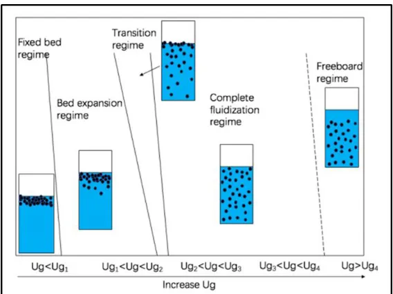
Figure 2-1 Upward gas-solid fluidized bed systems with increasing gas velocity ...14
Figure 2-2 Typical sketch of a CFB system...15
Figure 2-3 Typical radial flow structures in a CFB riser ...17
Figure 2-4 Typical axial flow structures in a CFB riser ...17
Figure 2-5 Flow structures in HDCFB riser and LDCFB riser ...17
Figure 2-6 Typical axial solids holdup profiles in HDCFB risers and LDCFB risers ...18
Figure 2-7 Typical radial distributions of solids holdup in a CFB downer ...19
Figure 2-8 Typical axial distributions of solids holdup in a CFB downer ...19
Figure 2-9 A typical schematic diagram of an inverse liquid-solid fluidized bed ...21
Figure 2-10 A typical sketch of an inverse liquid-solid circulating fluidized bed system 22 Figure 2-11 A typical sketch of a bubble-induced inverse gas-liquid-solid three-phase fluidized bed system ...23
Figure 2-12 A flow regime diagram of bubble-induced inverse three-phase fluidization system ...24
Figure 2-13 Radial trends of cluster size at (a) h/H≈0.2-0.3, (b) h/H≈0.5-0.6. ...29
Figure 2-14 Radial trends of cluster voidage at (a) h/H≈0.1, (b) h/H≈0.6-0.7...29
Figure 2-15: An overview of numerical attempts for cluster prediction ...31
Figure 2-16: Eight parameters and three scales of interaction in heterogeneous flow structure of CFB. ...35
xvii
Figure 3-2 Geometric structure at the inlet of the riser ...52
Figure 3-3 Gas distributor of the riser ...52
Figure 3-4: Meshes for the calculation domain in the testing riser...58
Figure 3-5 Inlet structure: (a): original inlet structure; (b): modified inlet structure ...60
Figure 3-6 Contours of solids phase volume fraction, Ug= 5m/s, Gs=100 kg/m2s ...63
Figure 3-7 Velocity vectors of the gas and solids at the entrance region of the CFB riser, Ug= 5 m/s, Gs=100 kg/m2s ...63
Figure 3-8 Contours of velocity of gas and solid phases at inlet, Ug= 7m/s, Gs=500 kg/m2s ...64
Figure 3-9 Velocity vector profile of the solid phase with the modified inlet boundary conditions at the entrance region of the CFB riser Ug= 7m/s, Gs=500 kg/m2s ...64
Figure 3-10 Contours of solids volume fraction at inlet, Ug= 7m/s, Gs=500 kg/m2s ...66
Figure 3-11 Velocity profiles of gas and solids phases at different heights ...67
Figure 3-12 Comparison of the solids holdup profiles at (a): h=4.81m; (b): h=7.35m (Ug=5 m/s, Gs=100 kg/m2s) ...68
Figure 4-1 Configuration of the CFB riser ...79
Figure 4-2 Mesh for the computational domain of the CFB riser ...79
Figure 4-3 Variations of the predicted bed pressure drop and solids mass flow rate at the outlet with time ...82
Figure 4-4 Comparison of the radial solids holdup profiles in the LDCFB and HDCFB at height = 7.35 m ...83
xviii
Figure 4-6 Axial solids holdup profiles under different superficial gas velocities ...84
Figure 4-7 Axial distributions of the solids holdup under different operating conditions.87 Figure 4-8 Local profiles of solids holdup at different heights (a) LDCFB (Ug = 7 m/s, Gs = 100 kg/m2s); (b) HDCFB (Ug = 7 m/s, Gs = 700 kg/m2s) ...88
Figure 4-9 Profiles of the axial velocities for gas and solids phases, and slip velocities between the gas and particles in the LDCFB and HDCFB (a) LDCFB; (b) Intermediate condition; (c) HDCFB...89
Figure 4-10 Local positions of ∆𝑉𝑝<2% in the CFB riser for the fully developed solids flow ...91
Figure 4-11 Axial solids holdup distribution in LDCFBs and HDCFBs ...93
Figure 4-12 Overall bed density of LDCFBs and HDCFBs ...93
Figure 4-13 Comparisons of the proposed index (I), experimental data, and CFD results ...96
Figure 4-14 3D map of the predicted overall bed density ...97
Figure 4-15 2D map of the predicted overall bed density ...97
Figure 5-1 Configuration of the CFB system ...105
Figure 5-2 Schematic diagram of the gas distributor and solids inlet of the downer ...105
Figure 5-3 Mesh of the computational domain ...105
Figure 5-4 Axial profiles of the solids holdup under Gs = 100 kg/m2s ...111
Figure 5-5 Axial profiles of the solid holdup in the 3 in downer under Ug = 5 m/s ...111
xix
Figure 5-7 Radial profiles of the solid concentration in the 3 in downer at different
superficial gas velocities under Gs = 100 kg/m2s ...112
Figure 5-8 Radial profiles of the solid concentration in the 3 in downer at different solids circulation rates under Ug = 5 m/s...112
Figure 5-9 Comparison of the axial solids holdup distributions between the CFD results and experimental data ...114
Figure 5-10 Comparison of the overall bed density between the CFD results and the results from the proposed correlation ...115
Figure 5-11 2D map of the predicted overall bed density in the downer reactor ...116
Figure 5-12 3D map of the predicted overall bed density in the downer reactor ...117
Figure 5-13 Sketch of the development of the solids flow ...118
Figure 5-14 Cross-sectional particle velocity along the downer (a) Ug = 5 m/s and (b) Ug = 7 m/s ...119
Figure 5-15 Cross-sectional slip velocity along the downer (a) Ug = 5 m/s (b) Gs = 100 kg/m2s ...120
Figure 5-16 Tendency of the lengths of the three stages in the downer under different operating conditions ...120
Figure 5-17 Comparison of the axial solids holdup profiles between the 3 in and 8 in downers ...122
Figure 5-18 Comparison of the radial solids holdup profiles between the 3 in and 8 in downers under dilute conditions (Ug = 5 m/s and Gs = 200 kg/m2s) ...122
xx
Figure 6-1 Sketch of a gas-solids fluidization system considering the existence of
clusters ...135
Figure 6-2 Schematic diagram of the cluster-driven drag model ...136
Figure 6-3 Drag force on a particle in ideal system and homogeneous dilute
suspension ...136
Figure 6-4 Configuration of the CFB riser ...144
Figure 6-5 Mesh for the computational domain of the CFB riser ...144
Figure 6-6 Comparison of the numerical results by commonly used drag models with the
experimental data for the radial solids holdup profiles ...149
Figure 6-7 Comparison of numerical results by different drag models with the experimental
data for the axial solids holdup profiles ...149
Figure 6-8 Comparison of the Radial solids holdup profiles from the cluster-driven drag
model and the Syamlal-O’Brien drag model ...151
Figure 6-9 Radial profiles of solids holdup from cluster-driven drag model ...151
Figure 6-10 Axial profiles of the solids holdup under different operating conditions ....152
Figure 6-11 Axial profile of the gas phase and solid phase velocities ...153
Figure 6-12 Comparison of the slip velocity from the Syamlal-O’Brien model and
cluster-driven model ...154
Figure 6-13 Comparison of the granular temperature from the Syamlal-O’Brien model and
cluster-driven model ...155
Figure 6-14 Numerical results from different cluster size by the proposed cluster-driven
drag calculation ...156
xxi
Figure 7-1 Configuration of the CFB riser ...168
Figure 7-2 Mesh for the computational domain of the CFB riser ...168
Figure 7-3 Schematic diagram of the cluster-driven drag model ...169
Figure 7-4 Solids holdup profiles in the radial direction at different heights of the CFB riser
...172
Figure 7-5 Velocity profiles of gas and particles in the radial direction at different heights
of the CFB riser (Ug = 7 m/s, Gs = 400 kg/m2s) ...174
Figure 7-6 Instantaneous solids holdup contours of the riser (Ug = 5m/s, Gs =
300kg/m2s) ...180
Figure 7-7 Comparison of the probability density distributions of the overall solids holdup
in the CFB riser (Ug=5m/s, Gs=400kg/m2s) by the cluster-driven drag model and the
Syamlal-O’Brien drag model ...181
Figure 7-8 Example of typical clusters at the bottom zone of the riser (h=1-3 m) ...183
Figure 7-9 Examples of typical clusters in the middle of the riser (h>5m) ...184
Figure 7-10 Probability distribution function (PDF) of the solids holdup in LDCFBs and
HDCFBs ...188
Figure 8-1 Schematic diagram of the liquid-solid inverse circulating fluidized bed ...196
Figure 8-2 Axial distributions of the cross-sectional average solids holdup for Cases #1-#3
...202
Figure 8-3 Axial distributions of the cross-sectional average solids holdup for Cases #4-#6
...203
xxii
Figure 8-5 Comparisons of the solids holdup radial distributions between the numerical
and experimental results at h=2.1m for Cases #1-#3 ...205
Figure 8-6 Radial distributions of solids holdup at different axial locations ...206
Figure 8-7 Comparisons of the solids holdup radial distributions between the numerical
results at different time and experimental results at h=2.1m and h=3.4m for Case #7 ...207
Figure 8-8 Velocity vector of the solids phase for Case #4 at t=232s ...207
Figure 8-9 Radial distributions of solids holdup at different axial locations ...208
Figure 8-10 Lateral velocities of particles at different bed heights for Cases #1-#3 ...210
Figure 8-11 Lateral velocities of particles at different bed heights for Cases #4-#6 ...210
Figure 8-12 Lateral velocities of particles at different bed heights for Cases #8 and #9 210
Figure 8-13 Axial velocities of particles at different bed heights for Cases #1-#3 ...211
Figure 8-14 Axial velocities of particles at different bed heights for Cases #8 and #9 ...211
Figure 8-15 The distributions of the average solids holdup along axis for Cases
#8-#10...212
Figure 8-16 The distributions of the average solids holdup along axis for Cases
#10-#12...212
Figure 8-17 Radial distributions of solids holdup at different axial locations for
Case#10 ...213
Figure 8-18 Radial distributions of solids holdup for Cases #10-#12 at h=3.22m ...214
Figure 8-19 Lateral velocities of P850 and P950 at different bed heights for Cases #10 215
Figure 8-20 Lateral velocities of P850 and P950 for Cases #10-#12 at h=3.22m ...215
xxiii
Figure 8-22 Axial velocities of P850 and P950 for Cases #10-#12 at h=3.22m ...216
Figure 9-1 Schematic diagram of gas-driven inverse gas-liquid-solid fluidized bed. ...225
Figure 9-2 Computational domain of the inverse three-phase fluidized bed under the batch
liquid mode ...233
Figure 9-3 Flow regime map in the bubble-induced inverse three-phase fluidized bed ..235
Figure 9-4 CFD contours of the solid phase volume fraction under different Ug with 15%
solids loading and ρs=930 kg/m3 ...236
Figure 9-5 Experimental results of the variation of the transition superficial gas velocities
with the solids loadings ...237
Figure 9-6 Comparison of the axial solids holdup profiles under different solids loadings
in the complete fluidization regime between the CFD results and experimental data...238
Figure 9-7 Experimental results of the variation of the transition superficial gas velocities
with particle densities at solids loading=15% ...239
Figure 9-8 CFD contours of the solid phase volume fractions for different particle densities
at Ug =15 mm/s and 15% solids loading ...239
Figure 9-9 CFD contours of the solid phase volume fraction VS. timeat Ug =15mm/s, 15%
solids loading, and ρs=930 kg/m3 ...241
Figure 9-10 Time averaged (t>200 s) radial velocity profile of the solid phase at different
heights at Ug =15mm/s, 15% solids loading, and ρs=930 kg/m3 ...241
Figure 9-11 Time averaged radial profile of the solid volume fraction at different heights
at Ug =15mm/s, 15% solids loading, and ρs=930 kg/m3 ...242
Figure 9-12 Time-averaged radial velocity profile of the solid phase and liquid phase at
H=1 m, Ug =15 mm/s, 15% solids loading, and ρs=930 kg/m3 ...243
xxiv
Figure 9-14 Radial velocity profiles of the solid phase under different Ug (a) H=1.5m; (b)
H=0.5m ...245
Figure 9-15 Instantaneous volume fraction contour (left) and particle velocity vector
contour (right) at (a) t=17 s (b) t = 60 s (c) t = 270 s ...247
Figure 10-1 Axial solids holdup distributions between gas-solid CFB riser (Ug = 5, 7 m/s,
Gs = 100, 400 kg/m2s) and downer (Ug = 5, 7 m/s, Gs = 100, 600 kg/m2s) ...254
Figure 10-2 The general idea on the system uniformity among various types of fluidized
1
Chapter 1
1
Introduction
Hydrodynamics and the underlying flow mechanisms of multiphase flows including
gas-solid, liquid-gas-solid, and gas-liquid-solid systems in various types of circulating fluidized
beds are studied via the computational fluid dynamic (CFD) approach in this work.
Numerical studies done on the wide range of fluidization systems and the data exchange
between the experimental and numerical studies provide more insight into the fundamental
studies of fluidization technology on a high-level and big-picture view.
The research background, objectives, and the structure of this thesis are briefly presented
in this chapter.
Background
Fluidization phenomenon is commonly seen in our daily life and has been applied in a wide
range of fields in industries over nearly a century since the first fluidized bed reactor was
developed for coal gasification in the 1920s (Kunii & Levenspiel, 1969). An efficient and
easy operation of granular materials can be achieved in a fluidized bed by introducing
fluids into the equipment at a certain velocity. Various types of fluidized bed reactors
operated under different conditions are designed for applications in many areas such as oil
refinery, coal combustion and gasification, particle coating, pharmaceutical processes, and
wastewater treatment (Jahnig, et al., 1980; Fan, et al., 1982 and Zhu & Cheng, 2005).
Since the 1970s, computational fluid dynamic (CFD) approach has become an effective
and more economic tool used for the research of fluidization phenomenon with the
development of computer science (Berruti & Kalogerakis, 1989; Gidaspow & Ding, 1990;
Sinclair & Jackson, 1989; and Tsuo & Gidaspow, 1990a). CFD modelling helps researchers
better understand the flow mechanisms in different types of fluidized beds and provides
more flow details when experimental measuring technology is limited. Nowadays, the fast
growth of computational energy makes numerical simulations to play a more significant
2
et al., 1993; Tsuo & Gidaspow, 1990b; Zhang, et al., 2015). In this work, CFD modelling
is used as the main approach for studying the flow structures of various fluidized beds.
During the development of fluidization technology, the most successful commercial
applications are found in the upward gas-solid fluidization process for gas-solid reactions
such as coal combustion and gasification or catalytic gas-phase reactions such as FCC
process (Horio, et al., 1992; Zhu & Cheng, 2005). As a result, the fundamental research
has focused on the gas-solid fluidized bed reactors since the 1920s revealing more details
in the hydrodynamics of the gas-solid flow in different types of fluidized beds and guiding
the following expansion of fluidization.
Over the years, fluidization technology went through many developments, from
velocity operation to high-velocity operation by increasing fluid velocity, and from
low-density operations to high-low-density operations by increasing solids flux (Bi & Grace, 1999;
Yerushalmi & Cankurt, 1979; Zhu & Bi, 1995). Furthermore, by changing the fluidizing
agent, the flow regime map of fluidization has expanded from gas-solid to liquid-solid and
gas-liquid-solid three-phase fluidizations (Li & Kwauk, 2003; Richardson & Zaki, 1997).
In addition, when lighter particles were used, inverse liquid-solid or gas-liquid-solid
three-phase fluidizations were developed by changing the particle or fluid properties (Fan, et al.,
1982; Karamanev & Nikolov, 1992).
During the operation of the fluidization process, solid particles will be suspended by the
pass-through fluid flow and will behave like a fluid after minimum fluidization, so that a
conventional low-velocity fluidized bed can be constructed for the batch operation of
fluidization. Further increasing the fluid velocity could lead to an entrainment of particles
at some point and a circulating fluidized bed (CFB) with the recycling of the entrained
particles was developed for high-velocity continuous fluidization operations in contrast to
the conventional low-velocity batch operations. A circulating fluidized bed system usually
consists of a riser and a downer where both the upward and downward fluidizations can be
operated respectively.
For gas-solid fluidization, by increasing gas velocity, the gas-solid fluidized beds can be
3
corresponding to conventional low-velocity operations, and circulating fluidized bed
corresponding to continuous high-velocity operations (Bai, et al., 1993; Grace, 1990; Horio,
et al., 1992; Ishii & Horio, 1991; Yerushalmi & Cankurt, 1979). Both conventional
fluidized beds and the circulating fluidized beds have been widely applied in industries
including chemical, food and pharmaceutical, mineral and energy processes (Jahnig et al.,
1980; Zhu & Cheng, 2005).
Under a high-velocity gas-solid fluidization operation, solids circulation rate (Gs) becomes
another important parameter affecting the overall flow structures together with the
superficial fluid velocity in a circulating fluidized bed. It has been pointed out that in a
gas-solid CFB riser, a higher gas-solids circulation rate results in a higher overall bed density and
distinct gas-solid flow structures from the low-density CFB riser. The high-density CFB
riser usually operates under a solids circulation rate higher than 400kg/m2s for Group A
particles has been distinguished as new type of fluidization operation from the low-density
CFB riser in 1995 (Grace, et al., 1999; Wang, et al., 2014; Zhu & Bi, 1995). A high-density
operation performed under higher gas velocity in a HDCFB riser makes it a very desirable
reactor for catalytic gas-phase reactions accompanying with quick catalyst deactivation
process such as the FCC process for its better gas-solid contacting and higher conversion.
However, severe particle clustering phenomenon is observed in CFB riser reactors due to
the hydrodynamic and cohesive effects. The existence of particle clusters aggravates the
non-uniformity of the gas-solid flow structure in the CFB riser and hampers the gas-solid
mass and heat transfers (Wang, et al., 2014a; 2014b).
With the disadvantages of the GSCFB riser reactor in mind, the GSCFB downer, which
used to only act as the solids recycling apparatus, was employed as a new type of fluidized
bed chemical reactor to provide a more uniform flow condition. In a gas-solid CFB downer
reactor, both gas and particles travel downward with a short developing region because
particles accelerate very fast due to gravity (Wang, et al., 2015). Less particle clusters are
found in the GSCFB downer and the gas-solid flow structure is uniform both axially and
radially with less back-mixing of gas and solids (Wang, et al., 2015). A short and uniform
residence time distribution of gas and solids in the GSCFB downer makes it more suitable
4
in the reaction are valuable. Although many of the fundamental research and experiments
have been carried out in gas-solid fluidization, the flow mechanisms under high-density
operations in CFB systems are still not fully studied due to the restriction of experimental
and measuring techniques. CFD approach can extend the research of high-density CFB
operations to some extremely dense conditions simply by simulation and provide better
understanding of the flow mechanisms.
Although the gas-solid circulating fluidization technology has been well utilized,
fluidization has expanded to liquid-solid circulating fluidization since the 1990s and shortly
afterwards into gas-liquid-solid three-phase fluidization (Fan, 1985; Razzak, et al., 2009;
2010; Renganathan & Krishnaiah, 2004). By changing the fluidizing agent from gas to
liquid, particles can uniformly disperse in the liquid flow and the above-mentioned particle
clustering phenomenon becomes insignificant in (gas)-liquid-solid fluidized beds.
Similar to the gas-solid CFB system, high-velocity operations can be achieved in a
circulating liquid-solid fluidized bed (LSCFB) and a circulating gas-liquid-solid
three-phase fluidized bed (GLSCFB) (Razzak et al., 2009). Traditional industrial applications
such as leaching and washing, adsorption and ion exchange, or some bioprocesses widely
take place in the LSCFB or GLSCFB when heavier particles are used. By changing the
particle density to be lower than the liquid density, the so-called inverse liquid-solid
fluidized bed (ILSFB) is developed in which both the solids and liquid flow downward
(Choi & Shin, 1999). In the inverse liquid-solid fluidized bed, light particles are initially
packed in the top of the reactor and then are fluidized and move downward by the by
downward flowing liquid. When the downward flowrate of the liquid is high enough,
entrainment of the particles also occurs and an inverse circulating fluidized bed (ILSCFB)
system is developed.
Gas bubbles also can be introduced in to the inverse liquid-solid fluidized bed reactor as a
fluidizing agent other than the liquid, leading to the bubble induced inverse gas-liquid-solid
three-phase fluidized bed reactor. Increasing interests from the biochemical fields
especially the area of wastewater treatment are found in the bubble induced inverse
5
particles and react with the wastewater with the movements of particles. Compared to the
upward gas-liquid-solid (GLS) three-phase fluidized bed reactor, the BIFB provides a more
flexible oxygen supply, less clogging of the biomass, reduced shearing effects to the
bio-film caused by liquid flow, and longer residence time of the liquid, with a lower or even
negligible liquid velocity under a homogeneous flow condition.
Currently, less modelling work has focused on the LSCFB and bubble induced GLSFB
most likely because of the lack of enough experimental data. However, the future
applications of these two new types of fluidized beds are very promising and CFD approach
is a helpful tool urgently needed in industrial design, optimization, and scale-up. Therefore,
in this work, reliable CFD models studying the hydrodynamics in a LSCFB and bubble
induced GLSFB needs to be developed respectively and validated with the experimental
data collected in the same group.
Additionally, numerical studies on fluidized bed reactors can be generally classified into
two approaches: the Eulerian-Lagrangian (EL) method and Eulerian-Eulerian (EE) method.
The Eulerian-Lagrangian (EL) method tracks the movements of every particle and less
assumptions are used, but costs more computational resources (Benyahia et al., 2000;
Hartge, et al., 2009; Tsuji et al., 1993; Van Der Hoef, et al., 2004; Zhou, et al., 2002; Zhu,
et al., 2008). The Eulerian-Eulerian (EE) method treats the particles as a secondary fluid
phase by coupling the kinetic theory of granular flow model for the solids phase so that it
is more desirable for simulations on large-scale fluidized bed equipment due to less
computational costs.
The numerical theories of the multiphase flow in fluidized beds employed many
simplifications and empirical correlations so that discrepancies are found between the
experimental and simulation results. Especially in gas-solids CFB systems in which the
existence of particle clusters cannot be ignored, the underlying physics in the gas-solids
interactions are not fully understood both experimentally nor numerically due to its
complexity. The particle clusters consists of a group of single particles with a denser solids
concentration than the surrounding dilute gas-solid suspension due to the hydrodynamic or
6
remarkable characteristics of a gas-solid CFB reactor, which results in the non-uniform
distributions of the solids holdup and particle velocity. The effects of clusters are usually
included in the drag calculation, which accounts for the gas-solids interactions in CFD
models (Agrawal, et al., 2001; Li et al., 2002; Syamlal & O’Brien, 1994; Tsuo & Gidaspow,
1990). Since the clusters have different properties from freely moving single particles such
as larger size and higher solids holdup, the ideal drag law for the dispersed particulate
system is longer applicable in a GSCFB. Knowing the existence of particle clusters, various
drag models are developed by researchers based on their own understanding of the
clustering phenomenon. Most of the current drag models were developed in the 1990s
when the experimental work on gas-solids fluidization hasn’t expanded to the high-density
operations. Therefore, the modified drag calculations which rely on the experimental
results mainly in the low-density operations appear to be not very accurately predict the
flow structures under high-density operations. Furthermore, with the development of
measuring techniques, more characteristics of clusters can be extracted and analyzed by
new approaches such as image processing by high-speed cameras and wavelet analysis of
the optical probe data. Therefore, properties of clusters can be statistically characterized
and were explicitly used into the calculation of the drag force in this work for the gas-solid
CFB system.
Research objectives
The overall objective is to comprehensively study the hydrodynamics and the underlying
flow mechanisms of the multiphase flows in various types of circulating fluidized bed
(CFB) systems under a wide range of operating conditions via computational fluid dynamic
(CFD) approach.
With the overall objective in mind, the following objectives are included:
To investigate the gas-solid flow structures in both the riser and downer reactors of a gas-solid circulating fluidized bed system via a validated CFD model. (Chapters 3, 47
To study the effects of the entrance geometric structure of the CFB riser on the
simulation results.
To compare the solids holdup distributions, particle velocity profiles both axially
and radially between the CFB riser and downer.
To study the transition phenomenon in the CFB riser and downer reactors from
dilute to dense flow conditions respectively.
To investigate the combined effects of the superficial gas velocity and solids
circulation rate on the overall bed density and local solids distribution between
low-density fluidization operations and high-low-density fluidization operations.
To develop a cluster-driven drag model, which directly employs the characteristics of particle clusters into the calculation of the drag force in a gas-solid CFB reactor withthe help of the image and wavelet analysis from the experimental data. (Chapters 6&7)
To validate the proposed cluster-driven drag model with the experimental data.
To obtain a better understanding of the effects of the clustering phenomenon on
gas-solids flows.
To give further parametric studies of the proposed cluster-driven drag model by
studying the effects of cluster size and density.
To develop a validated CFD model for an inverse liquid-solid circulating fluidized bed (ILSCFB). (Chapter 8)To study the effects of different superficial liquid velocity, solids circulation rate,
and particle types on the distributions of solids holdup and particle velocity in an
ILSCFB.
To compare the flow structures between the binary-particle system and the
8
To propose a three-phase Eulerain-Eulerian CFD model for the bubble-induced inverse gas-liquid-solid fluidized bed. (Chapter 9)To study the flow regimes under different gas velocities and the transitions between
the flow regimes in the bubble-induced inverse fluidized bed (BIFB) via both the
experimental and numerical works.
To study the instantaneous distributions solids and liquid in the BIFB by CFD
model.
To study the effects of different types of particles on the solids distribution and
transition gas velocity between the flow regimes in the BIFB.
Thesis structure
Chapter 1 provides a general introduction of this research work.
Chapter 2 gives a detailed literature review on the experimental and numerical work of
circulating fluidization systems, the clustering phenomenon in gas-solid circulating
fluidized bed, and the CFD treatments on the clustering effects.
Chapter 3 investigates the effects of inlet boundary conditions in CFD modeling on flow
structures inside circulating fluidized bed risers
Chapter 4 compares the hydrodynamics and flow structures between high-density and
low-density operations in a gas-solid CFB riser via numerical simulations.
Chapter 5 numerically studies the hydrodynamics and flow structures of low-density
conditions to high-density conditions in a gas-solid CFB downer. The scale-up effects in
the gas-solid CFB downer are also investigated via CFD approach.
Chapter 6 proposes a cluster-driven drag model for gas-solids circulating fluidized bed riser
by directly employing the properties of particle clusters into the calculation of the drag
9
Chapter 7 provides a detailed study of the clustering phenomenon in the gas-solid CFB
riser via the proposed cluster-driven drag calculation. The clustering effects of cluster size,
density, and slip velocity are discussed.
Chapter 8 numerically studies the hydrodynamics and flow structures in an inverse
liquid-solid circulating fluidized bed.
Chapter 9 develops a validated CFD model for the bubble-induced inverse gas-liquid-solid
three-phase model.
Chapter 10 presents the conclusions of this study and recommendations for the future work.
References
Agrawal, Loezos, Syamlal & Sundaresan (2001). The role of meso-scale structures in rapid
gas–solid flows. Journal of Fluid Mechanics, 445, 151–185.
Bai, Jin, & Yu (1993). Flow regimes in circulating fluidized beds. Chemical Engineering
& Technology: Industrial Chemistry‐Plant Equipment‐Process Engineering‐
Biotechnology, 16(5), 307–313.
Benyahia, Arastoopour, Knowlton, Ted & Massah. (2000) Simulation of particles and gas
flow behavior in the riser section of a circulating fluidized bed using the kinetic theory
approach for the particulate phase. Powder Technology, 112(1–2), 24–33.
Berruti & Kalogerakis. (1989). Modelling the internal flow structure of circulating
fluidized beds. The Canadian Journal of Chemical Engineering, 67(6), 1010–1014.
Bi & Grace (1999). Flow patterns in high-velocity fluidized beds and pneumatic
conveying. Canadian Journal of Chemical Engineering, 77(2), 223–230.
Choi & Shin (1999). Hydrodynamics study of two different inverse fluidized reactors for
the application of wastewater treatment. Korean Journal of Chemical Engineering, 16(5),
10
Cocco, Shaffer, Hays, Karri & Knowlton (2010). Particle clusters in and above fluidized
beds. Powder Technology, 203(1), 3–11.
Fan, Muroyama & Chern (1982). Hydrodynamic characteristics of inverse fluidization in
liquid-solid and gas-liquid-solid systems. The Chemical Engineering Journal, 24(2), 143–
150.
Muroyama and Fan (1985), Fundamentals of gas‐liquid‐solid fluidization. AIChE J., 31:
1-34.
Gidaspow & Ding (1990). A bubbling fluidization model using kinetic theory of granular
flow. AIChE Journal, 36(4), 523–538.
Grace (1990). High-velocity fluidized bed reactors. Chemical Engineering Science, 45(8),
1953–1966.
Grace, Issangya, Bai, Bi & Zhu (1999). Situating the high-density circulating fluidized bed.
AIChE Journal, 45(10), 2108–2116.
Hartge, Ratschow, Wischnewski & Werther (2009). CFD-simulation of a circulating
fluidized bed riser. Particuology, 7(4), 283–296.
Horio, Ishii & Nishimuro (1992). On the nature of turbulent and fast fluidized beds. Powder
Technology, 70(3), 229–236.
Ishii & Horio (1991). The flow structures of a circulating fluidized bed. Advanced Powder
Technology, 2(1), 25–36.
Jahnig, Campbell, Martin (1980) History of Fluidized Solids Development at Exxon. In:
Grace J.R., Matsen J.M. (eds) Fluidization. Springer, Boston, MA
Karamanev and Nikolov (1992), Bed expansion of liquid‐solid inverse fluidization. AIChE
J., 38: 1916-1922.
Kunii & Levenspiel (2013). Fluidization engineering. Elsevier
Li, Cheng, Zhang, Yuan, Nemet & Fett (2002). The EMMS model — its application,
11
Li & Kwauk (2003). Exploring complex systems in chemical engineering—the multi-scale
methodology. Chemical Engineering Science, 58(3–6), 521–535.
Luo, Wu, Yang, Fang & Fan (2015). High-fidelity simulation of the 3-D full-loop gas-solid
flow characteristics in the circulating fluidized bed. Chemical Engineering Science, 123,
22–38.
Razzak, Barghi & Zhu (2010). Axial hydrodynamic studies in a gas–liquid–solid
circulating fluidized bed riser. Powder Technology, 199(1), 77–86.
Razzak, Barghi, Zhu & Mi (2009). Phase holdup measurement in a gas–liquid–solid
circulating fluidized bed (GLSCFB) riser using electrical resistance tomography and
optical fibre probe. Chemical Engineering Journal, 147(2–3), 210–218.
Renganathan & Krishnaiah (2004). Liquid phase mixing in 2-phase liquid–solid inverse
fluidized bed. Chemical Engineering Journal, 98(3), 213–218.
Richardson & Zaki (1997). Sedimentation and fluidisation: Part I. Chemical Engineering
Research and Design, 75(3), S82–S100.
Sinclair & Jackson (1989). Gas-particle flow in a vertical pipe with particle-particle
interactions. AIChE Journal, 35(9), 1473–1486.
Stroh, Daikeler, Nikku, May, Alobaid, von Bohnstein, Epple (2019). Coarse grain 3D
CFD-DEM simulation and validation with capacitance probe measurements in a circulating
fluidized bed. Chemical Engineering Science, 196, 37–53.
Syamlal & O’Brien (1987). The derivation of a drag coefficient formula from
velocity-voidage correlations. Technical Note, US Department of energy, Office of Fossil Energy,
NETL, Morgantown, WV.
Tsuji, Kawagucchi & Tanaka (1993). Discrete particle simulation of a fluidized bed.
Powder Technology, 77(1), 79–87.
Tsuo & Gidaspow (1990). Computation of flow patterns in circulating fluidized beds.
12
Van Der Hoef, Van Sint Annaland, & Kuipers (2004). Computational fluid dynamics for
dense gas-solid fluidized beds: A multi-scale modeling strategy. Chemical Engineering
Science, 59(22–23), 5157–5165.
Wang & Zhu (2015). Axial solids flow structure in a high density gas–solids circulating
fluidized bed downer. Powder Technology, 272, 153–164.
Wang, Li, Zhu, Wang, Barghi & Zhu (2015). A comparison of flow development in high
density gas-solids circulating fluidized bed downer and riser reactors. AIChE Journal,
61(4), 1172–1183.
Wang, Zhu, Barghi & Li (2014a). Axial and radial development of solids holdup in a high
flux/density gas-solids circulating fluidized bed. Chemical Engineering Science, 108, 233–
243.
Wang, Zhu, Li & Barghi (2014b). Detailed measurements of particle velocity and solids
flux in a high density circulating fluidized bed riser. Chemical Engineering Science, 114,
9–20.
Yerushalmi & Cankurt (1979). Further studies of the regimes of fluidization. Powder
Technology, 24(2), 187–205.
Zhang, Lei, Wang, Xu & Xiao (2015). A numerical study of gas-solid flow hydrodynamics
in a riser under dense suspension upflow regime. Powder Technology, 280, 227–238.
Zhou, Flamant, Gauthier & Lu (2002). Lagrangian approach for simulating the gas–particle
flow structure in a circulating fluidized bed riser. Int. J. Multiphase Flow 28, 1801–1821.
28, 1801–1821.
Zhu, Zhou, Yang & Yu (2008). Discrete particle simulation of particulate systems: A
review of major applications and findings. Chemical Engineering Science, 63(23), 5728–
5770.
Zhu & Cheng (2005). Fluidized Bed Reactors and Applications. In Multiphase Flow
Handbook (p. 5.55-5.93).
Zhu & Bi (1995). Distinctions between low density and high density circulating fluidized
13
Chapter 2
2
Literature review
Introduction to fluidization systems
Fluidization process is widely applied not only in the industries but also in our daily life to
easily handle granular materials. A fluidized bed is an equipment for stationary packed
particles in a column to be blew-up or suspended and then can behave like liquid by
introducing a flowing fluid such as gas or liquid.
Various fluidization systems have been developed with the expansion of the fluidization
technology since the 1920s (Zhu & Cheng, 2005). By changing the fluid media, solid
particles can be fluidized either by a liquid like water or a gas like air to form a liquid-solid
or a gas-solid fluidization system, and even by both the gas and liquid to form a
gas-liquid-solid three-phase fluidization system (Fan, 1985). By changing the fluid velocity, the
fluidization system can be classified into a conventional low-velocity fluidized bed and a
high-velocity continuous fluidized bed with the increase in fluid velocity (Yerushalmi, et
al., 1976). Under the high-velocity operation, the entrainment of particles will occur
because the fluid flow rate is high enough. A circulating fluidized bed is developed if the
entrained particles are collected and recycled back to the column so that the continuous
operation of particles is accomplished (Reh, 1995). By changing the particle density,
inverse liquid-solid fluidized bed has been developed when lighter particles were used
(Fan, et al., 1982). Further introducing gas bubbles into the liquid-solid fluidized bed, a
bubble-induced inverse three-phase fluidized bed is developed (Fan, et al., 1982). By
changing the flow directions, a fluidized bed downer reactor with both the fluid and
particles flowing downward in the column is also developed for some quick reactions
(Zhang, et al., 2001). With the development of the fluidization technology, the expansion
of the fluidization map has provided various fluidized bed systems for different industrial
uses and also more extensive fundamental researches are needed especially by numerical
14
Gas-solids circulating fluidized bed systems
In upward gas-solids fluidization, the fluidized bed systems can be divided into the
conventional fluidized beds including the bubbling bed, slugging bed, and turbulent bed
corresponding to the low-velocity operations and the continuous high-velocity “fast”
fluidized bed which stands for the circulating fluidized bed riser operating under a gas
velocity beyond the transport velocity as shown in Figure 2-1 (Bi & Grace, 1995; Grace,
1990; Yerushalmi & Cankurt, 1979). Under the high-velocity operation, the circulating
fluidized bed (CFB) system has been successfully applied into many chemical processes
since the 1940s when the first CFB was constructed by Winkler because of its higher gas
throughput and the continuous handling of the solid materials (Zhu & Cheng, 2005).
Nowadays, the CFB system enjoys numerous applications in the industries including
gas-solids reactions such as coal combustion and gasification, gas phase catalytic reactions
such as fluid catalytic cracking (FCC) process, fine powder process such as pharmaceutical
coating and drug delivery, and some physical processes such drying (Zhu & Cheng, 2005).
15
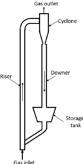
A circulating fluidized bed (CFB) system as shown in Figure 2-2 usually consists a riser
column where most of the chemical reactions take place in and a downer column which
used to be simply a returning pipe for the recycle of the particles and now becomes a reactor
in some cases for quick chemical reactions.
Figure 2-2 Typical sketch of a CFB system
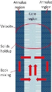
2.2.1 General flow structure in CFB risers
In a CFB riser reactor, both the gas and solid particles flow upward under a high gas
velocity so that less back-mixing of particles is achieved compared with the conventional
fluidized beds. The dilute phase plays the dominant role in the CFB riser which results in
a wide dilute core region of upward flowing solids suspension in the center of the riser
(Wang, et al., 2014a). On the other hand, a denser annular layer with higher solids holdup
exists in the wall region of the CFB riser due to the wall effects and more severe particle
clustering phenomenon near the wall (Ishii & Horio, 1991). Traditionally, the
above-mentioned radial gas-solid flow structure in a CFB riser is called a “core-annulus” flow
16
exponential or bottom-dense and upper-dilute as known as the “S shape” profile of the
solids holdup depending on the solids circulation rate and inventory in the standpipe as
shown in Figure 2-4. The non-uniform structures inside a CFB riser is due to the existence
of particle clustering phenomenon (Horio, et al., 1992). Particle clusters are a group or a
denser cloud of particles which are closely constrained and have an obviously higher local
solids holdup than the surrounding dilute suspensions due to the hydrodynamic effects or
cohesive effects (Cocco, et al., 2010). More details about the particle clusters inside a CFB
riser will be discussed in the next section.
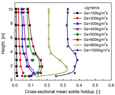
With increasing solids circulation rate, the CFB riser expands from low-density operation
to high-density operation. The hydrodynamics inside a low-density CFB (LDCFB) riser
and a high-density CFB (HDCFB) riser are quite different due to the increased overall
solids holdup as shown in Figure 2-5 (Wang, et al., 2014b). As a result, the high-density
CFB riser has been distinguished as a unique flow regime from the LDCFB riser since the
1995 (Zhu & Bi, 1995). In an HDCFB riser, the solid circulation rate is usually higher than
Gs = 400 kg/m2s leading to a higher overall bed density higher than εs = 0.05, which
contributes to a higher mass and heat transfer efficiency and more intensive gas and solids
contacting for a higher conversion (Wang, et al., 2014b). Fundamental studies revealed that
the dilute core region shrinks to be less than r/R = 0.5 in an HDCFB riser, in the meantime,
the wall layer of an HDCFB riser becomes wider and much denser, and even can reach a
local solids holdup as high as εs=0.05 under some extremely high solids fluxes (Wang, et
al., 2014b). Also, a longer bottom denser region with higher solids holdup is found in the
HDCFB riser due to the high Gs, however, sometimes the axial profile of solids holdup
could become exponential shape again with a much higher solids holdup from the entrance
of the riser to the top under the extremely high solids circulation rate (Gs ≥ 800 kg/m2s) as
shown in Figure 2-6 (Wang, et al., 2014b). The transition from LDCFB regime to HDCFB
regime was comprehensively studied by the detailed measurement of solids flux, particle
velocity, and radial and axial development of solids holdup in a macroscope view with the
help of the optical fiber probe (Wang, et al., 2014a; 2015a). However, more detailed flow
development from the microscope view and the effects of the underlying gas-solids
interactions to the formation of the particle clusters and the corresponding transition from
17
Figure 2-3 Typical radial flow structures in a CFB riser
Figure 2-4 Typical axial flow structures in a CFB riser
18
Figure 2-6 Typical axial solids holdup profiles in HDCFB risers and LDCFB risers
(Wang, et al., 2014a)
2.2.2 General flow structure in CFB downers
In contrast to the CFB riser reactor where the gas-solids suspension flows upwardly, a CFB
downer reactor in which both the gas and solids flow concurrently downward also shows
promising potential in some quick chemical reactions due to its much shorter and uniform
residence time distribution of gas and solids. The gas-solid flow structure becomes much
uniform in a CFB downer since the gas and particles flow with the same direction of the
gravity. Consequently, a much wider and more uniform dilute region which almost
occupies the whole cross-sectional area of the CFB downer with a slightly higher solids
holdup at the wall is found radially inside a downer as shown in Figure 2-7 (Wang, et al.,
2016). Axially, a much shorter entrance denser region below the gas distributor followed
by a uniform fully developed region along the downer is recognized in the downer reactor
as shown in Figure 2-8 (Wang, et al., 2015b). Since the gas and solids flow with the same
direction as the gravity, the acceleration of the gas and particles is very fast so that the slip
velocity between the gas and particles becomes smaller and there is almost no back-mixing
19
Figure 2-7 Typical radial distributions of solids holdup in a CFB downer (Wang et
al., 2016)
Figure 2-8 Typical axial distributions of solids holdup in a CFB downer (Wang et
al., 2015b)
Inverse liquid-solid and gas-liquid-solid fluidized bed
Inverse fluidization usually can be achieved in liquid-solid and gas-liquid-solid fluidized
bed systems where light particles with a density lower than liquid are used. Since the
particles are lighter than liquid, a downward flow of liquid is required to overcome the net
buoyancy of the particles and so that to fluidize them. Such type of fluidization operation