PARTNER
Advanced Communications System
Installation, Programming, and Use
Printed in USA
Notice
Every effort was made to ensure that the information in this book was complete and accurate at the time of printing. However, information is subject to change.
Federal Communications Commission Statement
This equipment has been tested and found to comply with the limits for a Class A digital device, pursuant to Part 15 of the FCC Rules. These limits are designed to provide reasonable protection against harmful interfer-ence when the equipment is operated in a commercial environment. This equipment generates, uses, and can radiate radio-frequency energy and, if not installed and used in accordance with the instructions, may cause harmful interference to radio communications. Operation of this equip-ment in a residential area is likely to cause harmful interference, in which case the user will be required to correct the interference at his own expense. This system is Class B compliant in some configurations. See the PARTNER Customer Support Document for additional FCC informa-tion.
Canadian Department of Communication (DOC) Interference Information
This digital apparatus does not exceed the Class A limits for radio noise emissions set out in the radio interference regulations of Industry Can-ada.
Le Présent Appareil Nomérique n’émet pas de bruits radioélectriques dépassant les limites applicables aux appareils numériques de la class A préscrites dans le reglement sur le brouillage radioélectrique édicté par le Industrie Canada.
Preventing Toll Fraud
“Toll fraud” is the unauthorized use of your telecommunications system by an unauthorized party (for example, a person who is not a corporate employee, agent, subcontractor, or working on your company’s behalf). Be aware that there may be a risk of toll fraud associated with your sys-tem and that, if toll fraud occurs, it can result in substantial additional charges for your telecommunications services.
The final responsibility for securing both this system and its networked equipment rests with you — an Avaya Inc. system administrator, your tele-communications peers, and your managers. Avaya Inc. does not warrant that this product or any of its networked equipment is either immune from or will prevent either unauthorized or malicious intrusions. Avaya Inc. will not be responsible for any charges, losses, or damages that result from such intrusions. For important information regarding your system and toll fraud, see the PARTNER Customer Support Document.
Avaya Fraud Intervention
If you suspect you are being victimized by toll fraud and you need techni-cal supporter assistance, techni-call the Avaya Customer Care Center at 1 800 628-2888.
Warranty
Avaya Inc. provides a limited warranty on this product. Refer to the “Lim-ited Use Software License Agreement” card provided with your package. For additional warranty information, see the PARTNER Customer Sup-port Document.
Trademarks
PARTNER, PARTNER MAIL VS, PARTNER MAIL, MLS-34D, MLS-18D, MLS-12D, MLS-12, MLS-6, MDC 9000, MDW 9000, MDW 9010, MDW 9030P, and SYSTIMAX are registered trademarks of Avaya Inc. in the U.S. and other countries.
Fax 1 800 457-1764 International Fax 410 891-0207
Write: GlobalWare Solutions 200 Ward Hill Avenue
Haverhill, MA 01835 USA Attention: Avaya Account Manager
Order: Avaya Publications Center Document No. 518-456-803 Issue 3, March 2002
For additional documents, refer to the PARTNER Customer Support Document.
Customer Support
If you need assistance when programming or using your system, con-tact your local Authorized Dealer or call the Avaya Customer Care Cen-ter at 1 800 628-2888. Consultation charges may apply.
Obtaining Products
See “Obtaining Products” in the PARTNER Customer Support Docu-ment.
Avaya Web Page
For information about Avaya products and service, go to
www.avaya.com. For product documentation for all Avaya products and related documentation for PARTNER ACS, go to www.avayadocs.com.
Heritage Statement
Intellectual property related to this product (including trademarks) and registered to Lucent Technologies Inc. has been transferred or licensed to Avaya Inc. Any reference within the text to Lucent Technologies Inc. or Lucent should be interpreted as reference to Avaya Inc. The excep-tion is cross references to books published prior to May 1, 2001, which may retain their original Lucent titles. Avaya Inc., formed as a result of Lucent's planned restructuring, designs, builds, and delivers voice, converged voice and data, customer-relationship management, mes-saging, multiservice networking, and structured cabling products and services. Avaya Labs is the research and development arm for the company.
Important Safety Instructions
The following list provides basic safety precautions that should always be followed when using your telephone equipment.1. Read and understand all instructions.
2. Follow all warnings and instructions marked on the product. 3. Unplug all telephone connections before cleaning. DO NOT use
liquid cleaners or aerosol cleaners. Use a damp cloth for cleaning. 4. This product should be serviced by (or taken to) a qualified repair
center when service or repair work is required.
5. DO NOT use this product near water, for example, in a wet basement location.
6. DO NOT place this product on an unstable cart, stand or table. 7. Never push objects of any kind into slots or openings as they may
touch dangerous voltage points or short out parts that could result in a risk of fire or electric shock. Never spill liquid of any kind on the product.
8. DO NOT use the telephone to report a gas leak in the vicinity of the leak.
DO NOT block or cover the ventilation slots or openings; they prevent the product from overheating. DO NOT place the product in a separate enclosure unless proper ventilation is provided. DO NOT place the product flat on a surface. The control unit must be wall-mounted.
SAVE THESE INSTRUCTIONS
Programming, and Use
Master Table of Contents
1
Overview
Welcome! ...
1-1
Structure of the Book ...
1-2
Features ...
1-3
Modes of Operation...
1-4
System Capacity ...
1-6
System Components...
1-8
2
Installation
Overview ...
2-1
Evaluating the Environment ...
2-2
Installing the Control Unit ...
2-4
Connecting Lines and Extensions...
2-16
The 1600 DSL Module ...
2-18
The 012E Module...
2-25
Installing the Cover ...
2-27
Installing Telephones ...
2-27
Connecting Auxiliary Equipment ...
2-34
3
Initial System Programming
4
Programming System Options
Overview ...
4-1
Abbreviated Ringing (#305) ...
4-2
Automatic Extension Privacy (#304) ...
4-2
Backup and Restore ...
4-3
Call Coverage Rings (#116 or #320) ...
4-7
Caller ID Programming ...
4-9
Call Waiting (#316) ...
4-14
Copy Settings (#399) ...
4-16
Dialing Restrictions and Permissions...
4-17
Dial Mode (#201) ...
4-25
Display Language (#303) ...
4-26
Distinctive Ring (#308) ...
4-26
External Hotline (#311) ...
4-27
Forced Account Codes ...
4-29
Groups of Extensions...
4-31
Hold Disconnect Time (#203) ...
4-37
Hotline (#603) ...
4-38
Intercom Dial Tone (#309) ...
4-39
Line Access Mode (#313) ...
4-40
Line Assignment (#301) ...
4-41
Line Coverage Extension (#208) ...
4-43
Outside Conference Denial (#109) ...
4-44
Pool Programming ...
4-44
Recall Timer Duration (#107) ...
4-49
Remote Administration Password (#730)
Transfer Return Programming ...
4-58
Unique Line Ringing (#209) ...
4-60
Voice Interrupt On Busy (#312) ...
4-61
5
Initial Telephone Programming
Overview ...
5-1
Required Telephone Programming ...
5-2
Automatic Line Selection...
5-2
Extension Name Display ...
5-4
Line Ringing ...
5-5
6
Using the Telephones
Overview ...
6-1
System Telephones ...
6-1
Single-Line Telephones ...
6-10
Display ...
6-13
Handling Calls ...
6-15
7
Operator Features
Overview ...
7-1
Programming an Operator’s Extension ...
7-1
Automatic System Answer Features ...
7-4
Direct Extension Dial Features...
7-10
Night Service Button (#503) ...
7-15
Outgoing Call Restriction Button (#114)...
7-17
Station Unlock (F22) ...
7-19
Wake Up Service Button (#115) ...
7-19
8
Programming & Using Telephone Features
Call Coverage (F20,XX,XX)–
Release 2.0 or Later ...
8-8
Call Forwarding/Call Follow-Me (F11,XX,XX) ...
8-11
Call Park ...
8-14
Call Pickup (I6XX) ...
8-15
Call Screening (F25)–Release 3.0 or Later ...
8-16
Caller ID Features ...
8-18
Conference Drop (F06) ...
8-26
Contact Closure (F41 and F42) ...
8-27
Direct Line Pickup Features ...
8-29
Do Not Disturb (F01) ...
8-32
Exclusive Hold (F02) ...
8-33
Extension Name Display ...
8-34
External Hotline ...
8-34
Group Calling–Ring/Page (I7G/I*7G) ...
8-35
Group Hunting–Ring/Voice Signal
9
Using Auxiliary Equipment
Overview ...
9-1
Tip/Ring Device Requirements ...
9-2
Combination Extensions ...
9-2
Answering Machines ...
9-4
Auto Attendant ...
9-7
Contact Closure Adjunct ...
9-9
Credit Card Scanners ...
9-12
Doorphone Programming...
9-13
Fax Machines ...
9-15
Loudspeaker Paging System ...
9-25
Modems ...
9-26
Music-On-Hold ...
9-28
Night Service with Auxiliary Equipment...
9-31
Station Message Detail Recording (SMDR)...
9-32
Voice Messaging Systems ...
9-40
10 Upgrading the System
Overview ...
10-1
Battery Replacement...
10-1
Using a PC Card ...
10-2
Upgrading 1600 DSL and 012E Module Firmware ...
10-6
Adding New Modules ...
10-7
Replacing Modules...
10-9
Changing Settings and Adding Lines, Pools, and Extensions ...
10-16
11 Troubleshooting
Overview ...
11-1
Customer Self Service Center
012E Module Power Management...
11-4
System Telephone Problems ...
11-5
Single-Line Telephone Problems ...
11-9
Other Telephone Problems ...
11-11
Problems with Combination Extensions...
11-16
Problems with Tip/Ring Devices ...
11-17
Problems with the 1600 DSL Module...
11-18
Problems with Automatic Backup ...
11-21
Problems with Manual Backup...
11-23
Problems with System Restore ...
11-25
System Problems ...
11-27
Other Problems with System ...
11-30
A
Cross-Reference of Features
B
Special Characters
Examples ...
B-2
C
Speed Dial Form
Speed Dial Form ...
C-1
D
Programming Mixed Telephone Types
Overview ...
D-1
E
Flow Charts
Contents
1
Welcome! . . .
1-1
Structure of the Book . . .
1-2
Features . . .
1-3
■
Features Available with Release 2.0 or Later . . .
1-3
■Features Available with Release 3.0 or Later . . .
1-3
■Features Available with Release 4.0 or Later . . .
1-4
■Features Available with Release 5.0 or Later . . .
1-4
Modes of Operation . . .
1-4
■
Key Mode . . .
1-5
■Hybrid Mode . . .
1-5
System Capacity . . .
1-6
System Components . . .
1-8
Welcome!
1
Welcome!
Welcome to the PARTNER® Advanced Communications System (ACS). This dynamic
communications system comes complete with intuitive call handling combined with a variety of features that give you the efficient and flexible system you need.
The system also supports a full line of system telephones, many with displays that show you programming and operation feedback. But don’t throw that old telephone away, because the PARTNER ACS includes support for many single-line telephones. And you can connect many auxiliary devices, such as fax machines, answering machines, modems, and credit card scanners, to the system.
The PARTNER ACS can operate in two modes, Key and Hybrid, and can also operate as part of a Centrex system. With the system in Hybrid mode, you can group lines into pools to provide faster routing of calls.
Structure of the Book
This book contains eleven chapters, which supply information as follows:
■ Chapter 1, Overview–briefly describes the features, modes of operation, system capacities, and system components.
■ Chapter 2, Installation–intended primarily for the technician, explains the physical installation of the control unit and the telephones.
■ Chapter 3, Initial System Programming–describes the programming the System
Administrator must do to get the system up and running. This chapter also explains how to use System Programming and Telephone Programming.
■ Chapter 4, Programming System Options–describes the programming of system features that the System Administrator can do.
■ Chapter 5, Initial Telephone Programming–explains the telephone programming required of the System Administrator.
■ Chapter 6, Using the Telephones–explains for the user and the System Administrator how to use the system telephones and single-line telephones, including the handling of calls.
■ Chapter 7, Operator Features–explains the programming and use of features specific to the operator positions at extensions 10 and 11. This chapter is intended for the System
Administrator and the operators.
■ Chapter 8, Programming & Using Telephone Features–describes the programming and use of features available to any user on the system.
■ Chapter 9, Using Auxiliary Equipment–intended primarily for technicians and the System Administrator, describes typical equipment that is supported by the PARTNER ACS, including voice messaging systems.
■ Chapter 10, Upgrading the System–explains how the system software and hardware can be upgraded as new modules and releases become available. This chapter is intended for technicians and the System Administrator.
■ Chapter 11, Troubleshooting–intended for both technicians and the System Administrator, describes possible problems with the system and the solutions to these problems.
This book also contains five appendices:
■ Appendix A, Cross-Reference of Features–contains a table cross-referencing the most commonly used features and tables of feature codes arranged numerically.
■ Appendix B, Special Characters–describes the unique characters entered via the dialpad into strings of dialed numbers.
■ Appendix C, Speed Dial Form–contains a form for users to enter both Personal and System Speed Dial numbers.
■ Appendix D, Programming Mixed Telephone Types–describes for the System Administrator how to program MLS telephones with a PARTNER telephone, and vice versa.
Features
Features
As each new version of system software is released, more valuable features become available.
Features Available with Release 2.0 or Later
■ Automatic System Answer to help answer and route calls.
■ Direct Extension Dial to allow callers to dial an extension or help group directly without the
aid of the receptionist.
■ Line Pooling to create up to four groups, or pools, of multiple outside lines. When users
access a pool to make a call, the system selects an available line from the pool.
■ Call Coverage for users who are unable to answer their calls but want their calls answered by
another individual.
■ Caller ID Logging and Dialing feature for users to view the names and numbers of logged
calls from system telephones. Users can press the Dial option to automatically dial the caller’s number.
■ SMDR Talk Time to allow you to track on an SMDR call report the length of time that users
talk on incoming outside calls.
Features Available with Release 3.0 or Later
■ Call Screening to listen to a caller leaving a message in the user’s mailbox.
■ Fax Calling Tone Detection to automatically route incoming fax calls to a fax machine.
■ Record-a-Call to record an active conversation in the user’s mailbox. PARTNER MAIL VS
Voice Messaging System (PMVS) 5.0 or later is required.
■ Unique Line Ringing for a user to differentiate which line is ringing.
■ Enhanced programmable features:
– Call Coverage Rings
– VMS Cover Rings
– VMS Hunt Delay
– VMS Hunt Schedule
■ Automatic Daylight Savings Time to change the time one hour as Daylight Savings Time
begins and ends.
■ 911 Calls do not require account code entry.
■ PARTNER Remote Access PC Card allows you to program the system remotely or locally from a PC and perform backup and restore functions.
Features Available with Release 4.0 or Later
■ Support of the 1600 DSL module, a module that contains up to 16 lines on one line jack.
■ Caller ID name and number appear on display telephones while a call is ringing.
■ Newly designed carrier, requiring no cover.
Features Available with Release 5.0 or Later
■ Support of the 012E module, a module that increases the maximum extension capacity to 48.
■ Support of the Endeavor 362EC module, enabling PARTNER® Endeavor telephones to function with PARTNER ACS.
■ Remote administration of the 1600 DSL module is available through the PARTNER ACS Remote Administration and Diagnostics PC software. For more information, see the PARTNER ACS Remote Administration and Diagnostics R5.0 Getting Started guide.
■ With the PARTNER ACS Remote Administration and Diagnostics PC software, the content of the PC Cards that are installed in the PARTNER ACS processor module as well as the modules installed in the carrier are displayed in an inventory screen. For more information, see the PARTNER ACS Remote Administration and Diagnostics R5.0 Getting Started guide.
■ Firmware upgrade capability of the 1600 DSL and 012E modulesis available by using a Remote Access PC Card or a Backup/Restore PC Card that is configured for the firmware upgrade.
Modes of Operation
The system supports two modes of operation. The mode of operation determines how users access outside lines from their telephones:
■ Key Mode. You access individual outside lines to make and receive calls.
■ Hybrid Mode.For Release 2.0 or later systems, you can access individual outside lines as in
Key mode. However, you also can create up to four groups, or pools, of multiple outside lines. When you access a pool to make a call, the system selects an available line from the pool. Since multiple lines are associated with the pool, you do not know which line within the pool is being used to make the call.
System mode is determined by the configuration of the processor module. The system is factory-set for Key mode. Changing to Hybrid mode requires a system programming change modifying the processor module. For more information about programming the mode of operation, see “Mode of Operation (#198)” on page 4-44.
Modes of Operation
Key Mode
When the system operates in Key mode, individual outside lines are assigned to users’ extensions for making and receiving calls. At extensions with system telephones, each individual line (Line 1, Line 2, Line 3, etc.) assigned to the extension is represented by its own line button. You can press any of the available line buttons on a system telephone to make outside calls. (Single-line
telephone users must dial 9 at intercom dial tone to make an outside call since their telephones do not have line buttons.)
With Key mode, you can easily join calls, since each line button can be labeled with a unique line number. For example, if you want to join a call on Line 2, you simply press the line button labeled “Line 2.” Key mode also lets you monitor call activity by using the lights next to the line button– anyone with a line assigned to his or her extension can tell when an incoming call is ringing on that line, when a call on that line is on hold, and when that line is in use.
At installation, the system assigns outside lines to the buttons on all system telephones from left to right, starting with the bottom row of buttons. On an extension basis, you can change which lines are assigned and which buttons are used to select the lines, if desired. All extensions in a system configured for Key mode are referred to as key extensions.
Hybrid Mode
Hybrid mode offers you flexibility in accessing outside lines from your telephone. As in Key mode, individual lines can be assigned to system extensions. Additionally, multiple outside lines can be grouped together in pools.The system can have up to four pools, including a main pool and three auxiliary pools. Each pool is identified by a pool access code–880, 881, 882, and 883
respectively.
Pools are represented on system telephones by pool buttons. Unlike line buttons, pool buttons give you access to multiple lines from a single button. Each auxiliary pool is associated with only one pool button. Since the main pool typically contains most of your company’s outside lines, it is associated with two pool buttons. This setup allows you to place a call by using one of the main pool buttons, place that call on hold, and make another call by using the second main pool button. Or you can establish a conference call by using lines in the main pool. The main pool and each auxiliary pool can be assigned to an extension, for a maximum of five pool buttons per extension.
System telephone users can press any of the available pool buttons on their telephones, or they can enter the pool access code at intercom dial tone to make an outside call. (Single-line telephone users must dial 9 or enter the pool access code at intercom dial tone to access a pool since their telephones do not have pool buttons.) After you press a pool button or enter a pool access code, the system selects a free line from the pool for you to make the call. You can access a pool as long as there is at least one available line in the pool.
In Hybrid mode, extension 10 always operates like an extension in Key mode. This means that every outside line in the system is associated with a specific line button at extension 10.
All other extensions can be set up with access to only lines, only pools, or a combination of lines and pools:
■ Those extensions that have pool buttons, even if they also have individual line buttons, are called pooled extensions.
■ Those extensions that have only line buttons (including extension 10) are called key extensions. Key extensions cannot access pools.
If your system is configured for Hybrid mode, keep in mind:
■ A line can be assigned to only one pool.
■ Individual extensions can be restricted access to specific pools.
■ Individual lines can be assigned to an extension with pool buttons as long as the lines are not part of any pool.
At installation, the system assigns all outside lines to the main pool and assigns the main pool to the two leftmost buttons on the bottom row of all system telephones, except extension 10. If desired, you can remove some of the lines from the main pool and create auxiliary pools. Then, you can assign pools and/or individual lines on a per extension basis.
System Capacity
The PARTNER ACS release you have, the carrier you use, and the combination of modules installed, determine the number of available lines and extensions:
■ PARTNER ACS Release 1.0 and 1.1 systems allow up to 15 lines and up to 32 extensions; however, these maximums cannot be achieved simultaneously.
Table 1-1. Release 1.0 and 1.1 Capacities
Configuration Maximum Lines Maximum Extensions
Stand-alone 3 lines, 8 extensions
PARTNER ACS processor module
8 extensions, 3 lines
PARTNER ACS processor module 2-slot carrier 7 lines, 8 extensions
Processor module, 400 module
14 extensions, 5 lines
Processor module, 206 module 5-slot carrier 15 lines, 20 extensions
Processor module, two 206 modules, two 400 modules
32 extensions, 11 lines
System Capacity
■ PARTNER ACS Release 2.0 or 3.0 systems allow up to 19 lines and up to 40 extensions; however, these maximums cannot be achieved simultaneously.
■ PARTNER ACS Release 4.0 or later systems allow up to 31 lines and up to 40 extensions; however, these maximums cannot be achieved simultaneously.
Table 1-2. Release 2.0 or 3.0 Capacities
Configuration Maximum Lines Maximum Extensions
Stand-alone 3 lines, 8 extensions
PARTNER ACS processor module
8 extensions, 3 lines
PARTNER ACS processor module 2-slot carrier 7 lines, 8 extensions
Processor module, 400 module
16 extensions, 6 lines
Processor module, 308EC module 5-slot carrier 19 lines, 8 extensions
Processor module, four 400 modules
40 extensions, 15 lines
Processor module, four 308EC modules
If you want to install a PARTNER Messaging or PARTNER MAIL VS module, keep in mind that the module uses one of the slots in the carrier, which reduces the system line and extension capacity.
Table 1-3. Release 4.0 Capacities
Configuration Maximum Lines Maximum Extensions
Stand-alone 3 lines, 8 extensions
PARTNER ACS processor module
8 extensions, 3 lines
PARTNER ACS processor module 2-slot carrier 19 lines, 8 extensions
Processor module, 1600 DSL module
16 extensions, 6 lines
Processor module, 308EC module
5-slot carrier 31 lines, 8 extensions
Processor module, 1600 DSL module, and three 400 modules
40 extensions, 15 lines
Processor module, four 308EC modules
System Components
Modular hardware design makes the system easy to install and expand. The most basic system consists of a PARTNER ACS processor module, which supports three lines and eight extensions. Using these lines and extensions, you can add optional devices and telephones to configure your system to meet your needs.
To expand the system to include more lines and extensions, simply attach additional modules and a carrier to contain them. The term “control unit” refers to the PARTNER ACS processor module and any other modules in the system.
WARNING:
There are no customer-serviceable components inside the system modules or carrier. There are hazardous voltages within that can cause severe or fatal personal injury. DO NOT OPEN THE MODULES.
■ PARTNER ACS Release 5.0 or later systems allow up to 31 lines and up to 48 extensions; however, these maximums cannot be achieved simultaneously.
Table 1-4. Release 5.0 or Later Capacities
Configuration Maximum Lines Maximum Extensions
Stand-alone 3 lines, 8 extensions
PARTNER ACS processor module
8 extensions, 3 lines
PARTNER ACS processor module 2-slot carrier 19 lines, 8 extensions
Processor module and 1600 DSL module
20 extensions, 3 lines
Processor module and 012E module
5-slot carrier 31 lines, 8 extensions
Processor module, 1600 DSL module, and three 400 modules
44 extensions, 19 lines Processor module, 1600 DSL module, and three 012E modules OR
48 extensions, 9 lines
Processor module, two 308EC modules, and two 012E modules
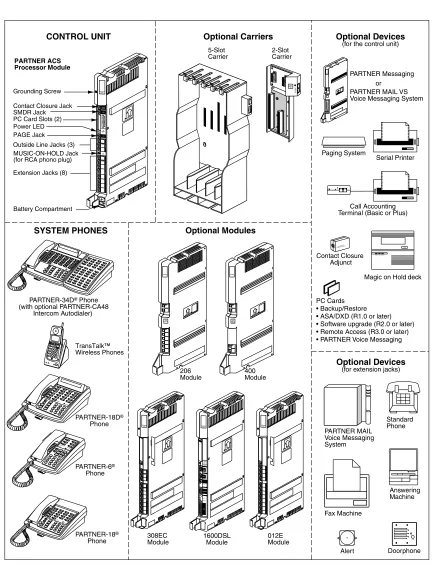
System Components
Configurations
You can install the PARTNER ACS system in one of three basic configurations, all of which must be wall-mounted:
■ Stand-alone PARTNER ACS processor module. This configuration does not use a carrier.
■ 2-slot carrier, which can hold the PARTNER ACS processor module and one other module.
■ 5-slot carrier, which can hold up to five modules, including the PARTNER ACS processor module. The processor module resides in the center slot.
Figure 1-1. System Configurations PARTNER 3000 PARTNER ACS Processor Module TransTalk™ Wireless Phones
PARTNER-34D® Phone
(with optional PARTNER-CA48 Intercom Autodialer)
PARTNER-6®
Phone SMDR Jack
Contact Closure Jack
5-Slot Carrier 400 Module 206 Module CONTROL UNIT
SYSTEM PHONES Optional Modules
PARTNER-18®
Phone
Optional Devices (for extension jacks)
Serial Printer
Magic on Holddeck
PC Cards • Backup/Restore • ASA/DXD (R1.0 or later) • Software upgrade (R2.0 or later) • Remote Access (R3.0 or later) • PARTNER Voice Messaging
Call Accounting Terminal (Basic or Plus)
Answering Machine Fax Machine Standard Phone Doorphone PUSH Alert Optional Devices (for the control unit) Optional Carriers PARTNER MAIL Voice Messaging System Paging System PAGE Jack
PARTNER PARTNER Messaging
or PARTNER MAIL VS Voice Messaging System
ABC
2DEF3 1
JKL
5MNO6
TUV
8WXYZ9 0 GHI 4 PQRS 7 * # Message Intercom IntercomExt. Conf Transfr Mic HFAI Hold Spkr Feature ABC 2 DEF 3 1 JKL
5MNO6 TUV 8WXYZ 9 0 GHI 4 PQRS 7 * # Feature Conf Transfr MicHFAI
Hold Spkr Intercom Interc om Ext. Message ABC 2 DEF 3 1 JKL
5MNO6
TUV
8WXYZ9 0 GHI 4 PQRS 7 * # Conf Transfr Mic HFAI Hold Spkr Feature Message Intercom Intercom Ext. ABC
2DEF3 1
JKL
5MNO6
TUV
8WXYZ9 0 GHI 4 PQRS 7 * # Conf Transfr Mic HFAI Hold Spkr Feature Message Intercom Intercom Ext. Contact Closure Adjunct PARTNER 3000 Contact Closure Adjunct
POWER PLAY RECORD PUSH
Extension Jacks (8) Grounding Screw
PC Card Slots (2) Power LED
Outside Line Jacks (3) MUSIC-ON-HOLD Jack (for RCA phono plug)
Battery Compartment L I N E S PFT E X T E N S I O N S PFT PARTNER MODULE206 L I N E S PFT PARTNER MODULE400 R1.0 L I N E S PFT 2-Slot Carrier SPAREHANDSET REFRESH On/Off Feat/P ConfGHI PQRS OPER Trans Hold Redial 12 4JKL ABC3DEF
System Components
System Modules
A system must contain a processor module. A 2-slot or 5-slot system also contains line/extension modules.
Processor Module
ThePARTNER ACS processor module provides the software intelligence that controls the system’s features. It has jacks for three outside lines, eight enhanced tip/ring extensions, a Music-On-Hold audio source, a loudspeaker paging system, a grounding screw, a jack that supports an adjunct for two Contact Closures, and a jack for a call reporting (SMDR) device, such as a printer. The processor module also has two PC Card slots, a two-color red and green light-emitting diode (LED), and two AAA user-replaceable batteries. The module provides support for integrated Caller ID information on system display telephones. The system requires one processor module.
Line/Extension Modules
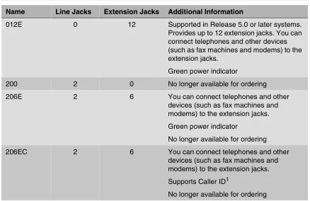
Table 1-5 shows the line/extension modules used in the PARTNER ACS.
Table 1-5. Line/Extension Modules
Name Line Jacks Extension Jacks Additional Information
012E 0 12 Supported in Release 5.0 or later systems.
Provides up to 12 extension jacks. You can connect telephones and other devices (such as fax machines and modems) to the extension jacks.
Green power indicator
200 2 0 No longer available for ordering
206E 2 6 You can connect telephones and other
devices (such as fax machines and modems) to the extension jacks. Green power indicator
No longer available for ordering
206EC 2 6 You can connect telephones and other
devices (such as fax machines and modems) to the extension jacks. Supports Caller ID1
Hereafter, references to 206 modules include 206E, 206EC, and all 206 modules used with previous releases of the PARTNER product line. Similarly, references to 400 modules include 400E, 400EC, and all 400 modules used with previous releases of the PARTNER product line. Any 200 modules can be used.
System Batteries
The system uses two user-replaceable AAA-size standard alkaline batteries in the processor module to ensure that system programming and telephone programming settings are not lost in case of a power failure.
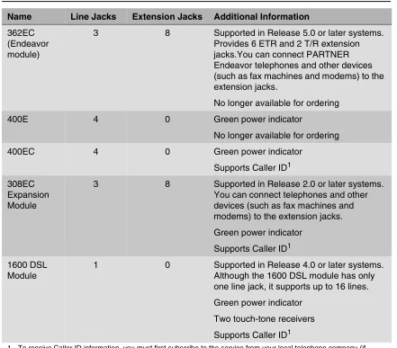
362EC (Endeavor module)
3 8 Supported in Release 5.0 or later systems.
Provides 6 ETR and 2 T/R extension jacks.You can connect PARTNER Endeavor telephones and other devices (such as fax machines and modems) to the extension jacks.
No longer available for ordering
400E 4 0 Green power indicator
No longer available for ordering
400EC 4 0 Green power indicator
Supports Caller ID1 308EC
Expansion Module
3 8 Supported in Release 2.0 or later systems.
You can connect telephones and other devices (such as fax machines and modems) to the extension jacks. Green power indicator
Supports Caller ID1 1600 DSL
Module
1 0 Supported in Release 4.0 or later systems.
Although the 1600 DSL module has only one line jack, it supports up to 16 lines. Green power indicator
Two touch-tone receivers Supports Caller ID1
1 To receive Caller ID information, you must first subscribe to the service from your local telephone company (if available) on a per-line basis. Then connect those lines associated with Caller ID to the line jacks on the module. Any users with system display telephones who receive calls on Caller ID lines will get Caller ID information.
Table 1-5. Line/Extension Modules–Continued
System Components
PC Card Slots
The processor module has two PCMCIA (Personal Computer Memory Card International
Association) interface slots (hereafter referred to as PC Card slots). You can buy PC Cards to use in these slots for the following purposes:
■ With Release 5.0 or later PARTNER ACS Remote Administration and Diagnostics PC software, the content of the PC Cards that are installed in the PARTNER ACS processor module as well as all modules installed in the carrier are displayed in an inventory screen.
■ Use a Backup and Restore PC Card to backup or restore telephone and system programming.
■ Use a PC Upgrade card. After powering down the system, you insert the PC Upgrade Card and turn the power back on. While the system upgrades, the bicolor (red/green) power LED on the processor flashes for about 20 seconds (40 seconds when a 1600 DSL module has been installed); then the power LED becomes steady green. If there is firmware on the PC Card that is downloaded to the module, then it will take longer for the power LED to become steady green. All of your system and extension programming is saved and ready to work with the new release.
■ Use a PC Card to store Automatic System Answer and Direct Extension Dial (ASA/DXD) messages. You can insert the card in either PC Card Slot of the processor module, Release 2.0 or later.
■ For PARTNER ACS Release 1.1 or later, use a PARTNER Voice Messaging PC Card to provide messaging features (store personal greeting and store and retrieve callers’ messages) for up to four mailboxes.
■ The PARTNER ACS Release 3.0 or later includes a PARTNER Remote Access PC Card, which allows you to program the system remotely or locally from a PC and perform backup and restore functions. You also can use the PARTNER Remote Access PC Card to upgrade previous versions of PARTNER ACS to the current release. In order to program the system remotely, you must have additional PARTNER Remote PC Software which is available from your Avaya representative or authorized dealer.
For complete information on installing PC Cards, see the instructions that came with the card.
Telephones
The telephones supported by the PARTNER ACS fall into two categories:
■ System telephones–telephones specifically designed to work with the PARTNER ACS
System Telephones
System telephones include the following:
■ PARTNER telephones – PARTNER-34D – PARTNER-18D – PARTNER-18 – PARTNER-6
■ MLS telephones
■ MLC-6
■ TransTalk© 9000-series wireless telephones
Available in Release 5.0 or later, PARTNER ACS supports PARTNER Endeavor telephones when an Endeavor 362EC module is installed in the carrier. The Endeavor telephones include:
■ PARTNER Endeavor-34D
■ PARTNER Endeavor-18D
■ PARTNER Endeavor-18
■ PARTNER Endeavor-6
Only the PARTNER telephones are discussed in this guide (see Chapter 6, “Using the
Telephones”). For information about an MLS, MLC, TransTalk 9000-series, or PARTNER Endeavor telephone, refer to the documentation that came with the telephone.
Intercom Autodialers
PARTNER telephones support the PARTNER-CA48 Call Assistant Intercom Autodialer at extensions 10 and 11. The autodialer provides Auto Dial buttons for all of the extensions in your system. The status lights next to each button also indicate calling activity at that extension. You can program the Auto Dial buttons for either intercom ringing, voice signaling, or manual
signaling. (Each user can have only one Auto Dial button–either on the system telephone or on the autodialer–for another extension in the system.) The Auto Dial buttons allow you to dial, signal, or transfer calls to system extensions with one touch.
Single-Line Telephones
You can also use industry-standard single-line rotary or touch-tone telephones, including feature telephones with built-in feature buttons and lights, with the system. Certain single-line telephones are recommended because of their compatibility with the Message Waiting Light capability of the system.
System Components
Auxiliary Equipment
You can connect many types of telecommunications devices to your system without expensive adapters or additional telephone lines–for example, answering machines, credit card scanners, and fax machines. Many industry-standard, tip/ring devices work with the system regardless of the manufacturer.
Auxiliary equipment also includes voice messaging systems. The following are supported by the PARTNER ACS:
■ PARTNER Messaging
■ PARTNER MAIL VS (PMVS)
■ PARTNER Voice Messaging (PVM) PC Card
■ The PARTNER MAIL system
Contents
2
Overview . . .
2-1
Evaluating the Environment . . .
2-2
Installing the Control Unit . . .
2-4
■
Wall-Mounting the Control Unit . . .
2-4
■Labeling Jacks . . .
2-9
■Grounding the System . . .
2-11
■Inserting Batteries in the Processor Module . . .
2-11
■Initializing the System . . .
2-13
■Checking the LEDs . . .
2-15
Connecting Lines and Extensions . . .
2-16
The 1600 DSL Module . . .
2-18
■
Programming Connections for the 1600 DSL Module . . .
2-19
■Initial Configuration of the 1600 DSL Module . . .
2-19
The 012E Module. . .
2-25
■
Placement Within the Carrier . . .
2-25
■Physical Design . . .
2-26
Installing the Cover . . .
2-27
Installing Telephones . . .
2-27
Overview
2
Overview
This chapter explains how to install the PARTNER® Advanced Communications System (ACS) Release 4.0 or later, unless otherwise specified.
The installation of the PARTNER ACS involves the following:
■ Evaluating the environmental requirements
■ Installing the control unit
■ Connecting lines and extensions
■ Installing telephones
■ Connecting auxiliary equipment
Evaluating the Environment
Before you begin the physical installation of the system, you must check that all environmental factors are within the acceptable ranges, as shown in Table 2-1.
Table 2-1. Environmental Requirements
Specification Value
Environmental Requirements-Control Unit
■ Mount on a wall at least 2 feet (0.6 meters) from the floor (wall mounting required)
■ Locate within 5 feet (1.5 meters) of the network interface jacks and a properly grounded electrical outlet not controlled by a switch, using supplied 7-foot (2.1-meter) cords
■ Operating temperature 32° to + 104°F (0° to + 40°C), not in direct sunlight
■ Humidity 15%-90%, noncondensing
■ For proper ventilation and easy replacement of modules, provide the following minimum clearance around the control unit:
– 5-slot carrier: 1 foot (0.3 meter) clearance at the top and sides and 2 feet (0.6 meter) at the front and bottom
– 2-slot carrier or Stand-alone ACS processor module: 1 foot (0.3 meter) clearance at the front, top and right side, and 2 feet (0.6 meter) at the bottom and left side
■ Locate in an area free of excess moisture, corrosive gases, dust, and chemicals
Electrical Requirements-Control Unit
■ U.S. and Canada: 90-264 VAC, 47-63 Hz, 3-prong outlet separate ground, separately fused at 15 Amps
■ Other countries: 90-264 VAC (220 VAC fused at 10 Amps)
■ Grounding to comply with Underwriters Laboratories (UL) 1459:
a. An insulated grounding conductor that is not smaller in size and equivalent in insulation material and thickness to the grounded and ungrounded branch circuit supply conductors, except that it is green with or without one or more yellow stripes, is to be installed as part of the circuit that supplies the product or system b. The grounding conductor mentioned in item A is to be connected
to ground at the service equipment
Evaluating the Environment
Specification Value
Requirements for
Out-of-Building Installations
■ Installation of a telephone or other standard (tip/ring) device in another building requires the following In-Range-Out-Of-Building (IROB) protectors to protect the control unit and device from electrical surges: – System phone: two IROB protectors
– Standard phone: two IROB protectors plus one carbon block protector
■ Installation of a Contact Closure Adjunct controlled device outside the building requires a 146G Surge Protector-SCL/8 to protect the control unit from electrical surges
Wiring ■ System phones: SYSTIMAX® Bulk Nonplenum (DIW) cable, SYSTIMAX
Bulk Plenum (HALAR/HALAR) cable, or at least 2-pair (4-wire) star (“home run” not “loop”)
■ Other standard telecommunications equipment (single-line phones, fax machines, answering machines, etc.): 1-pair (2-wire) D2R mounting cords recommended
■ Bridging adapter: 267F2
■ Range: 1,000 feet (305 meters) for system phones; 3,000 feet (915 meters) for standard devices
Safety Requirements
■ U.S.: Meets UL 1459 Issue 2 – Class 2 power standards:
UL 1012 Standard for Safety — Power Supplies
UL 1310 Standard for Safety — Direct Plug-in Transformers UL 1585 Standard for Safety — Class 2 and Class 3 Transformers
■ Canada: Meets CSA C22.2, No. 0.7-M1985
Installing the Control Unit
The stand-alone processor module or a carrier and its modules are referred to as the control unit. The control unit must always be wall-mounted.
WARNING:
There are no customer-serviceable components inside the system modules or carrier. There are hazardous voltages within that can cause severe or fatal personal injury. DO NOT OPEN MODULES.
Wall-Mounting the Control Unit
Before installing the system, be sure you read the safety instructions in the front of this guide.
To install the control unit, you must do the following:
■ Wall-mount the control unit.
■ Label the jacks.
■ Ground the system.
■ Insert the batteries into the processor module.
■ Initialize the system.
■ Check the LEDs on the modules.
The PARTNER Advanced Communications System can be installed in one of three configurations:
■ Stand-alone PARTNER ACS processor module
■ 2-Slot Carrier, which can hold up to two modules
Installing the Control Unit
Wall-Mounting a Stand-Alone Processor
Module and a 2-Slot Carrier
Install the processor module within 5 feet (1.5 meters) of a properly grounded wall outlet (not controlled by a switch) and the network interface jacks.
Follow these steps to wall-mount the module(s): 1. Using the enclosed template, mark the screw
locations on the wall.
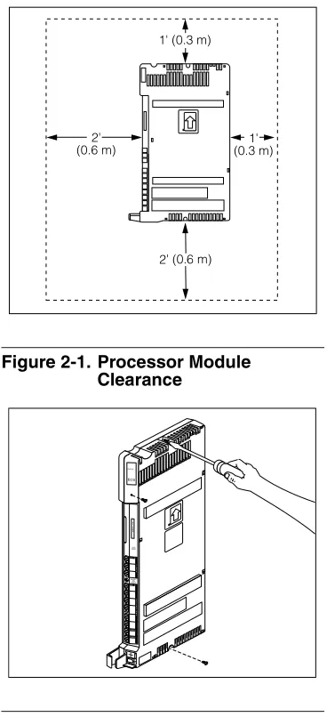
2. Hold the processor module against the wall with the line and extension jacks facing left. Leave at least 1 foot (0.3 meters) clearance at the top, front, and right side, and at least 2 feet (0.6 meter) at the bottom and left side
(see Figure 2-1). This allows you to access the jacks or expand the system with another module, and ensures adequate ventilation.
Figure 2-1. Processor Module Clearance
3. Insert a #8 sheet metal screw into the screw hole at the top of the processor module (see Figure 2-2).
4. If you are installing a second module, go to Step 5. If you are not installing a second module (stand-alone configuration):
a. Insert another #8 sheet metal screw into the screw hole at the bottom of the module. b. Tighten the screws until the mounting
tracks are snug against the wall. There must be a 3/8 inch (1 cm) gap between the wall and the rest of the module. Do not overtighten the screws or the module will warp and fail to operate.
c. Go to the next procedure, “Labeling Jacks” on page 2-9.
Figure 2-2. Screwing in a Processor Module
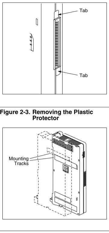
5. Remove the clear plastic protectors from the connectors on the right side of the wall-mounted PARTNER ACS processor module and the module to be added by grasping the tabs on the ends of the protector and lifting (see Figure 2-3).
Figure 2-3. Removing the Plastic Protector
6. Slide the second module onto the PARTNER ACS processor module, making sure the mounting tracks interlock (see Figure 2-4).
Figure 2-4. Module Mounting Tracks
7. Attach the 2-slot carrier to the top right side of the two modules (see Figure 2-5), properly engaging the connectors on the modules to the carrier.
Figure 2-5. Attaching the 2-Slot Carrier
Tab
Tab
Mounting Tracks
PARTNER
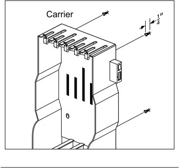
Installing the Control Unit 8. Fasten the carrier to the modules by using the
two #4 screws included with the carrier (see
Figure 2-6).
Figure 2-6. Fastening the 2-Slot Carrier
9. Insert the 3-1/2 inch #8 screw into the bottom of the modules (see Figure 2-7). Tighten it until the mounting tracks of the PARTNER ACS processor module are flush against the wall. Do not overtighten or the module will warp. Then go to the next procedure, “Labeling Jacks” on page 2-9.
Wall-Mounting a 5-Slot Carrier and Modules
Install the 5-slot carrier within 5 feet (1.5 meters) of a properly grounded wall outlet (not
controlled by a switch) and the network interface jacks. When you mount the carrier on the wall, leave at least 1 foot (0.3 meter) of clearance at the top and sides, and 2 feet (0.6 meter) at the front and bottom to ensure proper ventilation.
For a 5-slot carrier, you need four #12 screws of the appropriate type for the wall and weight of the control unit (a control unit with four expansion modules and a processor module weighs approximately 31 pounds or 14 kilograms). The weight of other configurations may vary slightly. Follow these steps to wall-mount the 5-slot carrier
and modules:
1. Using the enclosed template, mark the screw locations on the wall (see Figure 2-8). If you are mounting the carrier on plywood, start four #12 screws supplied with the carrier, leaving the screw heads extending approximately 1/4 inch (0.64 cm) from the wall. If you are mounting on drywall, use wall anchors, which must be purchased separately.
Figure 2-8. Mounting Screw Locations
2. Before installing any modules, make sure the clear, plastic protector has been removed from the connector area on the rear of each module. To remove the protector, grasp the tabs on the ends of the protector and lift (see Figure 2-9). 3. Insert the PARTNER ACS processor module in
the center slot of the carrier.
Figure 2-9. Removing the Plastic Protector
The location of each module within the carrier is important; place the modules as instructed in the following procedure.
1 4"
Tab
Installing the Control Unit
Labeling Jacks
After you have mounted the control unit on the wall, you must label the line and extension jacks. The line jacks are on the top of the modules, and the extension jacks on the bottom
(see Figure 2-11).
4. In the other slots, from left to right, first install the 1600 DSL module, then the 012E, 308EC, or 206 modules, followed by the 400 or 200 modules and/or a PARTNER Messaging or PARTNER MAIL VS module. Align the module carefully in the appropriate slot. For proper engagement of the connectors, the module must be inserted straight into the carrier (see
Figure 2-10). Once the module is properly seated, firmly push the center of the module until the connectors on the module lock into place. A slight click indicates the connectors are engaged.
Figure 2-10. Inserting a Module
If you use a 1600 DSL module, it must be in the first slot on the left. The 012E, 308EC, and 206 modules must be to the left of any 400 and 200 module.
PARTNER ACS Release 5.0 supports Endeavor telephones when an Endeavor 362EC module is installed in the carrier. Install the Endeavor 362EC module(s) to the right of the 1600 DSL module, if one is installed, and to the left of all 400 and 200 modules.
In Release 5.0, the system extension maximum is 48. However, in some configurations, the 012E module and/or the PARTNER Messaging module will physically permit more than 48 stations to be installed in the 5-slot carrier. In these configurations, only station ports and voice messaging ports up to 48 will function. Station ports and voice messaging ports above 48 will not function with ETR or T/R telephones because they are outside the PARTNER ACS dial plan.
CAUTION:
Do not force the module. Use the carrier shelf as a reference and do not tilt, slant, or rotate the module. If the module does not insert easily, remove it, clear any
obstruction, and reinsert it.
Carrier Shelf
YES
Carrier Shelf
Figure 2-11. Labeling Jacks
Follow these steps to label the line and extension jacks:
1. Label the line jacks on the processor module, beginning with “1” at the top line jack. 2. Do one of the following:
a. For a 2-slot carrier, label the line jacks on the other module.
b. For a 5-slot carrier, label the line jacks on the other modules by starting with the leftmost module and ending with the rightmost module.
3. Label the extension jacks on the processor module, beginning with “10” at the topmost extension jack.
4. Do one of the following:
a. For a 2-slot carrier, label the extension jacks on the other module.
b. For a 5-slot carrier, label the extension jacks on the other modules by starting with the leftmost module and ending with the rightmost module.
The 1600 DSL module is assigned 16 lines, even though it has only one line jack. If you have a 1600 DSL module in a 5-slot carrier, label the line jacks on the module after the 1600 DSL module to begin with “20.”
Installing the Control Unit
Grounding the System
Inserting Batteries in the Processor Module
The processor module uses two AAA-size standard alkaline batteries to guard against the loss of system programming in case of a power failure for 45 days to six months, depending on the freshness of the batteries. You should replace the batteries every year.
CAUTION:
Batteries and battery cover are packaged in a separate box. If you are replacing batteries, the old batteries must be removed with the power on or the system’s memory will be lost. You ground the system by running a solid copper wire from the processor module to an appropriate earth ground. Follow these steps to ground the system:
1. Attach one end of a #12 AWG or #14 AWG solid copper wire to the grounding screw on the processor module (see Figure 2-12). The length of the wire must not exceed 35 feet (7.6 meters). 2. Route the wire through the wire manager on the
front of the module.
3. Attach the other end of the wire to the approved earth ground, such as building steel or a cold water pipe.
Figure 2-12. Grounding Screw
In Release 4.0 and later systems, the configuration of the 1600 DSL module is not backed up to the PCMCIA card. Instead, the configuration is retained in the flash memory of the 1600 DSL module.
Follow these steps to insert the batteries:
1. Locate the battery compartment at the bottom of the PARTNER ACS processor module, below the extension jacks.
2. Push gently on the battery icon (the locking latch) and slide the battery icon up to cover the plus icon; this unlocks the battery assembly (see Figure 2-13).
3. Remove the battery assembly by gently pulling the tab at the bottom of the battery compartment cover.
Figure 2-13. Locked and Unlocked Positions
4. Insert two new AAA-size standard alkaline batteries into the metal battery clips by pushing them straight in, placing the negative (—) end of one battery into the bottom clip and the positive (+) end of the other battery into the top clip (see Figure 2-14).
Figure 2-14. Inserting the Batteries
Unlocked Position Locked
Position
Installing the Control Unit
Initializing the System
5. With the locking latch in the unlocked position (battery icon and “minus” icon visible), slide the battery assembly into the processor module along the battery guides on the inside of the battery compartment (see Figure 2-15). Push the battery assembly in far enough that the edges of the assembly slip behind the plastic housing of the processor module.
Figure 2-15. Sliding the Battery Assembly into the Processor Module
6. Pressing lightly on the battery icon on the front of the battery assembly, slide the locking latch downward to secure the assembly in place. The “plus” icon and the battery icon should now be visible on the front of the battery assembly (see Figure 2-13).
To initialize the system, you must insert any PC Card before powering up the system. The supported PC Cards are the Backup/Restore card, Automatic System Answer/Direct Extension Dial (ASA/DXD) card, PARTNER Voice Messaging Basics card, PARTNER Remote Access PC Card (Release 3.0 and later systems), and software upgrade card.
Follow these steps to initialize a system:
1. If your PC Card comes with a write-protect tab, verify that the write-protect tab on the PC Card is not in the write-protected position. If it is, use a paperclip or another pointed object to push the write-protect tab on the end of the PC Card upward to the nonprotected position.
2. To insert the PC Card, hold it with the label facing to the right, and slide it gently into one of the PC Card slots on the processor module. When inserted properly, the PC Card projects about 1-5/8” (4 cm) from the module.
3. If you have a 5-slot carrier, make sure the carrier’s On/Off switch is at the Off (“O”) position.
Tab Locking Latch
4. Press the power cord firmly into the power jack on the carrier or the stand-alone processor module until the cord locks into place (see Figure 2-16). 5. Plug the other end of the power cord into a
properly grounded three-prong wall outlet that is not controlled by a switch.
6. If you have a 5-slot carrier, move the On/Off switch to the On (“–”) position.
CAUTION:
The power cord should hang straight down from the connector for the entire length of the module or carrier. Do not install the power cord at an angle to the case or with a loop in it.
7. If this is the initial installation for a Release 3.0 system, follow these additional steps:
a. Check the LEDs to make sure that the processor is on steady green for at least 15 seconds.
b. Press
f00ss#
989
at extension 10 or 11.c. Press
25327
.The system resets. You may proceed with the rest of the installation upon
completion of the reset (about 20 seconds).
Figure 2-16. Attaching the Power Cord
Stand-Alone
2-Slot
Installing the Control Unit
Checking the LEDs
If your system has a 1600 DSL module, initialization of the line and extension ports may take up to 40 seconds. The initialization of the 1600 DSL module itself may take from 2 to 7 minutes.
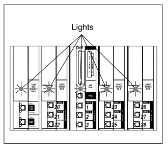
After you power up your system, check the green lights on the fronts of the modules (see Figure 2-17):
■ If a single light is out, power down the control unit, reseat the module, and then power up the carrier.
■ If multiple lights are out, power down the control unit, reseat either both modules (2-slot carrier) or the leftmost module that has a light out (5-slot carrier), and then power up the carrier.
If the lights are still out, see the Customer Support Document on the accompanying compact disc for information about whom you should contact.
Figure 2-17. Module LEDs
1 2 3
23 24 25
26 27 28 20
21 22
Connecting Lines and Extensions
If extensions are not wired to any modular jacks, call a qualified service technician.
Use the following procedure to connect lines and extensions:
1. Test for a dial tone at the network interface jacks before connecting outside lines to the control unit. For the test, connect a tip/ring telephone to the first network interface jack. a. Lift the handset and listen for a dial tone. (If there is no dial tone, contact your local
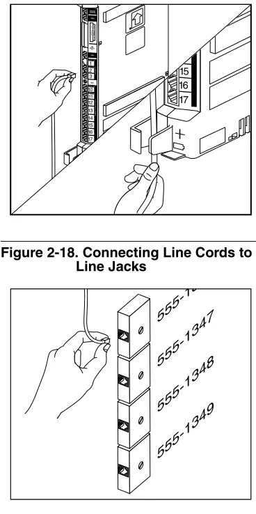
telephone company before continuing.) b. Repeat for each network interface jack. 2. Connect line cords to the line jacks on the
modules. Start at the top with the line jacks on the processor module, and then move to the leftmost module. Fill each module before moving to the next module to the right (see Figure 2-18).
3. Route each cord through the wire manager on the front of the module (see Figure 2-18).
Figure 2-18. Connecting Line Cords to Line Jacks
4. Connect the free end of each line cord to the appropriate network interface jack
(see Figure 2-19).
5. Test the lines by plugging a system telephone into extension jack 10. Press the line button for each outside line and listen for a dial tone. 6. Test the extensions by doing the following:
a. Plug a system telephone into the first extension jack on each module.
b. Press the line button on the telephone for each outside line and listen for a dial tone.
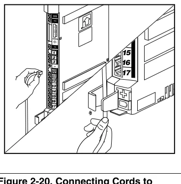
Connecting Lines and Extensions 7. Connect modular telephone cords to the
extension jacks, starting at the top extension jack on the processor module
(see Figure 2-20). When that module is full, move to the leftmost module. Fill each module before moving on to the next module to the right.
8. Route each cord through the wire manager on the front of the module (see Figure 2-20). 9. Connect the free end of each modular
telephone cord to the modular wall jacks for system extensions.
10. Gather the line and extension cords hanging below the wire managers of the first two modules, and twist-tie or wire-wrap them. Repeat for the remaining cords. For the 5-slot carrier, place each bundle of wires in the indentations cut out of the bottom edge of the carrier.
The 1600 DSL Module
Supported in Release 4.0 and later systems, the 1600 DSL module provides 16 lines, even though it contains only one line jack. The 1600 DSL module provides Symmetrical Digital Subscriber Line (SDSL) and router capabilities.
Besides the RJ-45 port used to connect the central office line to the 1600 DSL module, three other ports exist on the module (see Figure 2-21):
■ A 10/100BaseT Ethernet RJ-45 port used to connect a LAN to the 1600 DSL module. After the initial module configuration has been done, you can also program the 1600 DSL module over a LAN connected to this port.
■ A Console serial port used for configuring the 1600 DSL module locally using a PC.
■ A V.35 port used to connect external equipment, such as an external router.
Figure 2-21. 1600 DSL Module Ports
The 1600 DSL Module
Programming Connections for the 1600 DSL Module
Initial Configuration of the 1600 DSL Module
Beginning with Release 5.0 or later, remote administration of the 1600 DSL module is available through the PARTNER ACS Remote Administration and Diagnostics PC software. You must have the following:
■ Release 5.0 or later software on the 1600 DSL module
■ Release 5.0 or later software version of PARTNER ACS
■ Release 5.0 or later PARTNER ACS Remote Administration and Diagnostics PC software
For more information, see the PARTNER ACS Remote Administration and Diagnostics R5.0 Getting Started guide.
The programming of the 1600 DSL module is separate from the programming of the PARTNER ACS. You can program the 1600 DSL module either locally or remotely.
To locally program the module, connect a cable from a PC’s serial port to the Console port on the module.
For Release 4.0 or later, you can set up the module for remote programming by following these steps (see Figure 2-22):
1. Connect a cable from an extension port on the system to the Line jack on an external modem. The modem should have the following
parameters:
■ 14.4 kbps or greater
■ Auto-Answer is enabled
■ DTR override is enabled
■ Echo commands are Suppressed
■ Result and Error codes are Suppressed 2. Connect a cable from the serial port on the
modem to a null modem.
3. Connect a cable from the null modem to the Console port on the 1600 DSL module.
Figure 2-22. Remote Programming Setup
Tip/Ring Extension Port
1600 DSL Module Console Port
External Modem
Null Modem
For Release 4.0 or later, you can use any terminal emulation software to configure the 1600 DSL module, including Hyperterminal that is packaged with Windows. For a local serial port connection, the terminal emulator must be configured as follows:
■ Data Bits–8
■ Stop Bits–1
■ Parity–None
■ Flow Control–None
■ Speed–19,200 bps
To configure the 1600 DSL module, you must know the voice gateway that is used on the remote end and program the following:
■ SDSL interface
■ Voice gateway configuration
■ Router configuration for voice (PathStar only)
■ Router configuration for data
■ LAN configuration
For more information about voice and data configuration of the 1600 DSL module, see the PARTNER® ACS 1600 DSL Module manual.
SDSL Interface Configuration
Follow these steps to configure the SDSL interface for a 1600 DSL module: 1. Select “5. Configure WAN” from the Main Menu.
2. Select “1. SDSL” at the Available WAN Interfaces prompt.
3. Select “0. Quick Configuration” from the WAN Configuration Menu.
4. Select the appropriate Digital Subscriber Line Access Multiplexer (DSLAM) from the Quick Configuration menu.
The 1600 DSL module automatically resets. After five minutes if the LED above the SDSL port on the 1600 DSL module is a steady green, go to Step 8. If after five minutes the LED is flashing or not on at all, proceed with Step 5.
5. Select “2. Configure Physical Interface” from the WAN Configuration Menu.
For any changes you make to take effect, you must perform a cold start on the system by powering down and powering up the system, or by using the Restore Programming
The 1600 DSL Module 6. From the SDSL Configuration menu, select the speed of the connection as directed by your
service provider. You will most likely do one of the following:
■ Select one of the following for negotiated speed: – 3. Set SDSL Speed to Auto Cycle (Nokia)
– 4. Set SDSL Speed to Auto Sense (Copper Mountain) – 5. Enable Conexant AutoBaud Mode
– 6. Set SDSL Sync Delay (Lucent)
■ Select “7. Set SDSL Speed Manually” to manually set the speed. At the prompt, enter the speed in kbps for the connection, and press Enter.
7. Press Esc until you return to the WAN Configuration Menu. 8. Select “1. Configure Datalink Protocol.”
9. Select one of the following from the WAN Datalink Protocol Configuration Menu, according to the equipment of your service provider, and press Esc:
■ 6. ATM
■ 7. Frame Relay
10. If you selected “6. ATM” in Step 9, follow these steps:
a. Select “3. Configure PVCs” from the WAN Configuration Menu. b. Select “4. Show Current PVCs” from the ATM PVC Config Menu.
c. The PVC port screen appears, showing the present ATM PVC ports and their configurations. Press any key to return to the ATM PVC Config Menu.
d. Select “2. Modify Existing PVC” from the ATM PVC Config Menu if you need to change the ATM PVC.
e. At the PVC port screen, type the number of the port you want to configure, and press Enter. This should be the PVC the service provider has designated for voice.
f. Type the Virtual Port Identifier (VPI) at the prompt, and press Enter. g. Type the Virtual Circuit Identifier (VCI) at the prompt, and press Enter. h. At the ATM Encapsulation Configuration menu, select one of the following:
■ “3. Proprietary Voice” for CopperCom and Jetstream gateways.
■ “4. RFC 1483” for PathStar gateways.
i. If you selected “4. RFC 1483” in Step h above, select “1. CBR” from the ATM Service Category Configuration menu. Press Enter at the Select Peak Cell Rate prompt. j. Press Esc until you return to the WAN Configuration Menu.
11. If you selected “7. Frame Relay” in Step 9, follow these steps: a. Select “3. Configure DLCIs” from the WAN Configuration Menu. b. Select “4. Show Current DLCIs” from the FR DLCI Config Menu.
d. Select “2. Modify Existing DLCI” from the FR DLCI Config Menu. e. Do one of the following:
■ If you are configuring a voice connection, type the port number for “Proprietary Voice DLCI,” and press Enter.
■ If you are configuring a data connection or a voice or data connection for a PathStar gateway, type the port number for “RFC 1490,” and press Enter.
f. Select one of the following from the FR Encapsulation Configuration menu:
■ Select “3. RFC 1490” for a PathStar gateway.
■ Select “2. Proprietary Voice DLCI” for another gateway.
g. Select “1. Configure Transmit CIR” from the FR DLCI Options menu.
h. Type the “committed burst size” in bits, as provided by the service provider, at the prompt, and press Enter. A rule of thumb is 100,000 bits x the number of channels used.
i. Type the bits/second of the Circuit Throughput at the prompt, and press Enter. Usually you enter the factory setting of 272,000.
j. Type “0” at the “excess burst size” prompt, and press Enter.
k. Select “2. Configure Receive CIR” from the FR DLCI Options menu. l. Repeat Steps h, i, and j above for the Receive CIR.
m. Press Esc to return to the WAN Configuration Menu.
12. Select “4. Configure Maintenance Protocol” from the WAN Configuration Menu.
13. Select the appropriate Frame Relay Maintenance Protocol from the following. Obtain this information from your service provider.
■ 0. None
■ 1. CCITT Q.933 Annex A Network
■ 2. CCITT Q.933 Annex A User
■ 3. CCITT Q.933 Annex A Both
■ 4. ANSI T1.617 Annex D Network
■ 5. ANSI T1.617 Annex D User
■ 6. ANSI T1.617 Annex D Both
■ 7. LMI Network (FRF.1.1)
■ 8. LMI User (FRF.1.1)
■ 9. LMI Both (FRF.1.1)
The 1600 DSL Module
Voice Gateway Configuration
Follow these steps to configure the voice gateway path: 1. Select “P. VoicePath Configure” from the Main Menu.
2. Select “V. Set Voice Gateway” from the Voice Configuration menu.
3. Select one of the following voice gateways according to your service provider from the Voice Gateway Selection menu:
■ 1. CopperCom
■ 2. MGCP 0.1/NCS 1.0 (PathStar)
■ 3. Jetstream
4. Select “M. Manage MGCP/NCS Embedded Client” from the Main Menu.
5. Select “C. Configure