Reactive Power Compensation and
Harmonics Mitigation Using Multi Level
Inverter Based D-STATCOM with FLC
Controller
B.Prabakaran1, S.Karthick2, S.Charles3, G.Sundar3
Department of Electrical and Electronics Engineering, Sri Shakthi Institute of Engineering and Technology,
Coimbatore, Tamil Nadu, India
ABSTRACT: An investigation of multilevel inverter based Distribution static compensator (D-STATCOM) with FLC in Power distribution System (PDS) for compensation of reactive power and harmonics mitigation. Cascaded H-bridge inverters having several advantages over conventional swathing devices are low harmonic distortion, reduced number of switches there by suppression of switching losses. The Distribution static compensator D-STACTOM is a shunt connected fast acting reliable FACTS device. Which can able to generate and absorb the reactive power based on load requirement in distribution system.It can also helps for power factor improvement, voltage stability enhancement, stability prpfile improvement and also eliminate the Total Harmonics Distortion (THD) drawn from a Non-Liner Diode Rectifier Load (NLDRL). Here D-Q reference frame theory is used to generate them reference compensating currents for D-STACTOM while Fuzzy controller(FC) is used for capacitor dc voltage regulation. A CHB Inverter is considered for shunt compensation of a 11 kV secondary distribution system. Finally a level shifted PWM (LSPWM) & Phase shifted PWM (PSPWM) technique adopted to analyze the performance of CHB Inverter for the proposed scheme. The results are obtained through Mat lab/ Simulink software tool box.
KEYWORDS: D-STATCOM, Level shifted Pulse width modulation (LSPWM), Phase shifted Pulse width
modulation (PSPWM), Proportional-Integral (PI) control, CHB multilevel inverter, D-Q reference frame theory.
I.INTRODUCTION
Modern power system is a complex dynamic networks, where large number of generating stations and loads are interconnected through long power transmission and distribution networks. Even though the power
g
eneration is fairly reliable; the quality of power is not always so reliable the base reason for this is contingencies which are undesirible. Power distribution system should provide with an reliable flow of energy at smooth sinusoidal voltage at the contracted magnitude level and Frequency to have reiliable power to all customers. In whole of PS network especially distribution system has large number of non linear loads, which significantly affect the quality of power. Apart from nonlinear loads, events like capacitor switching, motor starting and unusual faults could also inflict power quality (P-Q) problems. P-Q problem is defined as any manifested problem in voltage current or leading to frequency deviations that result in failure or mal operation of cosumer quipments.Voltage sags and swells are among the many P-Q problems the industrial processes have to face. Voltage sags are more severe. During the past few decades, power industries have proved that the adverse impacts on the P-Q can be mitigated or avoided by conventional means, and that techniques using fast controlled force commutated power electronics (PE) are even more effective. P-Q compensators can be categorized into two main types. One is shunt connected compensation device that effectively eliminates harmonics. The other is the series connected device, which has an edge over the shunt type for correcting the distorted system side voltages and voltage sags caused by power transmission System contingencies.Vol. 5, Issue 11, November 2016
topologies, CHB inverters are being widely used because of their Modularity and simplicity. Various modulation methods can be applied to CHB inverters. CHB inverters can also Increase the number of output voltage levels easily by increasing the number of H-bridges. This paper presents a D-STATCOM with a proportional integral controller based CHB multilevel inverter for the harmonics mitigation and reactive power compensation of the nonlinear loads. This type of arrangements have been widely used for P-Q applications due to increase in the number of voltage levels, low switching losses, low electromagnetic compatibility for hybrid filters and higher order harmonic limitation.
II. DESIGN OF MULTILEVEL BASED DSTATCOM
A.Basic Principle of D-STATCOM
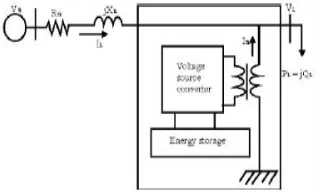
A D-STATCOM (Distribution Static Compensator), which is schematically depicted in consists of a two-level Voltage Source Converter (VSC), a dc energy storage device, a coupling transformer connected in shunt to the distribution network through a coupling transformer. The VSC converts the dc voltage across the storage device into a set of three-phase ac output voltages. These voltages are in phase and coupled with the ac system through the reactance of the coupling transformer. Suitable adjustment of the phase and magnitude of the D-STATCOM output voltages allows effective control of active and reactive power exchanges between the DSTATCOM and the ac system. Such configuration allows the device to absorb or generate controllable active and reactive power.
Fig 2.1: Schematic Diagram of a D-STATCOM
of Zth or fault level of the load bus. When the shunt injected current Ish is kept in quadrature with V L, the desired voltage correction can be achieved without injecting any active power into the system. On the other hand, when the value of Ish is minimized, the same voltage correction can be achieved with minimum apparent power injection into the system.
B.Control Reactive Power for Compensation
Fig2.2: Block diagram of SRF method
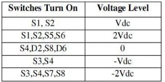
Fig 2.2 shows the block diagram SRF method. Under balanced and sinusoidal voltage conditions angle fI is a uniformly increasing function of time. This transformation angle is sensitive to voltage harmonics and un balance; therefore d fI /d t may not be constant over a mains period. The circuit model of a single CHB inverter configuration. By using single H-Bridge we can get 3 voltage levels. The number of output voltage levels of CHB is given by 2n+l and voltage step of each level is given by Vdc/2n, where n is number of H-Bridges connected in cascaded. The switching table is given in Table 2.1.
Table 2.1Switching table for 5-level CHBInverter
Then for different time values, the voltage values are taken from the harmonics waveform and compared with the reference waveform.
Vol. 5, Issue 11, November 2016
After calculating the voltage error values, next step is to generate training dataset for training fuzzy system. Generating training dataset is one of the most important Processes because based on the training dataset only the Fuzzy control system will be trained. Where Vrefis the voltage value of the system without Harmonics. By using the above dataset, fuzzy system is trained. The fuzzy operation is explained briefly in the below Sections. After completion of training, fuzzy is used for Practical application. After completion of training fuzzy System the next step is to eliminate the harmonic contents in the system. First voltage error values are calculated using the equation 3. By giving voltage error values as input to the Fuzzy system, it gives corresponding frequency and switching angles as output. By applying this frequency and Switching angle values to the system the harmonic contents present in the system are eliminated. The frequency and switching angle are substituted in the equation given below
A.CONSTRUCTION OF FUZZY CONTROLLER
The internal structure of the control circuit. The control scheme consists of Fuzzy controller, limiter, and three phase sine wave generator for reference current generation and generation of switching signals. The peak value of reference currents is estimated by regulating the DC link voltage. The actual capacitor voltage is compared with a set reference value. The error signal is then processed through a Fuzzy controller, which contributes to zero steady error in tracking the reference current signal.
A fuzzy controller converts a linguistic control strategy into an automatic control strategy, and fuzzy rules are constructed either by expert experience or with a knowledge database. Firstly, the input Error ‘E’ and the change in
Error ‘ΔE’ have been placed with the angular velocity to be used as the input variables of the fuzzy logic controller.
Then the output variable of the fuzzy logic controller is presented by the control Current Imax
Fig 2.4: Conventional fuzzy controller
To convert these numerical variables into linguistic variables, the following seven fuzzy levels or sets are chosen: NB (negative big), NM (negative medium), NS (negative small), ZE (zero), PS (positive small), PM (positive medium), and PB (positive big), as can be seen in Fig.3.14.
Fig 2.5 :Membership functions for Input, Change in input, Output.
III. MATLAB/SIMULINK POWER CIRCUIT MODEL OF D-STATCOM
Fig 3.1 Matlab/Simulink power circuit model for D-STATCOM
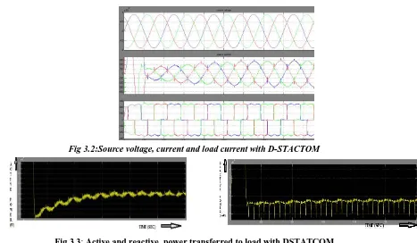
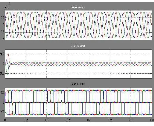
The three phase source voltages, three phase source currents and load currents respectively with DSTATCOM. It is clear that with DSTATCOM even though load current is non sinusoidal source currents are sinusoidal. Three phase source current that is given to by the supply, it consists harmonic content in its wave form as shown in fig.3.3. The active power can be improved with compensation of reactive power using DSTATCOM. Numerically average Real Power 4.5*10^6 Watts
Fig 3.2:Source voltage, current and load current with D-STACTOM
Fig 3.3: Active and reactive power transferred to load with DSTATCOM
Reactive power transferred to load with DSTATCOM
Vol. 5, Issue 11, November 2016
Harmonic spectrum of phase-a source current with and without DSTATCOM
Hence the Total Harmonic Distortion (THD) of source current without DSTATCOM is 29.93% reduced to 6.19% with DSTATCOM.
Fig.3.4: Harmonic spectrum of phase-a source current with DSTATCOM
DSTATCOM WITH FUZZY LOOP CONTROLLER
The Source Voltage, Source Current, and Load Current, of Proposed Cascaded Multilevel Inverter Based DSTATCOM under Inductive load condition with Fuzzy Logic Controller.
Comparison between the level shifted PWM scheme without, with D-STATCOM with Fuzzy Controller
compariso Without D- D-statcom D-statcom
( pi (fuzzy
ns statcom
controller) controller) THD of
Source 29.93% 6.19% 5.04%
Current
VI.CONCLUSION
A D-STATCOM with five levels CHB inverter is investigated. Mathematical model for single H-Bridge inverter is developed which can be extended to multi level H-Bridge. The source voltage, load voltage, source current, load current, power factor simulation results under non-linear loads are investigated for LSCPWM and are tabulated. Finally with the help of Matlab/Simulink based model simulation we conclude that D STATCOM fuzzy controller is better than the pi controller techniques and the results are presented Fuzzy loop controller based D-STATCOM in power distribution system
REFERENCES
[1] K.A Corzine, and Y.L Familiant, “A New Cascaded Multi-level H-Bridge Drive,”IEEE Trans. Power.Electron., vol.17, no.1, pp.125-131. Jan 2002.
[2]J.S.Lai. and F.Z.Pen g "Multilevel converters - A new bread of converters, "IEEETrans. Ind.Appli .• vo1.32. no.3. pp.S09-S17. May/ Jun. 1996. [3] G.Sundar, S. Rama Reddy, “Digital simulation of Multilevel inverter Based STATCOM” published in International Journal of Theoretical and Applied Information Technology, Vol.12, No.12, Feb.2010, pp.19-24
[4]J.Rodriguez. Jih-sheng Lai, and F Zheng peng, "Multilevel Inverters; A Survey ofTopologies, Controls, and Applications," IEEE Trans. Ind. Electron., vol.49 , n04., pp.724-738. Aug.2002.
[5]Roozbeh Naderi, and Abdolreza rahmati, "Phase-shifted carrier PWM technique forGeneral cascaded inverters," IEEE Trans. Power.Electron., vo1.23, no.3, pp. I 257-I 269. May.2008.
[6] [9] G. Sundar, M. Thirunavukkarasu and C. Dhinesh Kumar, “ Ideal Site of Shunt FACTS Devices for Power Flow Control in Long Transmission Line” published in the Research Journal of Applied Sciences, Engineering and Technology,Vol.9,No.10,2015, pp.850-855.
[7]Mauricio Angulo, Pablo Lezana, Samir Kouro, Jos'e Rodr'lguez and Bin Wu, "Level- Shifted PWM for Cascaded Multilevel Inverters with Even Power Distribution" IEEE Power Electronics specialist conference, 17-21 june 2007, pp.2373-2378.
[8]B. P. McGrath and D. G. Holmes, "Multicarrier PWM strategies for multilevel inverters," IEEE Trans. Ind. Electron., vol. 49, no. 4, pp. 858- 867, August 2002..
[9]K.A Corzine, and Y.L Familiant, “A New Cascaded Multi-level H-Bridge Drive,” IEEE Trans. Power.Electron., vol.17, no.1, pp.125-131. Jan 2002.