© 2015, IRJET.NET- All Rights Reserved Page 1858
SYNCHRONIZATION USING PLC
Bini M.Daniel
11
PG Scholar, Energy Systems, Nehru College of Engineering and Research Centre, Kerala, India
---***---Abstract
-.the captive power plant is designedto generate enough power to take the entire load of plant. It is important to ensure the power supply continuously for the efficient working of a plant. Fluctuation in load may lead to the periodical process of the plant. Synchronization of the DG with the bus bar is the only solution for this. Manual synchronization will take more time to take load, which leads to energy loss. Various circuit breaker statuses have to be monitored before synchronization. In order to reduce energy loss during synchronization process, the plant needs an alternative method. My objective is to ensure the synchronization between bus bar and EB, bus bar and DG with smooth process at a leading industry. These conditions are monitored by a PLC. It is the efficient way because of its reliability, effective trouble shooting and can be programmed easily. My objective includes the programming sequence for this PLC unit for the varying parameters and ladder diagrams for various synchronous conditions. Logical continuity is essential for PLC, like electrical continuity for relay logic.
Key Words:
synchronization,PLC etc
1. INTRODUCTION
A leading company in Kerala is my project venue. The electrical system in this industry contains two KSEB incomers and two generators. The incomer is 66KV line and generator ratings are 5MW each. It consists of two main transformers, two unit ratio transformers, six potential transformers and nine circuit breakers. Synchronization is done between the incomers and generators. This is the overall study of my work. Synchronization is timekeeping which requires the coordination of events to operate a system in
unison.
Systems operating with all their parts in synchrony are said to be synchronous or in sync.1.1 Needs for Synchronization
When the DG is running parallel with the grid it is possible to run DG set in base load generation mode. When
there is no KSEB supply we have to meet the total load of the company i.e.8MW, since there are two generators by making them run on the synchronized condition to meet the total load requirement of the company. The active power (MW) and the reactive power (MVAR) can be controlled independently by automatic load sharing circuit by setting MW level and MVAR level to be controlled.
In case if one of the DG set fails to start in the automatic mode, it can be started manually after putting the selector switch in manual position. In this mode the DG incoming breaker has to be manually closed after ensuring that transformer incomer has tripped. The load can be shared in the synchronized condition between the KSEB and DG set by making the voltage and frequency equal in the synchronized condition.
1.2 Synchronoscope
In AC electrical power systems, a synchronoscope is a device that indicates the degree to which two systems are synchronized each other. For two electrical systems to be considered as synchronized, both systems must be together. Connecting two synchronized AC power systems together is likely to severely damage any equipment not protected by fuses or circuit breakers.
1.3 Automatic Synchronization
© 2015, IRJET.NET- All Rights Reserved Page 1859 contactors for contacts to the three phase supply and load,
two contactors separated by their relays and activation and deactivation of every coil of the relay depends on the PLC signal, hence constant magnitude and frequency is obtained in the output. When all the requirements of synchronization is satisfied, closing of the main switch of the incoming machine is done by the automatic synchronizer
1.4 Basic Conditions for Synchronization
Basic conditions to be satisfied before synchronization of generator to bus bar are:
Terminal voltage of the alternator should be approximately same as the bus bar voltage. The difference should be less than 5%.
Incoming frequency and bus bar frequency should be the same. Maximum difference should be less
A Programmable Logic Controller is a digital computer used for automation of electromechanical processes, such as control of machinery on factory assembly lines, amusement rides, or light fixtures. PLCs are used in many industries and machines. Unlike general purpose computers, the PLC is designed for multiple input and output arrangements, extended temperature ranges, immunity to electrical noise, and resistance to vibration and impact. Programs to control machine operation are typically stored in battery-backed-up or non volatile memory. A PLC is an example of hard real time system since output results must be in response to input conditions within a bounded time, otherwise unintended operation will result.
2.1 Introduction to PLC Programming
Early PLCs, up to the mid 1980s, were programmed using proprietary programming panels or special purpose programming terminals, which often had dedicated function keys representing the various logical elements of PLC programs. Programs were stored on cassette tape cartridges. Facilities for printing and documentation were very minimal due to lack of memory capacity. The very oldest PLCs used non-volatile magnetic core memory.
More recently, PLCs are programmed using application software on personal computers. The computer is connected to the PLC through Ethernet, RS-232, RS-485 or
RS-422 cabling. The programming software allows entry and editing of the ladder-style logic. Generally the software provides functions for debugging and troubleshooting the PLC software, for example, by highlighting portions of the logic to show current status during operation or via simulation. The software will upload and download the PLC program, for backup, and restoration purposes. In some models of programmable controller, the program is transferred from a personal computer to the PLC through a programming board which writes the program into a removable chip such as an EEPROM or EPROM. Ladder diagrams are the programming language of the PLC.
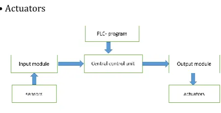
2.2 Components of PLC
A schematic diagram of a programmable logic controller is presented. The basic components of the PLC are the following
• Sensing section
• Input module
• The controller or CPU
© 2015, IRJET.NET- All Rights Reserved Page 1860 output field devices ON or OFF. It provides a control link
between the CPU and field hardware devices. Actuators convert an electrical signal from the PLC into a physical condition. Actuators are connected to the PLC output.
2.3 Sequence of Trials for Synchronization
• Start DG set No:1
• Set 50Hz frequency & 6.6KV voltage • Switch on the circuit breaker & load set
• Readings of voltage & frequency is noted till 2.5MW is reached
• Circuit breaker will be tripped to throw off the entire load
• Readings of voltage & frequency is noted on no load
• If the values are deviating the procedure is repeated 2 or 3 times
• Same sequence is repeated for DG2
• Now DG will be taken up for synchronizing with KSEB grid supply
• Keeping the alternator excitation mode manual, parameters of DG set will be matched to that of grid supply by observing double scale voltmeter, double scale frequency meter & synchronizing synchroscope
• Then circuit breaker • of DG set will be closed.
2.4 Single Line Diagram Showing
Synchronization Between Captive Power Plant
and Main Receiving Station
2.4.1 Synchronization between incomer 1 and
generator 1 (case 1)
Conditions
CB 52.3 IS CLOSED.
CB 52.8 IS OPEN.
CB 52.9 IS CLOSED.
CB 52.8 SYN SW (ON).
52.8 L/R SW(L).
SYN MODE AUTO/MANUAL SW(A).
NGT IS CLOSED.
MASTER TRIP RESET.
V1=V1, F1=F2.
SYN INTERLOCKS.
SYN COND OK.
SYN PERMITTED.
© 2015, IRJET.NET- All Rights Reserved Page 1861
Conditions
CB 52.3 is closed.
CB 52.11 is closed.
CB 52.10 is open.
CB 52.7 SW (ON).
CB 52.10 SYN SW (ON).
52.10 MODE AUTO/MANUAL (A).
NGT CLOSED.
MASTER TRIP RESET.
V1=V2, F1=F2.
SYN INTERLOCKS.
SYN COND OK.
SYN PERMITTED
2.4.3 Synchronization between incomer 2 and
generator 1 (case 3)
Conditions
CB 52.9 is closed.
CB 52.6 is closed.
CB 52.8 IS closed.
C B 52.7 SW (ON).
CB 52.8 SYN SW (ON).
52.8 L/R SW(L).
SYN MODE AUTO/MANUAL SW(A).
NGT CLOSED.
MASTER TRIP RESET.
10.V1=V2 , F1=F2.
11.SYN INTERLOCKS.
12. SYN COND OK.
13.SYN PERMITTED.
2.4.4 Synchronization between incomer 2 and
generator 2 (case 4)
Conditions
CB 52.6 IS CLOSED.
CB 52.10 IS OPEN.
CB 52.11 IS CLOSED.
CB 52.10 SYN SW (ON).
52.10 L/R SW (L).
SYN MODE AUTO/MANUAL SW(A).
NGT CLOSED.
MASTER TRIP RESET.
V1=V2 ,F1=F2.
10.SYN INTERLOCCKS.
11.SYN COND OK.
12.SYN PERMITTED
2.4.5 Synchronization between generator 1 and
generator 2 (case 5)
Conditions
C B 52.8 is open.
CB 52.9 is closed.
CB 52.10 is closed.
CB 52.11 is closed.
CB 52.7 SW(ON).
CB 52.8 SYN SW (ON).
52.8 L/R SW(L).
SYN MODE AUTO/MANUAL SW(A).
NGT CLOSED.
10. MASTER TRIP RESET.
11. V1=V2, F1=F2.
12. SYN INTERLOCKS.
13. SYN CONDITON OK.
© 2015, IRJET.NET- All Rights Reserved Page 1862
REFERENCES
[1
]Ankush.N.Bahale, “Synchronisation of Generators”, Electrical India, Vol 54, No 2, Feb 2014, pp 60-64
[2]Jignesh C Sailor, Prof.S.U.Kulkarni, “Case Study of Industrial Power System for grid synchronisation of captive
power plant”, The Instuition of Engineers (India), Pune, Vol
92, July 2011.
[3]Frede Blaabjerg, Marco Liserre and Adrian V Timbus,
“Overview of Control and Grid Synchronisation for
Distributed Power Generation System”, IEEE Transaction on