© 2017, IRJET | Impact Factor value: 5.181 | ISO 9001:2008 Certified Journal | Page 259
A STUDY & ANALYSIS OF THERMOELECTRIC REFRIGERATION SYSTEM
WITH ENVIRONMENT
Ankit Dubey
1, Umanand Kumar Singh
2, Manish Rathore
3123
Dr. APJ Abdul Kalam UIT, Jhabua
---***---Abstract -
There are various sources which cause ozonedepletion out which conventional R&AC systems has a major role. R&AC contributes for about 29.6% of the total ozone depletion[1]. Ozone in the stratosphere has a beneficial role as
it blocks UV radiation from the sun. Highly energetic UV radiation called UV-C (wavelength 280 nm) is absorbed by the ozone molecules. UV-B radiation (wavelength 280 – 325 nm) is also absorbed. The ozone layer acts as a shield for us from very harmful UV rays. Exposure to UV rays causes skin cancer, damages crops, affects cellular DNA, impairs photosynthesis and harms ocean life. Observed and projected decreases in ozone have generated worldwide concern leading to adoption of the Montreal Protocol that bans the production of CFCs, halons and other ozone-depleting chemicals such as carbon tetrachloride and trichloroethane. R&AC has a vast scope. But the conventional technology using the heat carrying fluids viz. refrigerants (CFCs and HCFCs) renders it unsafe and very harmful. So on the basis of Peltier module Thermoelectric Refrigerator is used for cooling and refrigeration. Thermoelectric cooling [5] technology proves to be a promising
alternative over the conventional R&AC. This technology eliminates the use of refrigerants thereby overcoming the main disadvantage of conventional system i.e. ozone depletion and global warming, Long life than conventional cooling, with mean time between failures (MTBF) exceeding, Able to operate in any orientation , excellent cooling alternative to vapour compression coolers for systems that are sensitive 100,000 hours.
Key Words: Peltier module, Heat Sink, Enclosure.
1.INTRODUCTION
Development of air conditioning and refrigeration is one of the greatest engineering achievements of the 20th century. The efficiencies of both living and non-living beings depend to a great extent on the surrounding physical environment. The nature keeps conditions in the physical environment in a dynamic state, at times changing it from one extreme to the other. The highly efficient and widespread conventional R&AC technology was doing flourishing business producing refrigeration and air conditioning units at its peak. However in 1974, it was discovered that the CFC and HCFC gases, which were the most common refrigerants at that time, deplete the ozone
layer if released into the atmosphere. Thus, the mechanism of ozone layer depletion by the CFC’s and HCFC’s was identified. In 1985, an ozone hole was observed and this provided the proof that ozone layer was depleting.
Contribution of conventional r&ac in ozone depletion
There are various sources which causes ozone depletion out which conventional R&AC systems has a major role. R&AC contributes for about 29.6% of the total ozone depletion. This is a considerably large amount which must be reduced in order to protect the ozone layer CFCs and HCFCs used as heat carrier fluids in conventional system deplete ozone layer and increases global warming. Photo dissociation of halocarbon refrigerants in stratosphere cause ozone layerdepletion. Following chart shows the contribution of R&AC among other sources in harming the Ozone layer.
Fig.1-sources that harm the protective ozone layer
Ozone layer
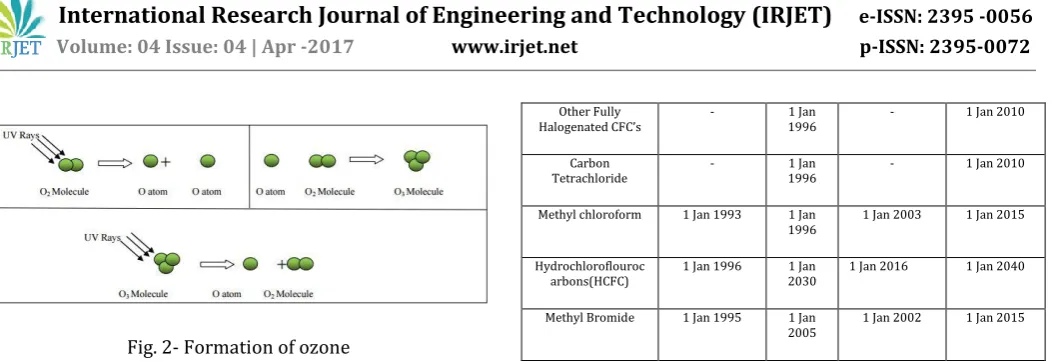
Ozone is present in the atmosphere from the ground up to 50 km altitudes and higher. However, most of the ozone is in a region of the atmosphere called the stratosphere, between 15 and 30 km above the surface of the Earth. This ozone rich region is commonly called the ‘Ozone Layer’.
© 2017, IRJET | Impact Factor value: 5.181 | ISO 9001:2008 Certified Journal | Page 260 Fig. 2- Formation of ozone
CFCs and other heat carriers in Conventional system is the root cause of ozone depletion in stratosphere. CFCs are as freons. Freon 12 is a very common example of Freon. CFC’s are very stable molecules in lower atmosphere, over a period of years they slowly diffuse into the stratosphere. In stratosphere, CFCs are subjected to energetic UV rays.
[image:2.595.38.289.302.390.2]CF2Cl2 + UV Rays CF2Cl + Cl
fig. 3– Decomposition of Ozone
That can cause rupture of carbon-chlorine bond. The chlorine acts as a catalyst for decomposition of ozone. Collision with an ozone molecule results in oxygen transfer forming ClO and molecular oxygen. The ClO formed reacts with atomic oxygen to reform chlorine atom and producing molecular oxygen. The overall reaction is just the decomposition of ozone. Hence CFC’s and other halons are capable of substantially reducing the ozone layer.
Montreal protocol
The Montreal Protocol[6] on Substances that Deplete the Ozone Layer (a protocol to the Vienna Convention for the Protection of the Ozone Layer) is an international treaty designed to protect the ozone layer by phasing out the production of numerous substances that are responsible for ozone depletion. The treaty was opened for signature on September 16th, 1987, and entered into force on January 1st, 1989.
Table -1: control measures of montreal protocol
OZONE DEPLETING
SUBSTANCE DEVELOPED COUNTRIES DEVELOPING COUNTRIES
Consumption
Freeze Phase Out Consumption Freeze Phase Out
CFC 1 July 1989 1
Jan1996
1 July 1999 1 Jan 2010
Halon - 1 Jan
1994
1 Jan 2002 1 Jan 2010
Other Fully
Halogenated CFC’s - 1996 1 Jan - 1 Jan 2010
Carbon Tetrachloride
- 1 Jan
1996
- 1 Jan 2010
Methyl chloroform 1 Jan 1993 1 Jan
1996 1 Jan 2003 1 Jan 2015
Hydrochloroflouroc arbons(HCFC)
1 Jan 1996 1 Jan
2030
1 Jan 2016 1 Jan 2040
Methyl Bromide 1 Jan 1995 1 Jan
2005
1 Jan 2002 1 Jan 2015
Indian Perspective
India signed the Montreal Protocol on September 17, 1992. India’s per capita consumption of ODSs is at present less than 3 grams and did not cross 20 grams in between 1995-97 as against 300 grams permitted under the Protocol. India is self-sufficient in the production of CFCs. India mainly produced and used seven of the 20 substances controlled under the Montreal Protocol. These are 11, 12, CFC-113, Halon-1211, Halon-1301, CTC, Methyl Chloroform andMethyl Bromide.
Table -1: percentage reduction of ods planned in india as per the montreal protocol
R&AC using peltier effect- an alternative technology
R&AC has a vast scope. But the conventional technology using the heat carrying fluids viz. refrigerants (CFCs and HCFCs) renders it unsafe and very harmful. Observing the adverse effects of refrigerants, Montreal Protocol was signed and ozone depleting refrigerants are being phased out. CFC phase out has been achieved by the end of 1996 in developed countries and by the end of 2010 in developing countries. Seeing the harmful effects of CFCs HCFCs were introduced as transitional CFCs replacements. Although HCFCs contribution to global warming and ozone depletion is less compared to CFCs. Still the contribution is quite remarkable. Hence phasing out of HCFCs came into action eventually. Complete phase out is hoped to be achieved by 2030 in developed countries whereas in developing countries it is expected till 2040. Thus we can see that refrigerants are the root cause of all harmful effects caused by R&AC technology.
OZONE DEPLETING SUBSTANCE
2005 2007 2010 2015 2040
Cfc 50% 85% 100% Na Na
Halon 50% - 100% NA NA
Carbon tetrachloride 85% - 100% Na Na
Methyl chloroform 30% - 70% 100% NA
Methyl bromide 20% - - 100% Na
Hydrochloroflourocarbons
© 2017, IRJET | Impact Factor value: 5.181 | ISO 9001:2008 Certified Journal | Page 261 Hence an R&AC technology without the use of refrigerants
has become a necessity in today’s world.
Thermoelectric cooling technology proves to be a
promising alternative over the conventional R&AC. This technology eliminates the use of refrigerants thereby overcoming the main disadvantage of conventional system i.e. ozone depletion and global warming.
Thermoelectric cooling works on the principle of peltier effect. Heat pumping is done by making electrons passing through conductors of different electron densities. The energy absorbed by the electrons travelling from low energy level to high energy level is responsible for cooling.
Long life than conventional cooling, with mean time between failures (MTBF) exceeding
Able to operate in any orientation.
Excellent cooling alternative to vapour compression coolers for systems that are sensitive 100,000 hours.
2. LITERATURE REVIEW
Robert D Heap [1] , has stated that scope of R&AC is vast. It reaches into a huge range of fields we all encounter in our daily lives. At home we use domestic refrigerator. Travelling to work, we use air conditioned vehicles. At work, offices may be air conditioned, computer installations may need cooling, and drink dispensers may be refrigerated. At leisure, pubs, clubs and restaurants need cooling for comfort, for drinks and for safe storage of food. In sickness, we need hospitals with air conditioned operating theatres and refrigerated blood banks, and even at death, refrigeration is to be found as an essential service to mortuaries. Thus R&AC has become an essential ingredient for maintaining and improving our quality of life.
Harmful effects of conventional r&ac
Abel Amare [7], stated that CFC’s and other halons can react with ozone and deplete the ozone layer which could potentially have harmful effects on both plant and animal life on the earth. Decrease in concentration of the ozone layer results in increased amount of UV light reaching the earth due to which the incidence of skin cancers, eye cataracts, interference with photosynthesis in plants, and harmful effects on the growth of plankton will increase. UV-B radiation also affects cellular DNA, impairs photosynthesis, enzymes activity and nitrogen incorporation. This paper shows us that without the presence of ozone layer living things do not have long time to live on the Earth.
K.S. Kavi Kumar [7] , stated that ozone layer in the stratosphere acts as an effective filtering device and blocks the incoming UV-B rays. Increased UV-B radiation is expected to cause adverse health effects – for instance, a 1% increase in stratospheric ozone depletion is estimated to result in a 0.6-0.8% rise in incidence of cataracts; incidence of skin cancer, especially among
light-skinned populations, is likely to increase by 2% for every 1% increase in stratospheric ozone depletion.
R&AC using peltier effect-an alternative cooling technology
Gajendra S. Pache [8], has stated that TE R&AC technology will overcome all the disadvantages of existing R&AC system. Conventional R&AC system has many disadvantages like use of -hazardous refrigerants, bulky system, orientation problems, etc. The new R&AC system using thermoelectric couple which shall overcome all the disadvantages of existing R&AC system which gives advantages like environment friendly, precise temperature control, spot cooling, compact, high reliability, electrically quiet operation, ability to heat and cool with the same module.
S.B. Riffat, December 2002[3], has stated that TE R&AC systems are environment friendly as CFC gas or any other refrigerant gas is not used, due to which they have many potential applications. The most widely used thermoelectric material in the temperature range of 120 to 230 0C is a pseudo-binary alloy, (Bi,Sb)2(Te,Se)2,
commonly referred to as bismuth telluride. For normal thermoelectric devices maximum temperature difference between the hot and cold side can reach 70
0C. Large temperature differentials (up to 130 0C) can be
achieved by multistage (cascade) series. The lowest practically achievable temperature is about -100 0C. This
system has no moving parts and therefore, need substantially less maintenance, life of these devices exceed 100,000 hrs of steady state operation, it can function in environments that are too severe, too sensitive, or too small for conventional R&AC system.
THERMOELECTRIC REFRIGERATION
Manoj Kumar Rawat, Feb 2013 [5], has designed and developed an experimental thermoelectric refrigeration system having a refrigeration space of 1 litre. Cooling is achieved by using four thermoelectric cooling modules (Qmax=19W) and a heat sink fan assembly (Rth=0.50
0C/W) for each thermoelectric module which is used to
increase heat dissipation rate. A temperature reduction of 11 0C without any heat load and 9 0C with 100 ml of
water in refrigeration space with respect to 23 0C
ambient temperature has been experimentally found in first 30 minutes at optimized operating conditions. The calculated COP of thermoelectric refrigeration cabinet was 0.1.
Gao Min, 2006, has developed a number of prototype thermoelectric refrigerators with different heat exchanger combination and evaluated their cooling performances in terms of COP, heat pumping capacity, cooling down rate andtemperature stability. The COP of refrigerator is found to be 0.3-0.5 for typical operation temperature of 5 0C with ambient at 25 0C. The potential
© 2017, IRJET | Impact Factor value: 5.181 | ISO 9001:2008 Certified Journal | Page 262 employing a realistic model with experimental data
obtained from this work. The results show that an increase in its COP is possible through improvements in module contact resistance, thermal interfaces and effectiveness of heat exchangers.
Thermoelectric refrigeration using solar energy Dai Y.J. Wang, 2003, has designed and developed a
thermoelectric refrigeration system powered by solar cells. The prototype consists of a thermoelectric module, array of solar cells, controller, storage battery and rectifier. The system with solar cells and thermoelectric refrigerator is used for outside purpose in daytime and system with storage battery, AC rectifier and TER is used in night time when AC power is available. Experimental analysis on the unit was conducted mainly under sunshine conditions. The studied refrigerator can maintain the temperature in refrigerated space at 5-10
0C and has a COP of about 0.3 under given conditions. Sabah A. Abdul-wahab, 2009, has designed and
developed an affordable thermoelectric refrigerator powered by solar cells for the desert people living in Oman where electricity is not available. The design uses 10 thermoelectric modules. The finned surface (heat sink) was used to enhance and increase the rate of heat transfer from the hot surface of thermoelectric module.
Developments in TE technology
Robert A. Taylor, December 2005 [2], stated that to fully realize the benefits of TE R&AC, system level optimization is essential. Critical optimization of TE geometry, electric current & material performance can improve TE R&AC technology. TE geometry optimization process suggests that a thinner TE element is needed. It is found that even if electric current and geometry are optimized, performance benefit will be very small at high heat loads. While improving material performance it is found that for bismuth telluride, if the effective thermal conductivity were to be reduced by 10%, it would cause an 11.1% increase in figure of merit. Whereas if the effective thermal conductivity were reduced by 25%, it would cause a 33% increase in figure of merit. 13
John C. Bass [4], has stated that Thermoelectric modules in use today have a COP of only about 0.5. This compares to COPs of larger scale machines, such as air conditioners and refrigerators at levels of 3.0 to 5.0. For electronic component cooling there is a new class of thermoelectric materials that has resulted from recent R&D. These are categorized as “low-dimensional” thermoelectrics and they have the potential to increase COP greatly. These are super-lattice thin-films, also called “quantum wells”. This type of structure provides higher value of figure of merit, ZT. This paper discusses new technology which is multi-layer quantum well (MLQW) that should increase the COP by four to five
times of the present thermoelectric modules used in electronic cooling applications.
3. METHODOLOGY
The project methodology comprises of the following 5 essential steps:
Selection of Peltier Module
Circuit Design
Microcontroller Programming
PCB Layout
Fabrication of final prototype
Selection of Peltier Module: Here we choose a mid-range Peltier Module of low cooling power for our prototype. So, we select TEC12706, with a cooling capacity of 50-57 watts.
Circuit Design: After the selection of Peltier Module, we now need to decide the components that we need to include in the circuit according to our logic. Peltier Module needs to controlled by a microcontroller which needs 5VDC supply. Hence we need a step down transformer and IC7805 to maintain the 5V voltage supply. Likewise, we’re using temperature sensor LM35, LCD display, resistors, capacitors etc.
PCB Layout: For the design of PCB, we firstly draw schematic of PCB in ExpressSCH program. Using the software ExpressPCB.we construct the PCB layout by inserting required components at proper places. Then the schematic is linked with this saved PCB file. Due to this automatically connections are made and tracks are developed. A print of this is taken on a paper. Then this paper print is placed on the board and the image is transferred on to it. Now the circuit board is ready for further process i.e. drilling, etching and plating. Drilling is done to establish an electrical interconnection between the top, bottom and intermediate conductor pathways. Plating is the mechanical treatment for the drilled holes. The unwanted copper is removed from the board by etching. Finally, the portions that remain on the board carry electric current between the devices.
Fabrication of final prototype: After the design of PCB layout, we finally solder the components at their appropriate positions on the PCB. After this, the enclosure that is to be cooled is fabricated.
Discovery of peltier effect and its use in cooling
© 2017, IRJET | Impact Factor value: 5.181 | ISO 9001:2008 Certified Journal | Page 263 Michael Faraday, a Briton, had discovered the law of
practical electric generation, or electrical induction in 1831. It took over 50 years from this discovery to the commercialization of alternate current electricity generator. It was in 1954 that people had ideas to make thermoelectric refrigerator or air conditioner i.e., about 70 years later from the first commercial alternate current generation. In this year, N.E. Lindenblad, American, made a small refrigerator using lead/telluride (PbTe) and antimony/telluride (SbTe) as the thermoelectric junctions. In the same year, H.J. Goldsmid, at General Electric Company, got a remarkable ΔT of 26°C, never obtained before, using Bi2Te3/Sb2Te3 as the P type and Bi as the N type. In the next year, 1955, his group obtained an outstanding ΔT of 46°C with the thermoelectric junction of P and N type bismuth telluride. The rapid performance enhancement of bismuth telluride made this material a promising choice with far better performance. From this reason, experimental fabrication of refrigerators and air conditioners, targeting at future use of them in offices and homes, were aggressively done.
Analogy with conventional system
[image:5.595.304.562.78.224.2]A thermoelectric refrigeration system is a cold junction, a heat sink, and a DC power source. TE technology is analogous to conventional system in following aspects.
Table 2.- Analogy of te cooling with conventional cooling
Conventional cooling Thermoelectric cooling
Refrigerant in liquid and vapour form. Two dissimilar conductors. In, evaporator energy is absorbed by the
refrigerant as it changes from liquid to vapour.
Cold junction(evaporator surface)
becomes
cold due to absorption of energy by the electrons as they pass from one semiconductor to another In condenser, heat energy of the
refrigerant
is rejected as the refrigerant itself gets condensed
The heat sink (condenser) discharges the accumulated heat energy from the system.
Compressor is used to pump the refrigerant
throughout the refrigeration cycle.
Compressor is replaced by DC power source which pumps the electrons instead of refrigerant.
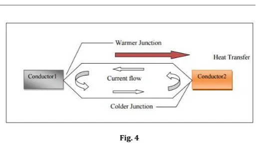
PELTIER COOLER MODULE
Peltier cooler modules are semiconductor based electronic components that can pump heat from one side of the device to the other depending on the direction of current. They are also known as thermoelectric module of thermoelectric coolers.
The device to the right is called a couple. One side is attached to a heat source and the other a heat sink that convects the heat away. The side facing the heat source is considered the cold side and the side facing the heat sink the hot side. Between the heats generating device and the conductor must be an electrical insulator to prevent an electrical short circuit between the module and the heat source. The electrical insulator must also have a high thermal conductivity so that the temperature gradient between the source and the conductor is small. Ceramics like alumina are generally used for this purpose.
Fig. 4
4. APPLICATIONS
Although the Peltier coolers are more expensive than conventional compressor units, there are a multitude of application challenges which can only be solved by using Peltier cooling components. Special emphasis can be given to miniature cooling, for example, which involves only small cooling capacities. But more significance should be given to the fact that Peltier blocks can be controlled electronically, and therefore provide a control precision level that cannot be achieved with compressor cooling. Another advantage of Peltier cooling/heating is that it is easily convertible. Simply by reversing the polarity of the DC voltage, heat can be produced where it was cooling previously, and vice versa. The application possibilities multiply when not only cold, but also heat is to be produced with the smallest possible units, and/or wherever a continuous change between cooling and heating is needed.
Current applications [4]: 1. Coolers/heaters
Usually, Thermoelectric coolers are used in cases where the cooling system design criteria includes such factors as high reliability, small size, low weight, intrinsic safety for hazardous electrical environments, and precise temperature control. Thermoelectric coolers are more appropriate for niche applications (under 25 W) because their low COP is not an apparent disadvantage.
2. Cooling CCDS
Charge-Coupled Devices (CCDs) are electronic devices that transform a light pattern (image) into an electrically charged pattern, creating an electronic image. CCDs are used in applications that are not visible to the naked eye, such as high-speed testing, night vision, medical diagnostics, and quality control inspection systems. A TEM can be integrated into the CCD system to cool the CCD to low temperatures and increase the light spectrum captured by the CCD. Another major concern with CCD equipment is operating in vacuum environments due to the issue of out gassing
5. CONCLUSION
© 2017, IRJET | Impact Factor value: 5.181 | ISO 9001:2008 Certified Journal | Page 264 systems. The study concludes that there are a no. of places
where TEC can play a more promising role than the conventional ACs with the added advantage of not using the refrigerants and hence protecting the ozone layer. With its reliable cooling and precise temperature control, this solid-state cooling technology can replace conventional cooling in a multitude of applications. Also with the advancements in material technology, there shall be a drastic rise in the cooling performance.
This project was just an effort to demonstrate the need and means of replacing the conventional systems due to their adverse environmental effects and to highlight the future scope of the Thermoelectric Cooling Devices.
REFERENCES
[1] Robert D. Heap, “Safety and Hazards in the Refrigeration
Industry”, IIR Science and Technology Counci
[2] Robert A. Taylor, Dec 2005, “Comprehensive
Optimization for Thermoelectric Refrigeration Devices”, University of Missouri – Columbia.
[3] S.B. Riffat, Dec 2002, “Thermoelectrics: a review of
present and potential applications”, University of Nottingham, NG7 2RD, UK.
[4] John C.Bass, “New Technology for Thermoelectric
Cooling”, 20th IEEE SEMI-THERM Symposium
[5] Manoj Kumar Rawat, Feb 2013, “A review on
developments of thermoelectric refrigeration and air conditioning systems: a novel potential green refrigeration and air conditioning technology”, Int. Journal, ISSN 2250-2459, Volume, pages 362-367.
[6] K.S. Kavi Kumar, “Montreal Protocol”, Madras School of
Economics, Chennai.
[7] The University of Maryland McNair Scholars
Undergraduate Research Journal, 2, (2010): 19-25
[8] Gajendra S. Pache, “HVAC (Heat Ventilation and Air