Recent Developments of an Aircraft Fuselage along
Theoretical, Experimental and Numerical
Approach - A Review
Varun Potty1, Sohan Angelo1, P. Srinivasa Rao2, Srinivas G3,*
1
Manipal Institute of Technology, Manipal Academy of Higher Education (MAHE), India
2
Department of Humanities and Management, Manipal Institute of Technology, Manipal Academy of Higher Education (MAHE), India
3
Department of Aeronautical and Automobile Engineering, Manipal Institute of Technology, Manipal Academy of Higher Education (MAHE), India
Received August 29, 2019; Revised December 17, 2019; Accepted December 24, 2019
Copyright©2019 by authors, all rights reserved. Authors agree that this article remains permanently open access under the terms of the Creative Commons Attribution License 4.0 International License
Abstract
Expressed in nature’s infinite subtleties, the Fuselage draws its inspiration from the streamlined body of a bird or a fish, channelizing the flow of air around, enabling its ease in flight. Spanning most of the aircrafts structure, it plays a crucial role in the ferrying of people and cargo, simultaneously balancing the shears due to the empennage and wing structures all in mid-air. Its structural integrity is often questioned by failures due to load or bad air during maneuvers, causing instability which has led many to intensively explore and develop an ideal fuselage. The behaviour of the fuselage is crucially determined by the structural integrity and aerodynamic performance. This paper is an attempt at collating the recent technological advances pertaining to the fuselage. We’ve streamlined and categorised the wide-ranging scholarly articles by three fundamentally varying approaches - Theoretical, Experimental and Numerical. The theoretical approach saw the authors test out their hypothesis by utilizing and constructing various mathematical models using scientific principles with no verification by actual experimentation or simulation work. The experimental approach pertains to those papers whose authors devised experiments, whose data was used to draw distinct conclusions. The numerical approach mainly dealt with heavy computational analysis using FEM and CFD analysis. Therefore, this paper serves as a compendium for researchers and developers attempting to familiarise themselves with the current advancements and developments in domain of fuselage technology.Keywords
Fuselage, Performance, Analysis, Aircraft1. Introduction
The race to develop the most commercially successful and renowned passenger aircraft has shifted gears to focus on research topics closely pertaining to the fuselage. The
fuselage is the most recognizable component of the aircraft and it refers to the long hollow tube which encloses the cargo and passengers along with the crew of the plane. The fuselage forms the center piece around which the aircraft structure is built. The fuselage structure has had to adapt with the changing times and working specifications, resulting in four major types – Truss structure, Geodesic construction, Monocoque shell, and Semi-monocoque fuselage. The more commonly adapted method of construction utilized is the Semi-monocoque fuselage, owing to its ease of reproducibility in the manufacturing process and ease of working with metals. The general structure of the fuselage varies based on application and prerequisites in the working conditions of the aircraft.
Each aircraft is required to adhere to rigorous regulations, reiterating its ability to come out of worst-case scenarios unscathed, which is attributed to the structural integrity of the fuselage. The gains (loss of weight) made by design alterations to the blueprint of the fuselage, by integrating new age composite materials and changing the fundamental structural design, cannot be at the cost of structural integrity of the fuselage, putting the safety of the aircraft in jeopardy. The fuel consumption of the aircraft is inordinately dependent on its aerodynamic performance in flight. Aerodynamics of the aircraft plays a crucial role in efficiently developing lift without exponentially increasing drag. The aerodynamic design is an aspect that is heavily taken into consideration in the initial stages of the design process. The ability of the aircraft to follow the computed trajectory throughout the 3 phases of flight and the relatively low latency in reaching equilibrium after hitting disturbances in the air are in part due to the aerodynamic performance of the aircraft.
opportunity, the bigger players in the field of aeronautics have made a major push towards reducing the cost incurred by the passenger. In tandem with increasingly stringent environmental standards, this has set the future trend for fuselage design to accommodate aircrafts that have a smaller environmental footprint along with increased seating capacity and shorter travel times without compromising on safety. This implies that fuselage will have to withstand forces at supersonic flight, consist of materials made of lighter and yet stronger composite materials and undergo a transformation in the design philosophy. Plans to make the fuselage structures smarter by incorporating health-monitoring and fault-tolerant mechanism and more robust flight control systems are in the works. Attempts to improve aerodynamic efficiency by means of active flow control systems are also being taken into consideration. In an attempt to improve the optimization process of the fuselage design, two main characteristics are taken into consideration –Structure and Aerodynamics.
2. Literature Review
2.1. Theoretical Analysis of Aircraft Fuselage
Yuan Li et al [1] intends on decreasing the errors of displacement between two fixtures of the fuselage as compared to an ideal theoretical model. Errors in displacement of fixtures (error between coordinates along the fixture and its theoretical counterpart) are calculated based on geometric constraints using the Gauss-Newton algorithm. The initial value of the coordinate was obtained. If error above a threshold is present, the coordinates are transformed to new ones by multiplying them with a transform function. After certain iterations if error still persisted, the weightage of each error pertaining to each constraint was changed, and the process was repeated. The algorithm was applied onto coordinates of the fuselage and the errors obtained between the physical and theoretical model were within the required margin. This multi-objective optimization mode which considers constraints performs better than the ones traditionally employed in the field of posture adjustment.
John T. Wang et al [2] identified the need to devise methods which determined the strength of damaged composite fuselage panels, as the preexisting methods did not consider the geometrical nonlinear effects and were tedious to use. The objective of their research was to ascertain the effectiveness of the Resisitance-curve (R-curve) method to predict the residual strength of damaged composite fuselage panels accounting for hoop, axial and pressure loads. The R-curve constructed was used to test the nonlinear behavior and the residual strength of both flat and curved composite cracked plates. All the results were validated with reference to data conducted using two different methods called gradient method and virtual crack closure technique. In the end they concluded that the correlations between the data sets were very similar and that the R-curve method could be used to determine the strength
of damaged panels.
Adrien Boulle et al [3] examined the feasibility of using a pressurized elliptical fuselage over a circular one. Three different elliptical fuselage constructs considered were: monolithic (having no core, only facesheet whose thickness varies with polar angle), symmetric (a core encompassed by 2 facesheets both of equal thickness and varying with polar angle) and asymmetric (a core encompassed by 2 facesheets of unequal thickness and varying with polar angle). Volumes of the facesheets were calculated and used as substitutes for the mass. A series of mathematical formulas were used to calculate the tangential force bending moment, and max stress conditions were used as constraints to derive the thickness of the face sheet. A monolithic structure was proved to be less beneficial, whereas the symmetric structure, though better than the monolithic, was structurally underused. The asymmetric structure was proved to be most beneficial, with only 1% weight gains and a lot more available area.
C.Hesse [4] proposed and built a theoretical model that actively attenuates sounds within an enclosed right cylindrical composite fuselage using a series of actuators and sensors integrated into the structure. The main objective was to construct a general mathematical model which was applicable to a wide range of fuselage designs. This system termed as Active Structural Acoustic Control (ASAC) relies on Acoustic Radiation Modes (ARM) to determine the contributions made by the fuselage to internal sound. The mathematical model for the ARMs was constructed by assuming the fuselage to be the main proponent of the disturbance, disregarding support structures. This model was tested on a Finite Element Model (FEM) of a composite fuselage. The tests determined the number of ARMs necessary to effectively represent the sound field and set the limits to which the system would dampen the sound field. They concluded that this would be representative of the dampening effects despite of irregularities that could possibly be found in fuselage structures.
indicated a significant increase in lift coupled with drag reductions under medium to high lift coefficients, implying a net positive effect. The Reynolds number influence showed unreliable results indicating a better integration of the mini-TEDs into the wing structure was required for efficient functioning. Overall, the results showed great promise for the mini-TEDs in improving the aerodynamic efficiency of future aircrafts to come.
Tung Wan et al [6] analyses the change in performance of an aircraft due to heavy rain. Using a new analytical system, Navier-Stokes equation was applied on every triangle generated by modified Bowyer scheme grid generation. Cratering effect of the water layer is considered along with the terminal velocity of the droplet and the air density. It was found that the lift coefficient of an aircraft in rain was greater than that at normal times when the angle of attack was zero. With the increase in angle of attack, the reverse occurred. The stall angle of attack decreased because of downward force exerted by the droplet. Development of a water film was observed to cause more aerodynamic degradation than the density of water in air or the velocity of the droplet.
Pierluigi Della Vecchia et al [7] introduced a new method to evaluate lift characteristics of a transport aircraft. Nasa Blackwell method, where the horse shoe vortex is applied on straight wing elements, was modified. This predicted wing stall characteristics of the flaps in active and retracted condition. A method to compute effect of high lift devices was also established. A maximum lift curve was also computed. The values of lift coefficient obtained for a clean configuration using the new system when collated with those from CFD analysis show discrepancy of less than 5%. The new system is thereby validated.
Trailing vortices created in the wake of an aircraft have detrimental effects hypothetically leading to catastrophic consequences in extreme conditions on oncoming aircrafts. Aziz Al-Mahadin et al [8] aims to determine crucial factors and parameters contributing to incidents caused by these trailing vortices. They go about bringing these correlations by weeding through pilot reports of flight incidents (54 pilot reports in this study) and establish factors that influence vortex interactions. They narrow the possible culprits down to 9 factors – Aircraft model, flight phase, Altitude at which the incident occurred, aircraft mode, response parameters, wind speed and direction, visibility, separation and roll angle vs altitude. The authors recommended that a more standardized reporting structure be established, which worked in tandem with on-flight data and pilot accounts so as to remove subjectivity in case reporting.
Figure 1. Trailing Vortices in the wake of the Airplane [8]
Fabrizio Nicolosi et al [9] strived towards predicting and quantifying the aerodynamics related coefficients acting on the fuselage. New methods for the assertion of drag, yawing moment and pitching moment were established. A turboprop fuselage having 3 segments (nose, cabin, tail) of length 30m and diameter 3.4m was considered as reference, based on which 5 other models were generated by varying one of the three segments. Meshing of the model and creation of atmospheric conditions were done using STAR CAM+ software. Drag coefficients acting were predicted by summing up the individual coefficients obtained at the nose, body and the tail. Pitching moment coefficient and yawning moment coefficients were calculated considering the geometry of each given model. Results obtained using the new paradigm were in correspondence with the ones generated using CFD model. The proposed model highlights the significance of the geometry of the structure in question. Huang Jiangtao et al [10] propounded the use of neural networks for the aerodynamic optimization of a supercritical wing, hence reducing the drag coefficient. An improvised Back Propagating Neural Network algorithm was developed considering the Mach number. The neural network using an unconventional learning approach generated a testing model akin to a CFD model. The error detected between the CFD and the neural network was minimal. The optimized aircraft wing in contrast with the original one resulted in weaker shock waves. The drag coefficient had also considerably reduced.
3. Experimental Analysis of Aircraft
Fuselage
NASA in collaboration with Boeing designed, fabricated and tested a Pultruded Rod Stitched Efficient Unitized Structure (PRSEUS a new age fuselage) fuselage panel and demonstrated its ability to withstand damage in line with regulations, demonstrating relative advantages over its contemporaries. Further building on this work, Andrew Bergan et al [11] attempted to test the damage progression in a curved panel of the same kind under various types of loads and stresses. The testing process was broken down to 3 stages, first, a baseline test with loads in compliance to 14 CFR 25.305 (FCC Regulation). Second, the Barely Visible Impact Damage (BVID) panel was exposed to loads to check the ultimate strength in requirement with 14 CFR 25.305 (FCC Regulation). Third, the panel was loaded, and the axial loads were increased while the failure process was monitored until catastrophic breakage point was reached. After a thorough inspection and analysis, it was concluded that panel followed all the regulations and their experiment provided reference and validation for a theoretically predicted failure and load bearing capability.
[image:3.595.93.262.665.770.2]to improve and expand the detection area, rate and accuracy of monitoring system by implementing a sensor network of serial-connected PZT connected in conjunction with an Ultrasonic Propagation Imaging (UPI) system. The PZT sensors were appropriately placed to cover the optimum amount of fuselage skin and at a suitable distance from the stringer. Cracks of varying depth were made in areas where they would naturally occur. The system could create both 3-D and 2-D maps of the fuselage skin and could provide detailed location and information of all the cracks to a certain degree of error, when the UPI and the Milti-timeframe Ultrasonic Energy Mining (mUEM) system worked in tandem. The authors concluded that structural health management (SHM) system was a cheap and viable solution to detect faults in the structure of the fuselage, acting as a maintenance system.
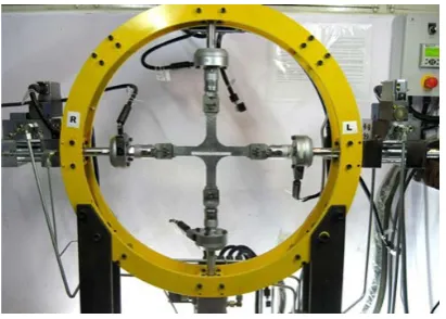
R. Sunder et al [13] identified the general lack of consensus in analytical studies on fatigue crack growth when exposed to biaxial loading caused by cabin pressure in the fuselage. This inability or lack thereof reproducible and digitally controlled system to test this phenomenon persuaded them to construct a standardized experimental setup and investigate for the circumferential crack progression in fuselages of aircrafts. The experimental setup devised by the authors is given in figure 2. The main goal was to practically validate the theoretically predicted stress intensity range under biaxial forces and the FEM based model, hence confirming its ability to estimate crack sizes. Second, using Marker-TWIST, a modified version of TWIST load spectrum generated qualitative fractography. After conducting the tests on steel and AL-alloy, the results were analysed, and they concluded that the crack growth was intrinsically connected to the biaxial load and spectrum loading.
Figure 2. Experimental load frame setup for the application of biaxial
forces on a fuselage cross section. [13]
Ren Yiru et al [14] analysed the crashworthiness of the fuselage that had been modified to accommodate a sine wave beam instead of the traditional fuselage bottom. The modified fuselage and the conventional one were dropped from a height. The energy dissipation along with acceleration and velocity of the fuselage and its displacement (compression) was noted. The sine wave beamed fuselage reduced the initial peak load and also increased energy absorption of the structure and unlike the conventional
fuselage, the cargo floor didn’t collide with the cabin floor, thereby avoiding a peak in acceleration at that point. The deformation of the strut decreased with an increase in its rigidity. The sine wave beam was a more effective solution than the conventional one.
Roy GEBBINK et al [15] in collaboration with the Chinese Aeronautical Establishment (CAE) devised a wind tunnel experiment to monitor the aerodynamic stability and performance in the cruising stage for different configurations of the aircraft. In tandem with this, they intended to develop a dataset for the validation of computational fluid dynamics algorithms. The setup consisted of 3 major steps, and the primary setup consisted of aerodynamics validation model (AVM) being mounted upside up on the Z-string instrument. This was followed by the AVM being mounted upside down on the dorsal blade sting. Finally, the AVM was mounted on the dorsal blade sting with a dummy Z-support installed. After an inspection of the results, the authors concluded that they had successfully established a dataset for two aircraft configurations across a wide variety of loads and flow conditions between Mach numbers of 0.4 to 0.9. They also determined that the repeatability and replication of the experimental setup and its results fell within acceptable error margins, and hence be used as the basis for future validation of experiments.
Most run of the mill commercial aircrafts with a vertical tail displayed high levels of instability at medium to high angles of attack. J. Wen et al [16] construct and put an aircraft to the test to encapsulate the specific structures of the aircraft contributing to the yawing moment. In order to individually test parts and check its effect on the whole aircraft, they decide to have all the parts be detachable. They investigated this characteristic using particle image velocimetry (PIV) in tandem with a pressure test. The results indicated that vertical tail and the fuselage were mainly responsible for the yawing motion of the basic aircraft. They concluded that flow field in major regions of the fuselage were adversely affected by increase in the angle of attack which was heavily responsible for the instability.
ZurriatiMohd Ali et al [17] developed an experiment to investigate the impact of canard angle on the aerodynamics of a blended wing body aircraft. The visualization of the air flow was enabled by using a physical mini bust model of a BWB aircraft when set at different angles of attack. A one sixth scale model with a rectangular canard was manufactured from aluminum. The tests were run at a velocity of 35m/s. The results of the tests indicated a drastic drop off in the lift to drag ratio when the angle of canard hit 15 degrees. They concluded that aerodynamic stability was drastically impacted by an increasing canard angle.
[image:4.595.76.282.497.644.2](DC), Direct Allocation (DA) and Fixed-point iteration (FXP)) to reduce the trim drag. The trim drag was the highest with the use of DC algorithm and lowest with the use of DA. The introduced paradigm to reduce trim drag can be used for BWBs of various structures and designs.
4. Numerical Analysis of Aircraft
Fuselage
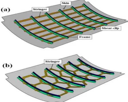
Maher Bouazizi et al [19] devised an experiment to inspect the performance of hexagonal reinforced grid configuration, definitively determining the relative merits with respect to the standard orthogonal reinforced grid layout characterized by designated parameters. The objectives were, first, to investigate the changes in the functioning of fuselage with changes in design of the orientation. Second, to observe the changes when the frames were replaced with material used to strengthen the pre-existing hexagonal grid structure. The standard experiment was simulated, where the three structures were exposed to cabin pressures in varying degrees. The results were examined on basis of Eigen frequencies, stress experienced by the fuselage and displacement in the structure of the fuselage by keeping length of each stringer the same and the configuration in terms of number of grids in the axial and longitudinal direction the same. The design of the fuselage panels is given in Fig 3. The results showed that the Hexagonal Grid Stiffened Panel (HGSP) with frames fared the same with respect to Orthogonal Grid Stiffened Panels (OGSP) but was considerably lighter. But the strengthened HGSP without frames showed higher Eigen frequencies and lower radial displacement responses with increased stresses in the in-plane shear stress in the skin. This clearly indicates that there is an optimum condition to be reached in terms of frames with hexagonal grid pattern.
Figure 3. (a) Orthogonal Grid Stiffened Panel with Frames (b) Hexagonal
Grid Stiffened Panel withFrames. [19]
P.Linde et al [20] recognized the increasing role stiffened fuselage panels with laminated construction played on the aircraft and found the need to test the post bucking behaviour of these panels under load. ANSYS and LS-DYNA were the
software packages used for modelling and testing the finite element. Delamination and boundary conditions were explicitly considered during modelling. Mathematical computation of the panel through and after the buckling was discussed and a connection was established between them. It was also noticed that the modelling of the boundary condition influenced the structure. Though no sample set of data was explicitly presented, the research claimed that the numerical model was in accordance with the experimental results.
D.Perfetto et al [21] aimed at validating a new numerical model of a fuselage drop test by comparing it with experimental results. A physical and numerical drop test of fuselages containing dummies was conducted and then compared. The components of the fuselage were first accurately modeled. Then the simulated aircraft was made to land with a pitch of 2.28 degrees, replicating the fall of the actual physical model. The deviations between the mathematical and experimental deformations were within the range of 90mm. The numerical model was not as rigorously drafted as it should have been, therefore, it was prone to errors. Nonetheless it was an accurate system.
F.Marulo et al [22] recognized the growing versatility of new age composite materials and intended to configure ways to integrate them into the aircraft fuselage, which is in line with regulations. The main objective of their research was to envisage new designs for the lower lobe of the aircraft fuselage primarily comprising of materials. They also intended to codify concrete procedures to test and incorporate these materials into future designs whose features aids in its response to crashes or “crashworthiness”. Qualities like energy absorption and crash response were put to the test with a combination of simulators like LS-DYNA and FEM models, recreating the test on a real fuselage. These tests were first performed on the barrel section of the fuselage and then specifically to the detailed lower lobe of the fuselage, giving attention to how each individual part performed in the event of a crash. They concluded from the results that pre-existing structures mainly stanchions in current day airplanes, need to be redesigned to enhance the effectiveness of composite materials in fuselage designs.
MOU Haolei et al [23] inspects the crashworthiness of fuselage section made up of composite skins. Drop test for each of the structure was simulated on the LS-DYNA software with an impact velocity of 6.67m/s. Three rows of seats with concentrated masses on them were modeled (using Hyper Mesh), but only the central row was considered. The acceleration response and failure mode of the fuselage were noted for structures with skins of different ply number and ply angle. An increase in ply number increased fuselage stability, but also caused a rise in stress and led to earlier peak acceleration. With certain values of ply angles the energy absorption by the fuselage structure became more efficient, also decreasing stress values. The aforementioned results validated certain composites, thereby affirming the fact that ply number and ply angle play an important role in improving the crashworthiness of a structure.
[image:5.595.65.289.523.700.2]in a composite fuselage formed during the manufacturing process, can be fixed using a set of actuators without critically damaging its structural integrity. A FEM of a composite fuselage with appropriate parameters along with fuselage geometry, fixture structure and actuators design and positioning was constructed. This model is further refined based on data collected from results of the same setup executed in real life so as to accurately mimic the fabrication process. This is followed by failure test, stress/strain analysis and a dimensional control analysis. The results showed that the actuators were capable of modifying the fuselage to the ideal shape with less than 1000 pounds of force without causing damage to the composite fuselage. In general, they concluded that their procedure could be used to make corrections to deformed fuselage and requires more research to make the process more efficient.
Ju et al [25] analyzed the dynamic Stress Intensity Factor (SIF) of a longitudinal crack in the fuselage when subjected to various types of loadings. The FEM generated was subjected to both triangular and trapezoidal loads (dynamic loads) along with various static loads for various crack sizes with varied time intervals of application and there after their respective graphs were compared. The peak SIF value obtained under dynamic loading was greater than that seen under static loading and this variation increased with increase in crack size. The dynamic SIF curve and the dynamic load curve applied, share similar shapes. The dynamic SIF curve sees considerable changes when the loading time varies. The stimulated data obtained was in accordance with the theoretically predicted observations.
Venkatesha B K et al [26] probes the rate of growth of a longitudinal crack due to fatigue. The frames ability to arrest the growth of a longitudinal crack was tested. MSC NASTRAN was used for stress analysis of the modeled panel. The load and the boundary conditions were applied such that the tensile load due to internal pressurisation was uniformly distributed through the cross-section. A crack was initiated at a rivet hole which happens to be the location of the maximum tensile stress. Modified Virtual Crack Closure Integral (MVCCI) determined the SIF and the damage growth rate under constant fatigue loading were obtained. SIF increased with increase in crack length, but its value decreased on nearing a frame. Fatigue crack growth rate increased with loading cycles and as these cycles increased, the growth rate shot up till it reduced when the crack reached the frame.
Chuin-Shan Chen [27] aims to predict the residual strength of a fuselage under the crack tip opening angle criterion. A study on ductile tearing simulation was also presented, with an analysis on thin shell finite element. A fuselage panel with a saw cut, was subjected to pressure until a crack stretching across two frame bays was developed. A finite element model of the panel was generated to assess the crack growth. The Crack-Tip Opening Angle (CTOA) from flat panel tests was calibrated and then the theoretical data was compared with the experimental one. Results showed that a panel with multiple site damages had a residual strength reduced by 28 to 47%. The residual strength also changed with change in CTOA. A broken tear strap caused further reduction in strength by 24 to 30%.
Mario Jaime Martin-Burgos et al [28] recognizes the inadequacies in present day simulation softwares to adapt the computational grid upon encountering deformation or irregularities in the surface being computed for, requiring them to reconstruct the mesh at every step. These shortcomings in the simulations normally cluster around interstices of components with varying topologies like fuselage-wings or intersections of moving parts. The authors hence construct an algorithm which enables the simulations to adapt the model to an acceptable degree of error structured around preexisting CAD geometry. They begin by explaining the mathematical construct of Non-Uniform Rational B-Spline (NURBS) which enables the algorithm to make alterations based on the degree of change. Finally, this strategy is tested under scenarios where there is a variation in the form of the deformation, mainly an irregularity in the surface, angular and lateral displacement of the component of the wing with respect to the fuselage and were cross verified with preexisting data of the aircraft DLR-F6. Upon examining the results, they concluded that this strategy is most efficient when restricted to only 2 NURBS panels and any more would lead to a skewed representation of the structural geometry of the components.
Lucjan et al [29] overlooks the failure in the wing fuselage connector due to the periodic loads acting during flight in the presence of metallic corrosion. A visual inspection of the broken connector revealed the site of the origin of the crack. A finite element model of the connector developed on the Patran 2000r2 program was subjected to stresses. The crack development was observed under 2 analysis methods which subjected the aircraft to loads during take-off, flight and landing. The analysis method revealed that the aircraft had an average flight time of 4000 to 5000 hours, before succumbing to pressure and finally cracking. It was also found that an excessive loading of the aircraft by a mere 10% reduced its flying hours by a considerable 40%. Corrosion was found to accelerate the crack growth. Having a fuselage wing connector with better load carrying capacity is thereby recommended.
an increase in flutter speeds. And flutter speeds of less than 200 m/s essentially provide no advantages in stability and are unwelcome.
5. Summary of Literature Review
The Relentless pursuit of improvements in performance has seen ceaseless growth in the aircraft industry. This has inevitably led to the proliferation air travel to the masses and ensuring a safe and comfortable flight has called for rapid innovation in the field of design and development. ASAC attenuates any sound generated due to the fuselage inside the cabin, if shaped elliptically endures larger stresses than its circular counterpart, making the fuselage highly reliable. Airworthiness saw a rapid increase when a new aircraft assemblage system relying on GPS replaced the old mechanical one. To make the flight more economical for the daily user, neural networks can be used to generate an optimal structure for reduced drag and greater lift. Flutter reduction by span length variation and the adding of Trailing Edge Devices for greater aerodynamic efficiency promises the passenger a comfortable and steady ride. In case of storms or erratic weathers the incorporation of Navier Stokes equations during design would prove beneficial.
The genesis of every successful aircraft design can be drawn back to incremental gains made in the wind tunnel. The wind tunnel is more crucial than ever before in modern era of aviation, in spite of the emergence of simulation techniques involving CFD. Vortex generation and its convolution in the presence of perturbations at different angles of attacks involving different structures (chimed, blended wing body, slender body etc.) is diligently investigated in the wind tunnel. Another method of validation has been the subjugation of critical fuselage sections to extreme mishaps. A series of sensors placed make tangible the physical forces acting and deforming that particular section. Aircraft controllability is finally checked with the actual flight, legitimising the data obtained from the wind tunnels.
A cost-effective time intensive validation method has been used and developed since the late 50’s where in the aircraft modelled (FEM) is rigorously worked upon by equations (CFD) simulating an in-flight experience. The simulations can be further refined by incorporating Neural Networks and Back Propagation Algorithms in the design process, keeping the results more faithful to experimental results. The data collected is primarily validated by experimental verification, after which, the simulation becomes a new paradigm for further testing. Crashworthiness of sections can be carried out multiple times without incurring any experimental costs with the added convenience of varying the parameters for every iteration. Constant monitoring of fuselage through the datasets from sensors across the fuselage surface enables us to highlight and predict regions most susceptible to failure and by virtue generate cracks, acting as a health management system. Stability and behaviour of various aircrafts under the influence of vortices and complex air currents can now be easily probed into without the actual construct of a wind
tunnel. Self-optimisation algorithms also facilitate computational modifications to the aircrafts allowing for the development of the most aerodynamically efficient system.
6. Conclusions
The incremental advances made in the aviation department might seem miniscule individually, but in the grand scheme of things, have had a revolutionary effect in aircraft fuselage design. New age composite materials hold great promise in weight shedding of the fuselage, but problems in the manufacturing process acts a roadblock towards incorporating them into aircraft body. Great strides were made to standardise the manufacturing process and tackle these challenges. The rise of analytical softwares in tandem with computational analysis has ensured that most efficient fuselage models are constructed with a relatively small impact financially. Attempts to implement preemptive warning systems which reduce the risk of failure and give a more holistic idea about the functioning of the plane are making great strides and are on the verge of mass implementation. In this race to optimise and improve the efficiency of the manufacturing, the comfort of the passengers has not been forgotten. Active management systems to attenuate the disturbances throughout the fuselage structure are one of many techniques implemented to increase the comfort of the ride
Fuselage technologies are currently experiencing an interim period where only incremental advances are being made without major design changes. Aircraft still religiously stick to the metal semi-monocoque design as the fundamental structure of the fuselage. Radical ideas like the blended wing concept are currently still in the design process in the commercial context. Fuselage concepts which majorly alter their structuring to better suit performance and aerodynamic efficiency are the future of the aircraft. Further studies are being conducted on self-healing composite materials and ways to incorporate nanotechnology are currently being devised.
REFERENCES
[1] Yuan Li, Li Zhang, Yanzhong Wang, An optimal method of posture adjustment in aircraft fuselage joining assembly with engineering constraints, Chinese Journal of Aeronautics, Volume 30(6), Pages 2016-2023
[2] John T. Wang, Clarence C. Poe Jr, Damodar R. Ambur, David W. Sleight, Residual strength prediction of damaged composite fuselage panel with R- curve method, Composites Science and Technology, Volume 66, Pages 2557-2565
[3] Adrien Boullea, Martine Dubé ,Frédérick P. Gosselin, Parametric Study Of An Elliptical Fuselage Made Of A Sandwich Composite Structure, Mechanics Research Communications, Volume 69, Pages 129–135
Structures, Volume 81, Pages 565-573
[5] K. Richter, H. Rosemann, Numerical Investigation On The Aerodynamic Effect Of Mini-TEDS ON THE AWIATOR Aircraft At Cruise Conditions, 25th International Congress of the Aeronautical Sciences
[6] Tung Wan, Shi-Wei Wu, Aerodynamic Analysis Under Influence of Heavy Rain, 24th International Congress of The Aeronautical Sciences
[7] Pierluigi Della Vecchia, FabrizioNicolosi, Manuela Ruocco, Luca Stingo, Agostino De Marco, An Improved Method for Transport Aircraft for High Lift Aerodynamic Prediction, Aerospace Europe 6th CEAS Conference
[8] Aziz Al-Mahadin, SerdarDalkilic, Investigation Of Factors Affecting Aircraft Vortex Encounters
[9] FabrizioNicolosi and Pierluigi Della Vecchia, Aerodynamic guidelines in the design and optimization of new regional turboprop aircraft, CEAS 2011 The International Conference of the European Aerospace Societies
[10]John T. Wang, Clarence C. Poe Jr, Damodar R. Ambur, David W. Sleight, Residual strength prediction of damaged composite fuselage panel with R-curve method, Composites Science and Technology, Volume 66, Pages 2557-2565
[11] Andrew Bergan, John Bakuckas Jr, Jonathan Awerbuch, Tein-Min Tan, Assessment of damage containment features of a full-scale PRSEUS fuselage panel, Composite Structures, Volume 113, Pages 174-185
[12]Dae-Yun Bae, Jung-Ryul Lee, A health management technology for multisite cracks in an in-service aircraft fuselage based on multi-time-frame laser ultrasonic energy mapping and serially connected PZTs, Aerospace Science and Technology, Volume 54, Pages 114-121
[13]R. Sunder, B.V. Ilchenko, Fatigue crack growth under flight spectrum loading with superposed biaxial loading due to fuselage cabin pressure, International Journal of Fatigue, 2011, Volume 33, Pages 1101-1110
[14]Ren Yiru, Xiang Jinwu, Zheng Jianqiang, Luo Zhangping, Crashworthiness analysis of aircraft fuselage with sine-wave beam structure, Chinese Journal of Aeronautics, Volume 29, Issue 2, Pages 403-410
[15]Roy Gebbink, Ganglin Wang, Min Zhong, High-speed wind tunnel test of the CAE aerodynamic validation model, Chinese Journal of Aeronautics, Volume 31, Issue 3, Pages 439-447
[16]J. Wen, X. Y. Deng, Y. K. Wang, S. Ou, Flow Investigation on the Directional Instability of Aircraft with the Single Vertical Tail, 7th Asian-Pacific Conference on Aerospace Technology and Science, 7th APCATS 2013
[17]ZurriatiMohd Ali, WahyuKuntjoro, WirachmanWisnoe, Effect of Canard to the Aerodynamic Characteristics of Blended Wing Body Airplane, 2012 IEEE Symposium on Business, Engineering and Industrial Applications
[18]CrispijnHuijts, Mark Voskuijl, The impact of control allocation on trim drag of blended wing body aircraft, Aerospace Science and Technology, Volume 46, Pages 72–81
[19]Maher Bouazizi, Tarek Lazghab, Mohamed Soula, Mechanical response of a hexagonal grid stiffened design of a pressurized cylindrical shell-application to aircraft fuselage, Thin-Walled Structures, Volume 127, Pages 40-50
[20]P. Linde, A. Schulz, W. Rust, Influence Of Modelling And Solution Methods On The FE-Simulation Of The Post-Buckling Behaviour Of Stiffened Aircraft Fuselage Panels, Composite Structures, Volume 73, Pages 229-236
[21]S. Dey, T. Mukhopadhyay, S.K. Sahu, S. Adhikari, Stochastic dynamic stability analysis of composite curved panels subjected to non-uniform partial edge loading, European Journal of Mechanics And Solids, Volume 67, Pages 108-122
[22]F. Marulo, M. Guida, F. Di Caprio, M. Ignarra, A. Lamboglia, B. Gambino, Fuselage crashworthiness lower lobe dynamic test, Procedia Engineering, Volume 167, Pages 120-128
[23]MOU Haoleia , ZOU Tianchuna , FENG Zhenyua , REN Jian, Crashworthiness Simulation Research of Fuselage Section with Composite Skin, Procedia Engineering, Volume 80, Pages 59-65
[24]Yuchen Wen, Ziaowei Yue, Jeffery H. Hunt, Jianjun Shi, Feasibility analysis of composite Fuselage shape control via finite element analysis, Journal of Manufacturing Systems, Volume 48, Pages 272-281
[25]JinsanJua ,Xiaochuan You, Dynamic Fracture Analysis Technique Of Aircraft Fuselage Containing Damage Subjected To Blast, Mathematical and Computer Modelling, Volume 58, Pages 627-633
[26]Venkatesha B K, Prashanth K P, Deepak Kumar T, Investigation of Fatigue Crack Growth Rate in Fuselage of Large Transport Aircraft using FEA Approach, Global Journal of Researches in Engineering Mechanical And Mechanics Engineering, Volume 14, Issue 1, Pages 2249-4596
[27]Chuin-Shan Chen, Paul A. Wawrzynek, Anthony R. Ingraffea, Residual Strength Prediction of Aircraft Fuselages Using Crack-Tip Opening Angle Criterion, AIAA Journal, Volume 40, Issue 3, Pages 566-575
[28]Mario Jamie Martin-Burgos, Daniel Gonzalez-Juarez, Ester Andres-Perez, A novel surface mesh deformation method for handling wing-fuselage intersections, Chinese Journal of Aeronautics, 2017, 30(1), Pages 264-273
[29]LucjanWitek, Failure Analysis Of The Wing-Fuselage Connector Of An Agricultural Aircraft, Engineering Failure Analysis, Volume 13, Pages 572–581
![Figure 1. Trailing Vortices in the wake of the Airplane [8]](https://thumb-us.123doks.com/thumbv2/123dok_us/8757974.893328/3.595.93.262.665.770/figure-trailing-vortices-wake-airplane.webp)