RETINAL BLOOD VESSEL EXTRACTION USING
MULTISTRUCTURE ELEMENTS MORPHOLOGY AND
GUIDED FILTERING AIDED BY FUSION OF CONTRAST
ENHANCEMENT TECHNIQUES
*Asidha V Johnson
**Mena Raman
*Department of Electronics and Communication, Marian Engineering College
Thiruvananthapuram, Kerala
** Department of Electronics and Communication Marian Engineering College
Thiruvananthapuram, Kerala
ABSTRACT
Retinal images are useful in several applications, such as in ocular fundus operations as well as in human recognition. The accurate segmentation of the retinal blood vessels is often an essential prerequisite step in the identification of retinal anatomy and pathology. In this study, an automated approach for blood vessel extraction using curvelet transform, guided filtering and multistucture elements morphology is described. Initially, enhancement of the retinal image is carried out using modification of the curvelet transform coefficients. It is found that the fusion of curvelet transform based contrast enhancement result with some other ordinary contrast enhancement technique provides better result. Since the blood vessels are distributed in various directions, morphology processing with multidirectional structuring elements is used to extract the blood vessels from the retinal images. Afterwards, morphological opening by reconstruction using multistructure elements eliminates the ridges not belonging to the vessel tree. An improved filtering operation called guided filtering is used to remove noisy areas. Finally, length filtering is applied using connected component analysis so that all residual ridges are refined from the images. Experimental results show that the blood vessels are extracted from the retinal images with better PSNR and accuracy of about 97%.
Keywords: blood vessel segmentation, curvelet transform, guided filtering, length filtering, morphology
operators by reconstruction, multistructure elements morphology, retinal images.
INTRODUCTION
obtained changes in retinal images in a special period can help the physician to diagnose disease. Applications for retinal images include diagnosing the progress of some cardiovascular diseases, diagnosing the region with no blood vessels (macula), using such images in helping automatic laser surgery on the eye, and using such images in biometric applications. On the other hand, extraction of retinal blood vessels is done in some cases by a physician manually, which is difficult and time-consuming and is accompanied by many mistakes due to much dependence on the physician's skill level. Hence, the effective extraction of the blood vessels from the retinal images necessitates using an algorithm and instruments that reduce the dependency on humans and eliminate the error factors [2].
The most common methods used to extract the blood vessels are: and window-based, tracking-based, and classifier-based methods [3]. Because of the variability of the light reflection coefficient in different parts of the retina layer, which are also due to the defects in imaging systems, there occurs very non-uniform illumination in the retinal images, which impairs modeling the blood vessels in window-based methods and tracking in tracking-based methods. Since all of the connected regions in the retinal images are classified by a low-level algorithm in classifier-based methods, the pixels related to the blood vessels cannot be classified carefully due to the intrinsic noise in the retinal images and oscillating changes in the image illumination. Hence, for the extraction of blood vessels with high accuracy, we need an effective algorithm.
In this paper, a method based on using curvelet transform is proposed to enhance and prepare the retinal image for better vessel detection. Curvelet, as a geometrical transform has two important features: anisotropy scaling law and the directionality. These two features made curvelet capable of sparse representation and handling image singularities better than other multiscale transforms. Second generation of curvelet transform, which is faster and simpler than the first version, is used here. The curvelet transform coefficients are modified using suitable nonlinear function based on some statistical features of the curvelet transform coefficients. The directionality feature of the multistructure elements method makes it an effective tool in edge detection. So, mathematical morphology using multistructure elements are applied to the contrast enhanced image to obtain the image edges. Then, morphological opening by reconstruction helps to remove the edges not belonging to the vessel tree while preserving the thin vessel edges. Length filtering is performed using connected component analysis so as to obtain a clear final result. Guided filtering can be applied to remove noise.
CURVELET TRANSFORM
n is taken to be a Cartesian array and f
ˆ
[n1, n2 ] denotes its 2-D discrete Fourier transform, then the architecture of the FDCT via wrapping is as follows [5].1) Apply the 2-D FFT and obtain Fourier samples
fˆ[n1, n2 ] , −n/2 < n1, n2 <n/2 . (1)
2) For each scale j and angle l, form the product
Uj,l [n1, n2 ] f
ˆ
[n1, n2 ] (2)where Uj,l [n1,n2] is the discrete localizing window.
3) Wrap this product around the origin and obtain
f~j,l [n1, n2] = W(Uj,l f
ˆ
)[n1, n2 ] (3)where the range for n1 is now 0 <n1 < L1, j and 0 <n2 < L2,j ; L1,j ~ 2 j
and L2,j ~ 2 j/2
are constants.
4) Apply the inverse 2-D FFT to each f~j,l , hence collecting the discrete coefficients CD (j, l, k).
MORPHOLOGICAL PROCESSING
A. Bottom - hat Transformation
The edges of an image can be found by applying morphological bottom-hat transformation.The bottom-hat transformation is described as follows:
bot-hat (I) = (I • S) − I (4)
where (•) denotes the closing operator, I the image and S represents structuring element (SE).
B. Multistructure Elements Morphology
The key factor in morphological processing is the selection of proper structuring element. Single and symmetric structuring elements are only successful in detecting simple, straight edges in an image. As the edge complexity increases, we require multiple structuring elements. So, the basis of the multistructure elements morphology theory relies on gathering several SEs in one square window. The decomposition of a square window will result in different SEs. Therefore, such SE is capable of detecting different edges with different directions, efficiently. Based on the application the required structuring elements can be selected.
0 0 0 1 0 0 0 0 1 0 0 0 0 0 0 0 0 0 0 0 1 0 0 0 1 0 0 0 0 0 1 0 0 0 0 0 0 0 0 0 1 0 0 0 0 1 0 0 0 0 0 0 1 0 0 0 0 0 0 1 0 0 0 0 0 0 1 0 0 0 0 0 0 0 1 0 0 0 1 0 0 0 0 0 0 0 0 1 0 0 0 0 0 0 0 0 1 0 1 0 0 0 0 0 0 0 0 0 1 0 0 0 0 0 0 0 0 0 1 0 0 0 0 0 0 0
(a) (b) (c)
Figure 1. (a)–(c) Some of the structuring elements used in this study.
C. Morphological opening by reconstruction
An important drawback of conventional opening and closing is that they do not preserve edge information perfectly. To overcome these problems, morphological operators by reconstruction are used. Morphological opening by reconstruction involves the following steps [6]:
First step: Eliminates bright features smaller than the SE
Second step: It dilates iteratively to restore the contours of components that have not been completely removed by opening and it is performed by considering the original image as the reference.
GUIDED FILTERING
Guided filter is a 2D edge-preserving filter derived from a local linear model. It generates the filtering output by considering the content of a guidance image, which can be the input image itself or another different image. The guided filter output is locally a linear transform of the guidance image. The guided filter can perform as an edge-preserving smoothing operator like the popular bilateral filter, but has better behaviour near the edges. If the guidance is the same as the image to be filtered, the structures are the same—an edge in original image is the same in the guidance image. If the guidance image is different, structures in the guidance image will impact the filtered image, in effect, imprinting these structures on the original image. It has a fast and on-approximate linear-time algorithm, whose computational complexity is independent of the filtering kernel size. The guided filter is both effective and efficient in a great variety of computer vision and computer graphics applications including noise reduction, detail smoothing/enhancement, HDR compression, image matting/feathering, haze removal, and joint upsampling [7].
PROPOSED METHOD
The retinal images from a publicly available database, known as DRIVE database is used in the study. The platform used for simulating the results is MATLAB.
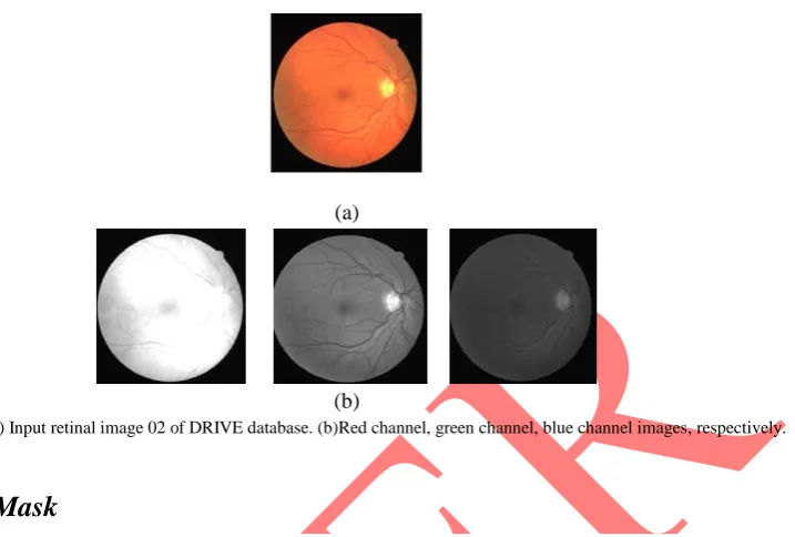
A. Channel Selection
(a)
(b)
Figure 2. (a) Input retinal image 02 of DRIVE database. (b)Red channel, green channel, blue channel images, respectively.
B. Fundus Mask
It is common knowledge that the fundus region has a high contrast with the black background in the image. So, a simple thresholding method known as otsu thresholding [8], which is a global threshold algorithm, is applied to detect the fundus region. After OTSU thresholding, a morphological closing is applied to erase small objects that may be left inside the fundus mask (see Figure 3.).
Figure 3. Fundus mask after morphological closing
Applying curvelet transform may cause artifacts outside of the fundus region, which results in false edges in the edge detection step. Therefore, presence of such mask, which indicates the fundus region, helps us to eliminate these artifacts. Moreover, this mask can decrease the computation time of the algorithm, because we can consider only the inside of fundus region instead of the whole image for applying subsequent steps in the algorithm.
C. Contrast Enhancement using FDCT
FDCT via wrapping method is applied on green channel, a set of scales Si with a set of
directional bands Di containing curvelet coefficients are obtained. Here 5 scales and 16 directions
, if |x| < ac
y(x) = , if ac ≤ |x| < m (5)
if |x| ≥ m
where x is the curvelet coefficient, 0 < p < 1 determines the degree of nonlinearity. k1 , k2 , and k3 are assigned weights which allow us to control the modification of coefficients with a higher severity. The adjustment parameter, a makes it possible to regulate the coefficients modification interval. Parameters c and m are involved in determining the coefficients modification interval as well as the amplitude of corresponding multiplying y. We choose c = σji , where σji is the noise
standard deviation of coefficients being in the same direction and same scale. m can be determined with regard to σji, as m = kσji . k is an additional and independent parameter from the curvelet
coefficient values. The assigned weights and adjustment parameter are experimentally tuned based on intrinsic characteristics of the input image and the goal of work thereby providing the required output.
The enhanced image containing modified coefficients are then reconstructed by Inverse Fast Discrete Curvelet Transform (IFDCT). In the enhanced images, some unrecognized thin vessels became easily recognizable. Also, use of statistic features of the coefficients (such as noise standard deviation) in the enhancement function allows us to make the function more adaptive to the input image.
It is found that, fusing the result of some ordinary contrast enhancement technique with the above result yields better accuracy. Let a1 denote the pixel value in the enhanced image obtained by some ordinary contrast enhancement technique and a2 denote the pixel value in the enhanced image obtained by applying FDCT. The method is as follows:
Find the pixel value of the enhanced (a1) and reconstructed image (a2). Fix the threshold value.
Compare each pixel of both the images and do the following:
If a1 and a2 are less than threshold, or greater than threshold, find mean value and replace.
If a1 is less than threshold and a2 is greater than threshold, replace with a2. If a2 is less than threshold and a1 is greater than threshold, replace with a1.
Figure. 4. Retinal image contrast enhancement. (a)-(c) Enhanced images using different selections of the enhancement function parameters.
The result of contrast enhancement is multiplied by the fundus mask and fed to the next stage. This removes artifacts, if any, present outside the fundus mask.
D. Blood vessel detection using bottom-hat morphology
The blood vessel edges are detected by means of bottom -hat transform via multistructure
elements morphology (see Figure 5.). Twelve different structuring elements with an angular resolution of 15º is used. They are applied on the bottom-hat edge detector function (5) and sub edges F(I)i are measured. The bottom-hat function produces an image with highlighted blood
vessels. The whole of detected edges are then calculated using the equation:
(6)
where F(I) is the whole edge image, M=180/ α gives the number of SEs where α is the required directional resolution and ωiis the weight assigned to each of the sub edge image [9].
(a) (b)
Figure 5. Results of edge detection for images 02 and 10 of DRIVE database.
E. False edges removal using morphological opening by reconstruction
In the resulting image of edge detection step, there are edges not belonging to blood vessels. To remove them, we use morphological opening by reconstruction. As mentioned earlier, opening by reconstruction includes two steps: conventional morphological opening and reconstruction by dilation. The performance of morphological opening by reconstruction can be improved, if we perform the opening using multistructure elements. The SEs used in this step is the same as in the edge detection step. Here, the maximum among the individual responsesis selected to construct the total image. This method allows us to eliminate the weak false edges. Later, reconstruction by dilation is accomplished using a flat structuring element such as a 3 × 3 square.
F. Guided filtering
(a) (b)
Figure 6. Combined results of false edge removal using morphological opening by reconstruction and guided filtering for images 02 and 10 of DRIVE database.
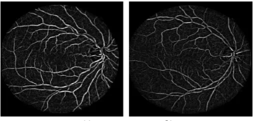
G. Length filtering
Next step is to remove the smaller disconnected regions. At first, the pixels in each connected region are calculated. Then, region connected to an area below a particular value is classified as non-vessel. The final segmented image is given in Figure 7.
(a) (b)
Figure 7. Result of length filtering for images 02 and 10 of DRIVE database.
EVALUATION
A. Enhancement assessment
One of the objective measures proposed is peak SNR (PSNR), which evaluates the intensity changes of an image between the original and the enhanced image. PSNR can be computed as
(7)
where MSE is the mean-squared error computed via
(8)
where Ioand Ieare the original and enhanced images, respectively.
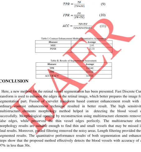
Algorithm performance is assessed using three measures: true positive rate (TPR), false positive rate (FPR), and accuracy (ACC). TP and TN show the blood vessel pixels and background pixels, which correctly detected, respectively. FP shows the pixels not belonging to a vessel, but is recognized as blood vessel pixels, and FN shows the pixels belonging to a vessel, but is recognized as background pixels, mistakenly. TPR, FPR, and Accuracy are defined as follows:
(9)
(10)
(11)
Table I. Contrast Enhancement Method Quantitative Assessment.
Measure Average
MSE 2.93
PSNR 32.33
Table II. Results of Segmentation Assessment.
Measure Average
TPR 0.8140
FPR 0.0128
ACCURACY 0.9710
CONCLUSION
Here, a new method for the retinal vessel segmentation has been presented. Fast Discrete Curvelet transform is used to enhance the edges in the retinal image, which better prepares the image for the segmentation part. Fusion of curvelet transform based contrast enhancement result with some ordinary contrast enhancement technique resulted in better result. The high sensitivity of multistructure elements morphology method helped in detecting the blood vessel edges successfully. Morphological opening by reconstruction using multistructure elements removed the false edges, while preserved the thin vessel edges perfectly. The multistructure elements morphology results are suitable enough to find thin and small vessels that may be missed in the final results. Moreover, guided filtering removed the noisy areas. Length filtering provided the final segmented results. The quantitative performance results of both segmentation and enhancement steps show that the proposed method effectively detects the blood vessels with accuracy of about 97% in less than 30s.
REFERENCES
[2] Saleh Shahbeig, ‖Retinal image analysis using multidirectional functors based on geodesic conversion‖, Turkish Journal of Electrical Engineering & Computer Sciences, 2014.
[3] Hoover, A., Kouznetsova, V., Goldbaum, M., ―Locating blood vessels in retinal images by piecewise threshold probing of a matched filter response‖, IEEE Transactions on Med Imag, Vol. 19, No. 3, 2000, pp. 203-210.
[4] E. J. Cand`es and D. L.Donoho, ―Curvelets—A surprisingly effective nonadaptive representation for objects with edges,‖ in Curves and Surfaces. Nashville, TN: Vanderbilt Univ. Press, 1999, pp. 123–143.
[5] E. Cand`es, L. Demanet, D. Donoho, and L. Ying, ―Fast discrete curvelet transforms,‖ Multiscale Model. Simul., vol. 5, no. 3, pp. 861–899, 2006.
[6] S. Mukhoopadhyay and B. Chanda, ―Multiscale morphological segmentation of gray-scale images,‖ IEEE Trans. Image Process., vol. 12, no. 5, pp. 533–549, May 2003.
[7]He, Kaiming,Sun, Jian ,Tang, Xiaoou, ―Guided image filtering‖ , IEEE Transactions on Pattern Analysis and Machine Intelligence, April 18, 2013.
[8] N. Otsu, ―A threshold selection method from gray level histograms,‖ IEEE Trans. Syst., Man, Cybern., vol. SMCA-9, no. 1, pp. 62–66, Jan. 1979.
[9] Y. Ma,M. Yang, and L. Li, ―A kind of omni directional multi-angle structuring elements adaptive morphological filters,‖ J. Chin. Inst. Commun., vol. 25, no. 9, pp. 86–92, 2004.