Analysis of Carrier Frequency Selective Offset
Estimation - Using Zero-IF and ZCZ
In MC-DS-CDMA
Venkatachalam. Karthikeyan
Department of ECE, SVSCE, Coimbatore, IndiaJeganathan. Vijayalakshmi.V
Department of EEE, SKCET, Coimbatore, IndiaAbstract—
A new method for frequency synchronization based upon Zero-Intermediate Frequency (Zero-IF) receiv-er and charactreceiv-eristics of the received signal’s powreceiv-er spec-trum for MC-DSCDMA-Uplink system is proposed in this paper. In addition to this, employing Zero Correlation Zone
(ZCZ) sequences, designed specifically for
quasi-synchronous uplink transmissions, is proposed to exploit frequency and temporal diversity in frequency-selective block-fading channels. The variance for Carrier Frequency Offset (CFO) estimators of MC-DS-CDMA Uplink is com-pared with that of an OFDM system to estimate the CFO. Our study and results show that the MC-DS-CDMA system is outperforming the OFDM method.
Index Terms
—
Carrier Frequency Offset (CFO), Zero-Intermediate Frequency (Zero-IF), Multi-Carrier Code Division Multiple AccessI. INTRODUCTION
Technological advances over the past two decades have led to the rapid evolution of the telecommunications industry. No longer limited to narrow-band voice signals, modern communications integrate voice, images, data, and video on a level that was once considered to be im-possible. Basically, in cellular systems there are four main methods of multiple access schemes such as FDMA, TDMA, CDMA, and OFDM. The main purpose of mul-tiple access schemes is used to achieve the following number of goals such as – to handle several numbers of users in the same channel without any mutual interfer-ence problem in it. Also, to maximize the range of the spectral efficiency and in addition to this its robustness, that is enabling the ease of handover/handoff between the cells. This OFDMA is based around OFDM which is a form of transmission use large number of close spaced carriers that are modulated with low rate data. Though
Manuscript received April 16, 2013; revised June 25, 2013
the signal is orthogonal to one another there will absence of mutual interference. The major advantage of OFDM signal is to avoid the effect of reflection and ISI over noisy channel. The carrier spacing is equal to the recipro-cal of the symbol period. To study and perform compara-tive analysis of carrier frequency offset estimation of two types of multiple access signals such as OFDM and MC-DS-CDMA. Furthermore, the proposed method is sim-pler to implement than the former methods for the reason that the correlation with the CP, the identical parts such as pilot carriers and the null carriers are not used.
II. ANALYSIS of CARRIER FREQUENCY OFFSET
The MC-DS-CDMA Ref. [14] is multiple access tech-niques for future networks physical layer due to its ability to support multiple access capability, robustness to fre-quency selective channels, high spectral efficiency and narrow band interference rejection. Our contribution is to suggest a coarse offset estimation scheme for MC- DS-CDMA system based on Zero-IF and on ZCZ sequence spreading codes Ref. [13]
A. MC-CDMA
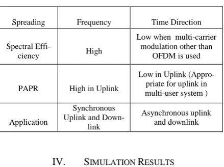
Multi-Carrier Code Division Multiple Access ( MC-CDMA) is a multiple access scheme used in OFDM-based telecommunication systems, allowing the system to support multiple users at the same time. In addition to this the table.1 clearly depicts the comparative analysis of various parameters like spreading, spectral efficiency, PAPR and application as shown in Table I.
B. MC-DS-CDMA
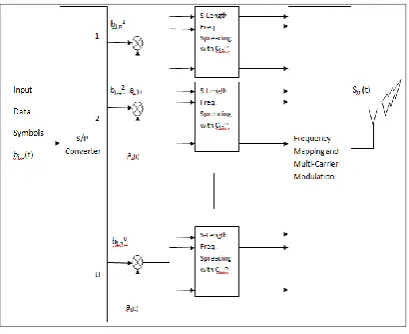
seri-al-to-parallel converted data stream is multiplied with the spreading sequence, and then the chips belonging to the same symbol modulate the same subcarrier. Here the spreading is done in the time domain. Thus this MC-DS-CDMA technique plays vital role in uplink transmission of wireless communication than any other access. The Transmitter section of this MC-DS-CDMA is given by the generalized block diagram shown in Figure.1 In TF-domain spreading MC-DS-CDMA, assume that there are J ZCZ time-domain spreading sequences available of length Q chips, i.e., aj(t) ( j = 0,….., J-1). Each
time-domain spreading sequence is associated with P frequen-cy-domain spreading sequences of length MBS , i.e., cj,p
( j = 0,…., P-1),
where S and MB are the number of frequency tones and
fading blocks over which frequency-domain spreading is done, respectively Ref. [10] Each user is assigned one time-domain spreading sequence aj (t) and one
frequen-cy-domain sequence cj,p. The maximum number of users
supported by TF-domain spreading MC-DS-CDMA is given by N = JP.
Figure 1. TF-domain spreading for MC-DS-CDMA
Fig.1 shows the transmitter schematic for a single-user in each fading block m. At the transmitter side, a symbol stream bj, p (t) with symbol period Tsym is serial to parallel
converted into U parallel branches in each fading block m. The above assumption implies that the coherence time (∆t) c of the channel is higher than but close to the symbol
duration of UTsym (i.e. (∆t) c ≥ UTsym). In this paper, we
refer to the symbol duration of UTsym as a fading block.
Note that, in practice, if the fading blocks are subject to correlated fading then interleaving may be employed over fading blocks at the transmitter, in order to guaran-tee the independent fading of the sub-carrier signals in each fading block. [10]Following time-domain spreading, the spread signal in each branch u is repeated on S paral-lel branches in each of MB fading blocks, where each parallel branch is multiplied by the corresponding chip value of a user-specific frequency-domain spreading se-quence cj,p = [cj,p[1], cj,p[2], …., cj,p[SMB]]τ . In this
anal-ysis it is assumed that the same set of frequency-domain spreading sequences are used for each branch u. The U.S X 1 transmission vector after time-domain and
frequen-cy-domain spreading for each user, in fading block m can be expressed in (1)
Zj,p,m =
, , ,1
, , ,2
, , ,
( )
( )
( )
mj p j j p
m
j p j j p
m
j p j j p U
c
t b
c
t b
c
t b
m=1,………,MB (1)
Where cj,pm = [cj,p[(m-1)S + 1], cj,p[(m-1)S + 2],…..,
cj,p[(m-1)S + S ]]τ , m = 1,…, MB.
The cyclic prefix insertion matrix is expressed as TCP = [IτCP IτU.S] τ, where CP is the cyclic prefix length.
The cyclic prefix removal matrix at the receiver can be expressed as RCP = [0U.SXCP IU.S]. The matrix γ is defined
as a U.S X U.S permutation matrix that maximally sepa-rates the data of each branch u in the frequency-domain, i.e., the (x,y)th element of is equal to 1 if x =
(y-1)mod(U).S + [(y-1)/U]+1 and equal to 0 otherwise. [9]The transmitter output for each user in each fading block m, from Fig.1, the transmitted signal can be ex-pressed in (2)
Sm (t) = TCP F
H U.S γ zj, p, m, m = 1… MB. (2)Where the above equation (2) represents the diagonal matrix of the channel frequency response in fading block m
C. Zero-IF Receiver
The zero-IF receiver, also known as a homodyne, syn-chrodyne or direct conversion receiver, is a special case of the super heterodyne receiver that uses an LO with the same frequency as the carrier. In Ref. [13] order for the detector to differentiate between signal components both above and below the LO frequency, zero IF receivers generate both In-Phase and Quadrature (IQ) signals. The following Fig. 2 which shows generalized block diagram of ZERO-IF receiver architecture. Further the main ad-vantages of preferring this receiver is nothing but, Lower complexity and power consumption (no IF amplifier, no IF band-pass filter, or no IF local oscillator), which has the potential to reach the ’one chip goal’ and No image frequency.
Figure 2. Zero-IF Receiver Architecture
Traditional orthogonal spreading sequences, such as orthogonal Gold sequences and Walsh-Hadamard se-quences, exhibit non-zero off-peak cross-correlations, which limits the achievable performance in asynchronous or quasi-synchronous scenarios. However, ZCZ sequenc-es exhibit an interference free window over which both the cross-correlation and autocorrelation function are zero Ref. [13]. Consequently, ZCZ sequences are able to suppress MUI in the quasi-synchronous uplink channel. We denote a set of ZCZ sequences as (Lseq, Mseq, Z0) -
ZCZ, where Lseq is the sequence length, Mseq is the
se-quence family size and Z0 is the one-sided ZCZ length in
chips. For a sequence set {sq(q=0)}Mseq with family size
Mseq, and sequence length Lseq, the periodic correlation
characteristics of ZCZ sequences are defined in (3) and (4)
]
s r
, ( )
iLseq0 1Sq l
[
]
mod Lseq
(
)
= (3)
And
Η = (4)
Here each sequence element sq[l] is a complex number
and Z0 is the ZCZ length in chips. The parameter η ≤ 1, is
only equal to one when every sequence element sq[l] has
unit amplitude, otherwise η < 1.. For a given ZCZ length, the theoretical upper bound is given in (5)
Z
0Lseq
1
Mseq
(5)The above expression suggests that to obtain a large ZCZ length, the sequence length Lseq needs to be
consid-erably larger than the family size Mseq. Thus, the
desira-ble properties of these sequences come at the cost of sup-porting only a small number of users, compared to other orthogonal sequences, such as Walsh-Hadamard se-quences Ref. [9] we will focus on the power spectrum of the signal Xlb (k) to estimating the blind carrier frequency
offset without any identical parts and without addition of any redundant data. The power spectrum, ρl (k), is given in (6)
ρ
l(
k
) = E [
X
l(
k
)
X
l *(
k
)]
(6)Where Xl*(k) is the complex conjugate of Xl (k).
In the MC-DS-CDMA, the modulation of each symbol is constant over Nf =N + NCPsamples, and e j(φi(n)−φi(m))
is a stationary process. Therefore, its expected value is calculated as given in (7)
E [ej (φi (n) – φi (m)] = φ (7)
III. RESULTS AND DISCUSSIONS
Figure 3 compares the variance theory of the CFO es-timator with simulations for MC-DS-CDMA and OFDM systems for a symbol of 256 samples, according to the length of the cyclic prefix NCP. Specifically, these
com-ponents are pattern-dependent self-noise and AWG channel noise. Figure 4 and Figure 5 compare the simu-lated and theoretical variances as a function of SNR. At high SNRs, there is again a difference of approximately 10% between the simulated and the theoretical variances for the majority of the simulations. At very low signal to noise ratios, this difference increases until the simulated variance is approximately 70% larger than the theoretical variance at an SNR. As the SNR increases, less im-provement in variance performance is observed in Figure 4 and Figure 5 which is consistent with the mathematical Variance expression as the contribution from the AWG component of the noise becomes overshadowed by the estimator self-noise. Figure 4 shows the effects of num-ber of symbols used to estimate the CFO at an SNR of 10dB. At all Nsymvalues, the variance of the CFO in
MC-DS-CDMA system is roughly 70% smaller than the OFDM variance and roughly 10% larger than the theoret-ical variance. Fig 5 shows the effects of the AWGN component in variance of the CFO as a function of SNR. At very low SNR (< 10 dB), the variance is approximate-ly larger than the theoretical variance, but is smaller than the OFDM variance, while for SNRs above 10dB, the theoretical variance predicts the observed simulated. Fig-ure 5 shows the performance results using the optimal ML detector and the MMSE block linear detector at the receiver. One observes from Figure 6 that there is an ap-proximate 2.7 dB performance improvement for the op-timal ML detector at a BER of 10-4 to 10-5.
TABLE I. COMPARISONS OF MC-CDMA AND MC-DS-CDMA Spreading Frequency Time Direction Spectral
Effi-ciency High
Low when multi-carrier modulation other than
OFDM is used PAPR High in Uplink
Low in Uplink (Appro-priate for uplink in multi-user system ) Application
Synchronous Uplink and
Down-link
Asynchronous uplink and downlink
IV. SIMULATION RESULTS
Simulations are carried out to investigate the perfor-mance of the system by choosing BER as a figure of mer-it. In the simulations, the channel coefficients are con-stant during one symbol block duration (i.e. UTsym), but
Owing to the additional temporal diversity exploited in block fading conditions.
Figure 3. NCP for a symbol of 256 samples
Figure 4. Effects of Number of symbols
Figure 5. Effects of AWGN
Figure 6. Performance of BER Vs Number of symbols
V. CONCLUSION
Thus the objective of this project work was to develop and to analyze an algorithm for blind CFO recovery suit-able for use with a practical zero-IF OFDM telecommu-nications system [14]. MC-DS-CDMA is more sensitive to carrier frequency offsets than other modulation tech-niques like QAM. CFOs significantly degrade the SNR at the output of the receiver.
REFERENCES
[1] S. Suwa, H. Atarashi, and M. Sawahashi, “Performance compari-son between MC/DS-CDMA and MC-CDMA for reverse link broadband packet wireless access,” IEEE Transactions on Signal Processing, vol. 03, pp. 7803-7467, 2002
[2] C. Langton, “Intuitive guide to principles of communication,”
IEEE Transactions of Comm. Dec. 2005.
[3] M. Li and W. Zhang, “A novel method of carrier frequency off-set estimation for OFDM systems,” IEEE Transactions on Con-sumer Electronics, vol. 49, pp. 965–972, Nov. 2003.
[4] H. Wei, L. L. Yang, and L. Hanzo, “Time- and frequency-domain spreading assisted MC DS-CDMA using interference re-jection spreading codes for quasi-synchronous communications,” in Proc. of IEEE VTC, vol. 1, no. 26-29, Sep. 2004, pp. 389–393. [5] H. Steendam and L. Hanzo, “Performance of broadband
multi-carrier DS-CDMA using space-time spreading-assisted transmit diversity,” IEEE Trans. on Wireless Comm., vol. 4, no. 3, pp.885–894, May 2005.
[6] L. Liu and X. Dai, “Pilot aided carrier frequency offset estima-tion in MC-DS-CDMA systems,” IEEE Trans. on Wireless Comm., 2008
[7] X. Wang, “Linear Zero-IF direct conversion receiver,” IEEE Trans. on Consumer Electronics, Dec 2008.
[8] S. Philip, “Multi-carrier systems,” WITS lab, NSYSU, 2006. [9] Jean-Paul M.G. Linnartz, “The basics of code division multiple
access,” IEEE the Global Telecommunications Conference, 2007. [10] S. A. B. Mustafa and S. N. Qadir, “Performance comparison of OFDMA and MC-CDMA over wireless channel.” 5th Interna-tional Advanced Technologies Symposium(IATS’09), May 2009, Karabuk, Turkey.
[11] F. Classen and H. Meyr, “Frequency synchronization algorithms for OFDM systems suitable for communication over frequency selective are fading channels,” in Proceedings IEEE the Global Telecommunications Conference, vol.3, 1994, pp. 1655-1659. [12] Y. J. Huang and S. W. Wei, “Modified guard band power
Ve-hicular Technology Conference volume 4, Oct 2003, pp. 2277– 2281.
[13] M. Mitzel and M. Salt, “Carrier frequency offset recovery for a zero-IF OFDM receiver”, IEEE CCECE/CCGEI, Saskatoon, May 2005.
[14] A.B. Djebbar, K. Abed-Meraim, and A. Djebbari, “Blind channel equalization and carrier frequency offset estimation for MC-CDMA systems using guard interval redundancy and excess codes,” Int. J. Electron. Commun. pp. 220-225, 2009
Venkatachalam. Karthikeyan has received his
Bachelor’s Degree in Electronics and Communica-tion Engineering from PGP college of Engineering and technology in 2003 Namakkal, India. He re-ceived Masters Degree in Applied Electronics from KSR college of Technology, Erode in 2006. He is currently working as Assistant Professor in SVS
College of Engineering and Technology, Coimbatore. He has about 7 years of teaching Experience.
Jeganathan. Vijayalakshmi has completed her