Copyright © 2012 IJECCE, All right reserved 1257
Speed Control of BLDC Motor using Soft Computing
Technique and its Stability Analysis
Bikram Das, Suvamit Chakraborty, Prabir Rn. Kasari, Abanishwar Chakraborti, Manik Bhowmik
Abstract — The objective of this paper is to build a speed control technique for brushless DC (BLDC) machine, study the performance of the same motor under different speed and load torque conditions and finally to analyze the stability of the BLDC motor by using different stability criterion. Here a soft computing technique PSIM is used for the simulation of the BLDC motor and the PID controller has been developed in MATLAB which is then linked with PSIM using the SIMCOUPLER for controlling the generation of the variable gate pulse for the voltage source inverter (VSI).The simulation results of BLDC motor performance shows that it gives good results of speed control which can critically evaluated under various input parameters in the PSIM environment. The accuracy of this approach can also be verified by comparing the simulation results in PSIM with the results of the response obtained from the BLDC motor.
Keywords — BLDC motor, VSI, PID controller, stability
analysis, PSIM, MATLAB.
I.
I
NTRODUCTIONThe use of permanent magnets (PMs) in electrical machines in place of electromagnetic excitation results in many advantages such as no excitation losses, simplified construction, improved efficiency, fast dynamic performance, and high torque or power per unit volume. The PM excitation in the early 19th century was not adopted due to the poor quality of PM materials. In 1932, the invention of Alnico revived the use of PM excitation systems, however it has been limited to small and fractional horse power dc commutator machines [1].
Squirrel cage induction motors (SCIM) have been the most popular electric motors, due to its rugged construction in the 20th century. Motor drives have become more prevalent in industrial installations due to the advances in the field of power electronics and DSP. However, SCIM suffer from poor power factor and efficiency as compared to synchronous motors. On the other hand, synchronous motors and dc commutator motors have limitations such as speed, noise problems, wear and EMI due to the use of commutator and brushes. These problems have led to the development of permanent magnet brushless (PMBL) or commutatorless synchronous motors which have PM excitation on the rotor [1].
Therefore, PMBL motors can be considered a kind of three phase synchronous motor, having permanent magnets on the rotor, replacing the mechanical commutator and brush gear. Commutation is accomplished by electronic switches, which supply current to the motor windings in synchronization with the rotor position. Therefore, PMBL motors can be considered a kind of three phase synchronous motor, having permanent magnets on the rotor, replacing the mechanical
commutator and brush gear. Commutation is accomplished by electronic switches, which supply current to the motor windings in synchronization with the rotor position [1].
Brushless dc (BLDC) motor drives are becoming widely used in various consumer and industrial systems, such as servo motor drives, home appliances, computer peripherals, and automotive applications. Consequently, many machine design and control schemes have been developed to enhance the performance of BLDC motor drives. In general, the overall system consists of three parts: (i) power conversion PWM inverters, (ii) BLDC motor and load, and (iii) speed, torque, and current controller. Therefore, exact understanding of each part is a prerequisite for analysis and prediction of the overall system operation. Before now, several simulation models have been proposed for the analysis of BLDC motor drives. These models are based on state-space equations, Fourier series, and the d-q axis model [2]. In this paper we propose a simulation model for an entire BLDC motor drive to obtain controlled speed and also to analyze the stability of the complete system [3].
II.
P
RINCIPLE ANDC
ONSTRUCTION BLDC motors are a type of synchronous motor. This means the magnetic field generated by the stator and the magnetic field generated by the rotor rotates at the same frequency. BLDC motors do not experience the “slip” that is normally seen in induction motors. BLDC motors come in 1-phase, 2-phase and 3-phase configurations. Corresponding to its type, the stator has the same number of windings. The 3-phase motors are the most popular and widely used [4].The analysis is based on the following assumptions for simplification.(i)The motor is not saturated (ii) Stator resistances of all the windings are equal, and self- and mutual inductances are constant (iii) Power semiconductor devices in the inverter are ideal (iv) Iron losses are negligible. Among the above-mentioned assumptions, the iron loss can be approximated using empirical equations, and the dynamic characteristics of the switching devices need to be considered for the investigation of transient state behaviour [3].
Copyright © 2012 IJECCE, All right reserved There are two types of stator windings variant-
trapezoidal and sinusoidal motors. This differentiation is made on the basis of the interconnection of the coils in the stator windings to give the different types of back EMF.
Fig.1. Stator of BLDC motor
The rotor is made of permanent magnet and can vary from two to eight pairs with alternate North (N) and South(S) poles. Based on the required magnetic field density in the rotor, the proper magnetic materials are chosen to make the rotor [5]. The fig.2 below shows the Cross sections of the different arrangements of the rotor.Fig.3 shows the transverse section of the BLDC motor along with the position of the hall sensors.
Fig.2. Cross sections of the different rotor arrangement
Fig.3. BLDC motor transverse section
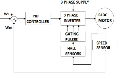
Fig. 4 below shows the BLDC motor drive system which is the proposed system being used in this paper by generating PID controller part in the Matlab environment. The fig. 5 shows the BLDC motor with the converter circuit.
Fig.4. Block diagram for BLDC speed control system.
Fig.5. BLDC motor with converter circuit
III.
BLDC
M
OTORM
ODELINGThe Y -connected, 3-phase motor with a 4-pole permanent magnetic rotor is driven by a PWM inverter. The rotor position, which determines the switching sequence of the IGBT transistors, is detected by means of 3 Hall sensors mounted on the stator. The switching scheme implemented in the inverter logic is well-known.
The model equations of a BLDC motor are composed of a voltage equation, a torque equation and a motion equation. The stator of a general BLDC motor has three windings like an induction motor or a permanent magnet synchronous motor [6].The equivalent circuit diagram of the stator winding is as shown in fig.6.
Figure 6 .Equivalent circuit daigram stator winding
The equations of the 3-phase brushless dc machine are as below
(1)
(2)
(3)
Where Va, Vb, and Vc are the phase voltages, Ia, Ib, and
Ic are the phase currents, R, L are the stator phase resistance, self inductance and Ea, Eb and Ec are the back
emf of phase A, B, and C, respectively. The back emf voltages are functions of the rotor
mechanical speed and the rotor electrical angle θr, that is
(4)
(5)
(6) The coefficients Ka, Kb, and Kc are dependent on the
Copyright © 2012 IJECCE, All right reserved 1259
(7) Where B is a coefficient, Tl is the load torque, and P is
the no. of poles. The coefficient B is calculated from the moment of inertia J and the mechanical time constant Tm as below.
(8)
(9)
IV.
C
ONTROL OFBLDC
M
OTOR
The control of PMBLDC motors can be accomplished by various control techniques using conventional six pulse inverters which can be classified in two broad categories as voltage source inverter (VSI) and current source inverter (CSI) based topologies. The controllers can further be divided on the basis of solid state switches and control strategies. The PMBLDCM needs rotor-position sensing only at the commutation points, e.g., every 60°electrical in the three-phases; therefore, a comparatively simple controller is required for commutation and current control. The commutation sequence is generated by the controller according to the rotor position which is sensed using Hall sensors, resolvers or optical encoders. These sensors increase the cost and the size of the motor and a special mechanical arrangement is required for mounting the sensors.
BLDC motors have become a popular choice in many applications due to ease of control, low system cost and good torque control performance. They also have high power density and are capable of highly efficient operation since the main flux is produced by permanent magnets. Therefore, the study of BLDC motors has been a topic of interest for many researchers [6].
A circuit analysis of the inverter is also a major part of the simulation of a BLDC motor system. The current path of a BLDC motor is changed by six conduction intervals and the switching pattern of the inverter, so that the model of a BLDC motor has to be reconfigured to reflect the change in current path. Due to such complex set-up processes, the model of a BLDC motor tends to be fixed to one switching pattern in most of the existing papers.
For proper operation of a PMBLDC motor, the flow of current in the stator windings must be synchronized to the instantaneous position of the rotor and therefore, the current controller must receive information about the position of the rotor. However, the presence of the position sensor is undesirable in many applications; therefore, position sensor less schemes may be employed in which rotor position information is deduced from the voltages and currents in the motor windings [1].
V.
S
IMULATION OFBLDC
INPSIM
A 3-phase brushless dc motor is taken in PSIM for simulation purpose with trapezoidal waveform back emf.
In fig. 3, nodes a, b, and c are the stator winding terminals for phase A, B, and C, respectively. The stator windings are Y connected, and Node “n” is the neutral point. The shaft node is the connecting terminal for the mechanical shaft. They are all power nodes and should be connected to the power circuit. Node Sa, Sb, and Sc are the outputs of
the built-in 6-pulse hall effect position sensors for phase A, B, and C, respectively. The sensor output is a bipolar commutation pulse (1, 0, and -1). The sensor output nodes are all control nodes and should be connected to the control circuit [5].With the help of a Sim coupler we could add together the two software package. The controller part consisting of PID, second order low pass filter, generation of PWM signals has been developed by using the Matlab.
Fig.7. BLDC drive circuit in PSIM
Fig.8. Matlab block diagram of PID controller.
Table I shows the values of the different parameters used for the simulation of BLDC in PSIM alongwith the use of Matlab for building the PID controller which has been again connected with the PSIM using the Simcoupler.
The fig. 7 shows a brushless dc motor drive system with speed feedback in Psim environment. The motor is fed by a 3-phase voltage source inverter.
Table I .BLDC Motor Parameters
R(stator resistance) in ohms 9.7
L(stator self inductance) in H 0.11E-3
M(stator mutual inductance) in H -0.44E-3
No. of poles P 8
Moment of Inertia in Kg m^2 31.05E-006
Mechanical Time Constant 3.4e-03
Theta_advance(deg.) 0
Copyright © 2012 IJECCE, All right reserved 1260
Terminal Voltage volts 24
Current rating in A 12.67
Power rating in watts 262.4
Speed rating in rpm 929
The outputs of the motor Hall Effect position sensors are used as the gating signals for the inverter, results to a 6-pulse operation. The speed control is achieved by modulating sensor commutation pulses (Vgs for Phase A in this case) with another high frequency pulses (Vgfb for Phase A) [7].The high-frequency pulse is generated from a dc current feedback loop. The DC voltage is applied to the BLDC motor which is converted into three phase AC by use of inverter. The three phase inverter circuit consists of six IGBT’s which converts DC to AC .Three current probes are connected through each phase to obtain the wave form of the current in each phase. The outputs of the motor Hall Effect position sensors are used as the gating signals for the inverter’s IGBT’s [4]. The simulation processes have been combined with Matlab to give more accurate results. The fig.8 shows the Matlab implementation where PID controllers are used to finally generate the firing pulses to control the speed of the BLDC motor.
VI.
C
ALCULATIONSThe calculations for the various data of BLDC motor has been done as below. The motor voltage constant, Ke is calculated as –
Back emf constant
Torque Sensitivity=
Te = Electrical time constant
Tm=Mechanical time constant
The open loop transfer function of the bldc motor is given
by
Open loop characteristics
Performing Routh stability criteria;
So using a trail & error method the PID constants are chosen as shown in table II.
Table II. Parameters in the PID controller
P (Proportional constant) 40.65
I (Integral Constant) 4060.5
D (Derivative Constant) 0.0246
VII.
R
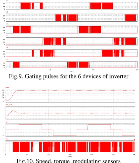
ESULTSThese results were obtained by running the PSIM [9] and Matlab [10]. The fig. 9 below shows the six gating pulses for the devices of the voltage source inverter (VSI).The fig.10 shows the Speed, torque ,modulating sensors commutation pulses and high frequency pulses for generating the gating pulses as shown in fig.9.The output of the 3 Hall effect sensors connected for sensing the position of the rotor of the BLDC motor is shown in fig. 11.
The results of other parameters like voltage across the switch, current wave form of the Hall Effect sensor etc. can also be obtained by adding these parameters in SIMVIEW. The simulation waveforms show the start-up transient of the mechanical speed (in rpm), developed torque Tem etc.
Fig.9. Gating pulses for the 6 devices of inverter
Fig.10. Speed, torque ,modulating sensors commutation pulses and high frequency pulses.
Fig.11.Output of the 3 Hall effect sensors
Copyright © 2012 IJECCE, All right reserved 1261
but this error is very less. Table III shows the results for 1000 rpm speed.
The result shown fig.13 reveals that the speed starts from zero rpm then goes negative for a small time and then when it attains the steady state it seems that the speed remains less than the reference speed of 500rpm.So, in both cases there remains an error but that is very less. Table IV shows the results for 500rpm speed.
Fig.12. Currents, torque and speed curve at 1000 reference speed and 0.5 load torque
Table-III. Results of simulation
SL. No Measurements Rating
1 DC Voltage 24V
2 Speed 950rpm
3 Electromagnetic Torque 1.5N-m
Fig.13. Currents, torque and speed curve at 500 reference speed and 0.5 load torque
TABLE-IV RESULTS OF SIMULATION
SL. No Measurements Rating
1 DC Voltage 24V
2 Speed 485rpm
3 Electromagnetic Torque 1N-m
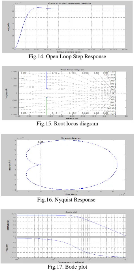
The fig. 14 shows the open loop step response for the drive system. After that I have gone to analyse the stability of the BLDC motor by using different techniques like Root Locus, Nyquist stability analysis and lastly the bode plot for the same system with the values of the parameters used for the simulation of BLDC in PSIM.
Fig.14. Open Loop Step Response
Fig.15. Root locus diagram
Fig.16. Nyquist Response
Fig.17. Bode plot
The stability analysis of the BLDC motor has been carried out to study the suitability of the motor for application in different fields.Fig.15 shows the Root locus diagram that shows that the system is absolutely stable for all values of gain.Fig.16 and fig.17 also shows that the motor is absolutely stable for operation with any values of gain. Finally I can say that the BLDC motor simulated in PSIM is absolutely stable for all types of closed loop applications.
VIII.
C
ONCLUSIONSCopyright © 2012 IJECCE, All right reserved PID controller is generated in Matlab. Then it shows that
the BLDC motor can be used with the configuration as described in this paper for any kinds of closed loop operation. In this model it is seen keeping the load torque fixed and varying the reference speed a little error is encountered that is within the tolerance limit. The combined simulation results of this paper have proposed the use of commercially available software packages to study the performance of BLDC motor. The results of simulation model gives help in building hardware with expected results. The simulation saves time and manpower in making hardware models at initial stages and reduces the costing of the research work.
A
CKNOWLEDGMENTI would like to thank everybody who has helped me directly or indirectly in completing the above work.
R
EFERENCES[1] Bhim Singh, Sanjeev Singh.”State of the Art on Permanent
Magnet Brushless DC Motor Drives” Journal of Power
Electronics, Vol. 9, No. 1, January 2009.
[2] Rakesh Saxena,Yogesh Pahariya,Aditya Tiwary ”Modeling and
Simulation of BLDC Motor Using Soft Computing Techniques” 2010 Second International Conference on Communication
Software and Networks
[3] B. K. Lee and M. Ehsani “Advanced Simulation Model for
Brushless DC Motor Drives” Electric Power Components and Systems, 31:841–868, 2003
[4] R. Dhanasekaran, J. Karthikeyan ”Simulation and
implementation of current control of BLDC motor based on a common DC signal” International Journal of Engineering Science and Technology Vol. 2(6), 2010, 1632-1639.
[5] Brushless DC (BLDC) Motor Fundamentals Author: Padmaraja
Yedamale 2003 Microchip Technology Inc. Application note.
[6] Yongjin Kang and Ji-Yoon Yoo “Switching Pattern-Independent
Simulation model for Brushless DC Motors”.JPE 11-2-8
[7] PSIM User’s Guide Version 6.1 Release 3 February 2005.
[8] Simulation software-Powersim\PSIM9.0.4_Network
[9] Simulation software-MATLAB 7.8.0(R2009a).
A
UTHOR’
SP
ROFILEBikram Das
Bikram Das [[email protected]]
was born in Udaipur, Tripura, India in 1981. He received his Bachelor Degree in Electrical Engineering from the University of Tripura, Agartala in 2003and Master degree in Power
Electronics & Drives from NIT, Agartala, Deemed University in the year 2010. He is working as Assistant Prof. in with the Department of
Electrical Engineering, in NIT, Agartala. His research interest is in the field of power electronics and drives, Energy sources, Special Electrical machines.
Suvamit Chakraborty
Suvamit Chakraborty [[email protected]]
was born in Kolkata, W. Bengal in 1987.He
received his B.Tech degree in Electrical
Engineering from West Bengal University Of Technology, Kolkata in the year 2010. He is
presently pursuing hisM.Tech from National Institute Of Technology,
Agartala in Power Electronics & drives. His area of interest include Power electronics & Electrical machines.
Prabir Ranjan Kasar
Prabir Ranjan Kasari[[email protected]]
was born in Udaipur, Tripura, India in1983. was born in He received the Bachelor degree in
Electrical Engg. from NERIST in 2005 and the Master degree in Power System from Tripura University, Agartala, in the year 2007. He is currently working as Assistant prof. with the Department of Electrical Engineering, in NIT, Agartala. His research interest is in the field of Power System and
FACTs
.
Abanishwar Chakraborti
A
.
Chakraborti [[email protected]]was born in Agartala, Tripura, India in 1980. He
received the Bachelor degree in Electrical Engg. from NERIST in 2004 and the Master degree in Control System Engineering from IIT, Kharagpur.
He is currently working as Assistant professor
with the Department of Electrical Engineering
His research interest is in the field of Control System Power Electronics and Drives.
Manik Bhowmik
Manik Bhowmik [[email protected]]
was born in Udaipur, Tripura, India in 1974. He received the Bachelor degree in Electrical Engg. from the Andhra University in 1997 and the Master degree in Micro-Wave Engineering