Doctoral Thesis
Dirac Plasmon Polaritons
Author:
Thomas Michael Jebb Sturges
Supervisors: Dr. Eros Mariani Prof. BillBarnes
A thesis submitted in fulfilment of the requirements for the degree of Doctor of Philosophy in Physics
in the
Quantum Systems and Nanomaterials group Department of Physics and Astronomy
Declaration of Authorship
This text entitled ‘Dirac Plasmon Polaritons’ is submitted by Thomas Michael Jebb Sturges to the University of Exeter as a thesis for the degree of Doctor of Philosophy in Physics, in July 2017.
This thesis is available for Library use on the understanding that it is copyright material and that no quotation from the thesis may be published without proper acknowledge-ment.
I certify that all material in this thesis which is not my own work has been identified and that no material has previously been submitted and approved for the award of a degree by this or any other University.
Signed:
Date:
UNIVERSITY OF EXETER
Abstract
College of Engineering, Mathematics and Physical Sciences Department of Physics and Astronomy
Doctor of Philosophy in Physics
Dirac Plasmon Polaritons
by Thomas Michael Jebb Sturges
We study theoretically graphene-like plasmonic metamaterials, in particular a honey-comb structured array of identical metallic nanoparticles, and examine the collective plasmonic modes that arise due to the near-field dipolar coupling between the localised surface plasmons of each individual nanoparticle. An analysis of the band structure of these eigenmodes reveals a phenomenal tunability granted by the polarisation of the dipole moments associated with the localised surface plasmons. As a function of the dipole orientation we uncover a rich phase diagram of gapped and gapless phases, where remarkably every gapless phase is characterised by the existence of collective plasmons that behave as massless chiral Dirac particles, in analogy to electrons in graphene. We consider lattices beyond the perfect honeycomb structure in two ways. Firstly, we break the inversion symmetry which leads to collective plasmons described as massive chiral modes with an energy dependent Berry phase. Secondly, we break the three-fold rotational symmetry and investigate generic bipartite lattices. In this scenario we progressively shift one sublattice away from the original honeycomb arrangement and observe a sequence of topological phase transitions in the phase diagram, as well as the merging and annihilation of Dirac points in the dispersions. After examining the purely plasmonic response we wish to address the true eigenmodes responsible for trans-porting electromagnetic radiation. For this reason we examine plasmon polaritons that arise from the strong light-matter coupling between the collective plasmons in a honey-comb array of metallic nanoparticles and the fundamental photonic mode of an enclosing cavity. Here we identify that the Dirac point remains robust and fixed in momentum space, irrespective of the light-matter coupling strength. Moreover, we demonstrate a qualitative modification of the polariton properties through modulation of the photonic environment, including order-of-magnitude renormalisation of the group velocity and the intriguing ability to invert the chirality of Dirac polaritons.
Acknowledgements
There are many to whom I am grateful. Firstly on a formal level, I would like to thank my host institution the University of Exeter and the various support staff who have aided with multiple queries. For financial support I acknowledge the College of Engineering, Mathematics and Physical Sciences for granting me a College Research Studentship, funded by the Engineering and Physical Sciences Research Council. I am also grateful for the hospitality of the Condensed Matter Physics Group at the University of Chalmers, as well as the organisers of the Frontiers of Condensed Matter 2015 and L’ ´Ecole de Physique des Houches. I would also like to sincerely thank Prof. Bill Barnes for providing me with the opportunity to undertake this PhD, and for the complete academic freedom to pursue my own interests.
I am indebted to Dr. Eros Mariani — who saved me from the brink of a career in engineering. It was a happy accident that I was placed under the guidance of Eros for my Master’s project. However, because of his infectious enthusiasm and ability to explain deep ideas with sparkling clarity, I thoroughly enjoyed the research and was inspired to continue as a PhD student with him as my supervisor. The experience has been invaluable and I would like to express my deepest gratitude to Eros for the significant effort he has invested in preparing me for a career in scientific research. A special mention needs to be made to each of my co-authors: Dr. Claire Woollacott, Prof. Guillaume Weick and Charlie-Ray Mann. Claire was a de facto supervisor as I transitioned from Master’s student to PhD student, and has provided me with so much support and guidance over the years. Guillaume made significant contributions to my understanding of our research, and is a wonderfully ruthless editor of manuscripts. The newcomer PhD student Charlie has made critical contributions to the direction, and hopefully success, of our research. Thanks to all three of you!
I have enjoyed discussions and guidance from many of my colleagues. In particular I would like to acknowledge: Prof. Misha Portnoi — for advice on many issues such as career trajectories, Dr. Thomas Philbin — for helpful discussions about cavity QED, Dr. Ian Hooper — for IT support and discussions about numerics and simulations, Prof. Saverio Russo — group leader extraordinaire, Dr. Thomas Constant — for help with COMSOL, Prof. Gyaneshwar Srivastava — for help and guidance on many issues, and Dr. Alastair Humphrey — for showing me the lab and a real live nanoparticle! In addition I am very grateful to the other Mariani group members, Dr. Hai-Yao (Frank) Deng and Thomas McDermott, who have entertained many a question of mine.
To my friends and peers — Robin Churchill, Dr. Lachlan Marnham, Dr. Charles Downing, Dr. Vasil Saroka, Thomas Collier, Dr. Arseny Alexeev, Dr. Alex Pearce,
iv
Ned Taylor and Natalie Whitehead — thank you for the laughs and comradeship. In particular I would like to thank Charles for his advice on issues scientific and otherwise, and who I have co-opted as a mentor of sorts.
I am thankful to Dr. Marcin Mucha Kruczynski and Dr. Steven Hepplestone for agreeing to examine this thesis, and to Prof. Gyaneshwar Srivastava for assuming the role of independent chair.
Most importantly, I say thank you to my amazing parents Karen & Bill, and my brother Iain. I have the best family one could wish for, and they have cheered me on, lifted my spirits, and kept me approximately sane throughout my PhD.
My final thank you goes to Karina, my best friend. I’m not sure I could have done it without you.
Contents
Declaration of Authorship i
Abstract ii
Acknowledgements iii
Contents v
List of Figures viii
Abbreviations x 1 Introduction 1 2 Introduction to plasmonics 6 2.1 Plasmonics . . . 7 2.1.1 Electromagnetics . . . 7 2.1.2 Plasma model. . . 9 2.1.3 Volume plasmons . . . 11 2.1.4 Surface plasmons . . . 12
2.2 Localised surface plasmons . . . 14
2.2.1 Eigenmodes of a spherical nanoparticle. . . 15
2.2.2 Electronic centre-of-mass decomposition . . . 17
2.2.3 Effects of size, shape and material . . . 19
2.2.4 Damping mechanisms . . . 23
2.3 Arrays of metallic nanoparticles . . . 24
2.4 Polaritons . . . 29
2.4.1 Hopfield and the strong coupling regime . . . 29
2.5 Chapter Summary . . . 33
3 Introduction to graphene 35 3.1 Geometric phases and related concepts . . . 36
3.1.1 The geometric phase . . . 37
3.1.2 Berry curvature and Chern number. . . 39
3.1.3 Berryology in the Brillouin zone . . . 40
3.1.4 Dirac points. . . 41
Contents vi
3.1.5 Berryology in a two-band model . . . 42
3.2 Electronic structure of graphene . . . 44
3.2.1 Tight Binding Model of Graphene . . . 45
3.2.2 Massless Dirac fermions . . . 48
3.3 Consequences of chirality . . . 50
3.3.1 Suppression of elastic backscattering . . . 50
3.3.2 Klein tunneling . . . 51
3.4 Pseudo-magnetic gauge fields . . . 55
3.4.1 Modification of model due to strain . . . 55
3.4.2 Landau quantisation in zero magnetic field . . . 56
3.5 Chapter Summary . . . 57
4 Dirac plasmons in bipartite lattices of metallic nanoparticles 59 4.1 Model . . . 60
4.1.1 Model of a nanoparticle dimer . . . 61
4.1.2 Linear chain. . . 65
4.2 Perfect honeycomb lattice of identical nanoparticles. . . 68
4.2.1 Model . . . 68
4.2.2 Exact diagonalisation . . . 71
4.2.3 Dirac-like collective plasmons . . . 74
4.2.4 The topology of polarisation-space and Dirac point merging . . . . 76
4.2.5 Highly tunable spectrum. . . 81
4.2.6 Inversion asymmetry and an energy dependent Berry phase . . . . 84
4.2.7 Interactions past nearest-neighbours . . . 86
4.3 Arbitrary bipartite hexagonal array. . . 89
4.4 Chapter Summary . . . 93
5 Dirac plasmon-polaritons in nanoplasmonic arrays 95 5.1 Polaritonic Hamiltonian and spectrum . . . 96
5.1.1 Quantised cavity modes . . . 97
5.1.2 Light-Matter Hamiltonian . . . 100
5.1.3 Exact diagonalisation . . . 102
5.1.4 Polaritonic dispersion . . . 104
5.2 Dirac-like collective plasmon polaritons. . . 108
5.2.1 Effective Hamiltonian in the plasmonic subspace . . . 109
5.2.2 Topological transition at critical cavity height . . . 113
5.2.3 Second order expansion around the degeneracy point . . . 116
5.3 Summary . . . 121
6 Dirac plasmons in a pseudo-magnetic field 123 6.1 Modification of model due to strain. . . 123
6.1.1 Graphene-like case . . . 125
6.1.2 Arbitrary polarisation . . . 127
6.2 Summary . . . 128
Contents vii
A Derivation of dispersion relation for surface plasmon polaritons 135 B Arbitrarily orientated dipoles: Anisotropic nanoparticles 139 B.1 Eigenmodes of a dimer of spherical nanoparticles . . . 139
B.2 Eigenmodes of a dimer of spheroidical nanoparticles . . . 141
C Videos 146
List of Figures
2.1 Photo of an engraving of Maxwell’s equations . . . 8
2.2 Dispersion of electromagnetic modes within a Drude metal. . . 10
2.3 The Drude model fitted to data for the dielectric function of silver . . . . 11
2.4 Dispersion of surface plasmon polaritons . . . 13
2.5 Schematic of a nanosphere and the environment. . . 16
2.6 Eigenfrequencies of localised surface plasmons in nanospheres . . . 17
2.7 Temperature dependence of the absorption spectra for gold nanoparticles 20 2.8 Plot of plasmon resonance as a function of shape and size . . . 21
2.10 Dark-field images and spectra of nanoparticles with different shapes . . . 22
2.11 Numerically calculated extinction spectra of oblate spheroids . . . 23
2.12 Schematic of the eigenmodes of a nanoparticle dimer . . . 25
2.13 The dependence of peak resonant wavelength of an array on the lattice spacing . . . 27
2.14 Plasmon resonance energies for linear arrays with various lengths . . . 28
2.15 Polaritonic dispersion of an infinite classical dielectric . . . 33
3.1 Visualisation of the calculation of the Berry phase . . . 44
3.2 The lattice structure and Brillouin zone of graphene . . . 45
3.3 Band structure and Berry curvature of graphene . . . 47
3.4 Schematic of Klein tunneling at normal incidence . . . 52
3.5 Transmission probability through a step barrier potential . . . 54
4.1 Schematic of an eigenmode of a dimer of anisotropic nanoparticles . . . . 63
4.2 Polarisation dependent eigenfrequencies of a nanoparticle dimer . . . 65
4.3 Schematic of the eigenmodes of a linear nanoparticle chain. . . 66
4.4 Dispersion of a linear chain of nanoparticles . . . 68
4.5 The honeycomb structured lattice and corresponding Brillouin zone . . . 70
4.6 Plasmonic dispersion of honeycomb array for θ= 0 . . . 74
4.7 Phase diagram of gapped and gapless dispersions in polarisation space . . 78
4.8 Evolution of the dispersion as Dirac points merge . . . 80
4.9 Phase diagram showing minimum gap of dispersions in polarisation space 81 4.10 Plasmonic dispersions for various polarisation orientations . . . 83
4.11 Additional plasmonic dispersions for various polarisation orientations. . . 83
4.12 Dispersions of honeycomb structure with broken inversion symmetry . . . 85
4.13 The effect of including further neighbours on plasmonic dispersion . . . . 88
4.14 Schematic of a generic hexagonal bipartite lattice . . . 90
4.15 Topological transitions of phase diagram as sublattice shifts . . . 92
4.16 Minimum band gap as a function of relative sublattice position . . . 93 viii
List of Figures ix
5.1 Schematic of planar cavity and embedded nanoparticle array . . . 98
5.2 Plots of the TEM and TM cavity modes for various cavity heights . . . . 99
5.3 The effect of bright and dark modes on anticrossings in the polariton dispersion . . . 105
5.4 The effect of symmetry and Umklapp processes on the polaritonic dispersion107 5.5 Evolution of the polaritonic dispersion with decreasing cavity height . . . 108
5.6 Comparison of resonant and non-resonant Hopfield operator coefficients . 111 5.7 Dispersions for original and Schrieffer-Wolff-transformed Hamiltonian . . 113
5.8 Trajectory of SDPs in momentum space as the cavity height is decreased 115 5.9 Evolution of Berry curvature aroundK point during critical transition . . 116
5.10 Plots of the coefficients of the polariton Hamiltonian . . . 119
5.11 Schematics of the polariton dispersion to leading order in the momentum 120 6.1 The pseudomagnetic field as a function of polarisation . . . 128
B.1 Schematic of a dimer of metallic nanospheres . . . 140
B.2 Schematic of a dimer of metallic nanospheroids . . . 141
B.3 Resonant frequencies of spheroids as a function of eccentricity . . . 142
B.4 Misalignment of dipole moment from principal axis as a function of tilt . 144 C.1 Video: An exploration of dispersions throughout polarisation space . . . . 146
C.2 Video: Evolution of dispersion with increasing asymmetry . . . 147
Abbreviations
FDTD Finite-Difference-Time-Domain
EELS ElectronEnegryLoss Spectroscopy
EM ElectroMagnetic
SPP SurfacePlasmon Polariton
TM Transverse Magnetic
SP SurfacePlasmon
LSP LocalisedSurface Plasmon
CD Coupled Dipole
CP CollectivePlasmon
SW Schrieffer-Wolff
CDP ConventionalDiracPoint
SDP SatelliteDirac Point
TEM Transverse ElectroMagnetic
Chapter 1
Introduction
Much technological progress has been driven by advances in our understanding and ability to manipulate light. Even at the level of simple ray optics one can have an appreciation for the huge significance of devices such as microscopes and fiber optic cables. However, attempts to image features on the scale of the wavelength of light are fundamentally hindered by the diffraction limit [1]. Moving beyond traditional optics, this limit has been overcome with the use of plasmonic nanostructures [2, 3] such as metallic nanoparticles [4] which enable resolution right down to the molecular level [5]. This feat is due to a resonance effect: An external radiation source drives a collective oscillation of the valence electrons in a metallic nanoparticle which in turn experience an approximately harmonic restoring force from the ionic charge background, forming a localised surface plasmon resonance [6]. This generates a large optical field enhancement that is evanescently confined at the surface of the nanoparticle in a subwavelength region [7].
Individual nanoparticles have been extensively studied and successfully implemented in technologies such as surface enhanced Raman spectroscopy [5]. On the other hand, metamaterials — crafted arrays of functional components — have delivered fascinating new properties such as electromagnetic invisibility cloaking [8–10], perfect lensing [11,12] and slow light [13]. Along these lines the focus is now shifting to plasmonic metamaterials consisting of ordered arrays of metallic nanoparticles, where interactions between the localised surface plasmons of each nanoparticle generate collective plasmonic modes that extend over the whole array [2,3,14–19]. Consequently the properties of these collective
Chapter 1 -Introduction 2
plasmons crucially depend on the underlying lattice and its particular symmetries, which motivates the search for possible nanoparticle arrangements which may deliver unique and useful optical properties.
In fact there is a lattice which in the last decade has been elevated to a celebrity-like status, certainly within the condensed matter community. We are referring of course to the honeycomb structured lattice exhibited by graphene, a monolayer of carbon atoms arranged in a bipartite hexagonal lattice with three-fold rotational symmetry [20]. The hopping of electrons between carbon atoms within the honeycomb lattice leads to a band structure characterised by the presence of massless fermionic Dirac quasiparticles [21–24]. These pseudo-relativistic electrons possess an associated chirality which is responsible for many of the intriguing properties of graphene, such as a non-trivial Berry phase ofπ, the anomalous quantum Hall effect [22,23], and the suppression of backscattering off smooth scatterers leading to very high mobilities in graphene samples [25,26]. Importantly, the origin of all these phenomena is intrinsically linked to the symmetries of the system [27]. In essence, the effective massless Dirac Hamiltonian in graphene stems from the bipartite nature of the 2D lattice as well as from the time-reversal symmetric and parity-invariant nature of the system [28].
This fact has inspired the realisation of many artificial graphene systems [29] from cold atoms [30, 31] to photonic systems [32, 33]. As they share the same symmetries as real graphene, such artificial systems also boast relativistic Dirac quasiparticles that inherit many analogous phenomena. However, each different physical incarnation of the honeycomb lattice presents its own unique properties. In this thesis we are interested in the properties of collective plasmonic modes that exist in a honeycomb structured array of metallic nanoparticles, and their interaction with the photonic modes of an op-tical cavity. One can imagine how it might be interesting to recover some graphene-like properties in a plasmonic metamaterial, such as the suppression of backscattering off smooth inhomogeneities. Indeed we will discover that the collective plasmons behave as massless Dirac quasiparticles, but importantly with an extra degree of freedom encoded in their polarisation which provides a wide tunability of the bandstructure and eigen-modes. Naively one may expect that the presence of a photonic environment would not fundamentally alter the properties of the collective plasmons, however, we will unveil the intriguing ability to invert the chirality of Dirac polaritons simply by tuning the
Chapter 1 -Introduction 3
coupling to a photonic environment that preserves the symmetries of the honeycomb lattice.
For this reason, in chapter 2 we begin with an introduction to the broader field of plasmonics as well as nanoparticle arrays in particular. We will discuss the effects of nanoparticle size, shape, arrangement and damping mechanisms on the optical proper-ties, as well as explaining the regime in which we can model the interactions between localised surface plasmons as near-field dipolar. In addition we provide an introduction to polaritons and the strong-light matter coupling regime in general. Chapter3offers an introduction to graphene science and the technical concepts employed in the theoretical developments of later chapters. We will discuss the geometrical phase and related topics, as well as the electronic structure of graphene and phenomena linked to the chirality of Dirac quasiparticles.
In chapter 4 we study the collective plasmons that arise from the near-field dipolar in-teractions of the localised surface plasmons of individual nanoparticles arranged in a honeycomb lattice. We analyse the dispersion, Hamiltonian and eigenstates of the col-lective plasmons for an arbitrary polarisation of the dipole moments associated with the localised surface plasmons. When the dipole moments are orientated normal to the plane of the lattice the Hamiltonian maps to that of real graphene, and the dispersion exhibits Dirac cones with collective plasmons that behave as chiral massless Dirac bosons. In addition, due to the extra degree of freedom encoded in the polarisation the system has a highly tunable bandstructure. In fact we can even change its topology upon progressively tilting the polarisation, driving pairs of Dirac points to coalesce and annihilate resulting in a gapped phase. We identify a rich phase diagram that characterises the existence or absence of a gap in the dispersion as a function of the polarisation, and discover dispersions with several qualitative differences, including some that are translationally invariant in one direction and even flat bands. Moreover, we show that every gapless phase corresponds to dispersions with Dirac points. As the system is artificial there are several other possibilities to tune the physical properties, for example we show that breaking the inversion symmetry with inequivalent basis particles gives rise to gapped chiral modes with an energy dependent Berry phase.
The honeycomb structure is not the only bipartite, parity-invariant lattice. It belongs to the family of bipartite hexagonal lattices which all share these features, although the
Chapter 1 -Introduction 4
honeycomb structure does boast an additional three-fold rotational symmetry. For this reason one might expect, as we show, that there is a wide class of bipartite hexagonal lattices which host Dirac-like collective plasmons, albeit with a modified band structure for each polarisation and a different distribution of gapped and gapless phases as a func-tion of the polarisafunc-tion. Indeed we show that a sequence of topological phase transifunc-tions occurs in the phase diagram while progressively shifting one sublattice with respect to the other.
These results suggest interesting possibilities in the design of ultra-thin metamaterials that effectively guide electromagnetic radiation via chiral Dirac modes, as well as the ability to precisely tune the bandstructure and eigenmodes. With an understanding of the collective plasmons in chapter5 we will proceed to investigate the true eigenmodes responsible for transporting radiation in arrays of metallic nanoparticles, that arise from the interaction between the plasmonic modes and a photonic environment. Such light-matter interactions have been widely explored in the weak coupling regime where the semiclassical description of radiation is employed [2, 3, 14–19, 34]. However, it has long been known that a semiclassical description is unsatisfactory for describing the fundamental mechanisms of absorption in periodic systems where crystal momentum is conserved and the matter and light fields are strongly interacting [35, 36]. In this case a full quantum treatment is required, leading to new quasiparticles, termed polaritons, which are a coherent superposition of the light and matter fields. Specifically we will consider a honeycomb array of metallic nanoparticles embedded within a planar optical cavity and consider the interaction between collective plasmons and the fundamental cavity mode. We will verify that these plasmon polaritons are still described by a massless Dirac Hamiltonian, as expected from the symmetries of the matter system. However, we wish to emphasise that it is also the photonic states which can be tailored to give qualitatively distinct polaritonic properties for the same matter system. In this vein we will highlight a phenomenal tunability of the bandstructure and eigenstates that arises from modulation of the photonic states of the enclosing cavity, permitting order-of-magnitude renormalisation of the group velocity and the enthralling ability to invert the chirality of Dirac modes. These considerations suggest the ability to realise interesting transport properties of Dirac polaritons via modulation of a photonic environment that preserves the underlying symmetries of the system.
Chapter 1 -Introduction 5
arise from suitably designed strains of the plasmonic metamaterial. We will see that the magnitude and even sign of the pseudomagnetic field can be altered by the orientation of the dipoles, implying a unique anisotropy whereby EM radiation of different polarisa-tions would couple to collective plasmonic modes that experience significantly different pseudomagnetic fields. We then provide conclusions in chapter 7.
Chapter 2
Introduction to plasmonics
In the following we introduce foundational concepts in plasmonics relevant to the the-oretical developments in this thesis, and review key results from the literature which place our work in context and provide insight into the experimental feasibility of our propositions.
Our research focuses on the properties of extended plasmonic and polaritonic modes supported by periodic arrays of metallic nanoparticles. Thus in section2.1 we begin by discussing the optical properties of metals, introducing plasmons in bulk metals within the Drude model. These basic ideas are then extended to surface plasmon polaritons which can exist at the boundary between a metal and a dielectric. We decrease in dimensionality once more in section 2.2 to discuss localised surface plasmons in single metallic nanoparticles, and the effects of size, shape, and damping mechanisms. We arrive at our system of interest in section2.3where we examine the properties of collec-tive plasmonic excitations that arise from interactions between nanoparticles in arrays. Later we wish to investigate the strong coupling between these collective plasmons and photons. Thus section2.4explains the formalism introduced by Hopfield for describing the strong-coupling regime between light and matter. We finish by summarising the chapter in section2.5.
Chapter 2 -Plasmonics 7
2.1
Plasmonics
Before describing nanoparticles we commence with a discussion of the basic optical properties of metals from the phenomenological view point of Maxwell’s equations. We restrict ourselves to linear, isotropic and nonmagnetic media so as to present a clear and concise development of the models which lead to the notions of both bulk and surface plasmons. This will provide a backdrop to the introduction of localised surface plasmons in the subsequent section.
2.1.1 Electromagnetics
While they can be found in countless books, printed on t-shirts and engraved on monu-ments, it can’t hurt to start a discussion involving electromagnetics by restating Maxwell’s equations. The integral equations are shown in Figure 2.1whilst the differential equa-tions describing the four macroscopic fields D, B, E and H (electric displacement, magnetic induction, electric field and magnetic field) are
∇ ·D=ρext, (2.1) ∇ ·B= 0, (2.2) ∇ ×E=−∂B ∂t, (2.3) ∇ ×H=Jext+ ∂D ∂t, (2.4)
whereρext and Jext are the external charge and current densities.
The link between the electric (magnetic) field and the displacement (induction) field can be expressed as a constitutive relation, dependent on material properties. In a linear medium these fields are related by the identities
D=0E, (2.5)
Chapter 2 -Plasmonics 8
Figure 2.1: Maxwell’s equations as featured on a monument in front of Warsaw University’s Centre of New Technologies. Author included for scale.
where 0 and µ0 are the permittivity and permeability of free space. We consider
non-magnetic materials with a relative permeability µ= 1. Moreover, we are interested in generalising the relative permittivity constant in equation 2.5such that
D(r, t) =0
Z
dt0dr0(r−r0, t−t0)E(r0, t0), (2.7)
which describes a linear homogeneous material with spatial and temporal dispersion. In the Fourier domain this becomes
D(k, ω) =0(k, ω)E(k, ω), (2.8)
where(k, ω) is termed the dielectric function [3]. One can calculate an explicit expres-sion for in terms of microscopic quantities within the free electron model, which we describe in the following section.
A general solution of Maxwell’s equations can be constructed from a basis of plane waves
E0 ∝ei(k·r−ωt). By combining Maxwell’s curl equations 2.3and 2.4 these solutions can
be seen to satisfy
k(k·E0)− |k|2E0=−(k, ω)
ω2
Chapter 2 -Plasmonics 9
where we have used the identity 0µ0 = 1/c2. Note that equation 2.9 suggests that
longitudinal waves (kˆ·Eˆ = 1) can only exist at the zeros of (k, ω). Later we will find that this occurs at the plasma frequency and corresponds to a bulk plasmon. Firstly however, we examine the dielectric function of the free electron gas.
2.1.2 Plasma model
The plasma model of a metal [37] assumes that a gas of free electrons exist within a fixed homogeneous ionic background. All interactions between electrons are effectively incorporated into a phenomenological effective electron mass m.
For frequencies below ultraviolet the characteristic dimensions of a metal such as the mean free path and unit cell are significantly smaller than the wavelength of light [3]. In these conditions the interaction of the metal with light is adequately described by a spatially local response, calculated in the long wavelength limit(0, ω) =(ω) from the equation of motion for a single electron in a spatially homogeneous electric field:
m d2u dt2 +γ du dt =−eE, (2.10)
whereuis the displacement of the electron andγ = 1/τ is a characteristic collision rate, withτ the relaxation time of the free electron gas. For noble metals at room temperature these values are typically on the order of γ = 100THz and τ = 10−14s [3]. Assuming a
harmonic time dependence of E the solution of equation 2.10 gives us the polarisation densityP=−neu as
P=− ne
2
m(ω2+iγω)E. (2.11)
where n and e are the electron density and charge respectively. Upon equating the definition of the electric displacement field D =0E+P with the constitutive relation
2.5we obtain the dielectric function
(ω) = 1− ω
2 p
Chapter 2 -Plasmonics 10 0.0 0.5 1.0 1.5 2.0 0.0 0.5 1.0 1.5 2.0
Figure 2.2: Dispersion of transverse EM modes within a metal described by the plasma model (solid line), corresponding to equation2.14. The shaded region indicates where the propagation of travelling modes is forbidden, and the dashed line corresponds to the dispersion of light in vacuum.
where ωp =
p
ne2/m
0 is the plasma frequency. At large frequencies such that ω γ,
damping can be neglected and one can approximate the dielectric function as
(ω) = 1−ω
2 p
ω2. (2.13)
By inserting equation2.13into the wave equation2.9we obtain the dispersion of trans-verse waves (k·E= 0) within the plasma model as
ω=ωp s 1 + c|k| ωp 2 , (2.14)
which is shown in Figure 2.2. We see the significance of the plasma frequency firstly as the cut-off frequency below which the propagation of transverse EM modes is forbidden in the plasma. Its significance in relation to longitudinal modes is discussed in the subsequent section.
Chapter 2 -Plasmonics 11 0 1 2 3 4 5 6 -60 -50 -40 -30 -20 -10 0 0 1 2 3 4 5 6 0 1 2 3 4 5 6
Figure 2.3: The plasma model of equation2.12(solid line) fitted to data for the real and imaginary components of(dots) of silver determined by Johnson and Christy [40]. The optimal fit parameters areωp= 8.94eV and γ= 22.8meV. Based on figures from reference [3].
For frequencies less thanωpthe field falls off exponentially inside the metal as e−z/δwhere
δ is termed the skin depth. In this regime the plasma model is valid so long as the mean free path of electronslis less thanδ. Typical values for noble metals at room temperature arel≈10nm andδ ≈100nm [3], so the model provides a reasonable description in this respect. However, interband transitions can cause a significant deviation from this simple description at visible frequencies [6]. Figure2.3shows experimental values offor silver fitted by a plasma (Drude) model, where one can clearly observe the sudden departure from a qualitative fit above the band edge threshold. Despite these drawbacks the Drude model is still commonly used, particularly in Finite-Difference-Time-Domain (FDTD) calculations where a phenomenological term mω0u is introduced to equation 2.10 to
model the damping caused by interband transitions [38,39].
2.1.3 Volume plasmons
We have discussed some of the properties of electromagnetic excitations at frequencies above and belowωp. Now we consider the behaviour at the plasma frequency in the small
damping limit (equation2.13), which by inspection of the wave equation2.9corresponds to a longitudinal oscillation mode. The electric field is a pure depolarisation field
E=−P 0
= neu
0
, (2.15)
Chapter 2 -Plasmonics 12
d2u dt2 +ω
2
pu= 0. (2.16)
So we observe the significance of the plasma frequency also as the natural frequency of a free oscillation of the electron sea. The quanta of this longitudinal plasma oscillation is our first example of a plasmon, termed a volume plasmon [37]. As this is a longitudinal mode volume plasmons cannot couple directly to light and are typically excited by particle impact, as in Electron Enegry Loss Spectroscopy [41] (EELS) which is used to determine the plasma frequency of metals. Similarly due to a lack of radiative decay energy is predominantly lost through Landau damping [42–44]. Whilst this description is generally true for bulk metals, it is interesting to note that the photoexcitation of volume plasmons is possible in other geometries, for example high-energy volume plasmon modes in nanoshells [45] and volume plasmon polaritons in hyperbolic metamaterials [46,47].
2.1.4 Surface plasmons
We have seen that for frequencies below the plasma frequency of a metal there is a photonic band gap, where the propagation of transverse EM modes is forbidden. How-ever, propagating EM modes can exist at a metal-dielectric interface, where interactions between plasma oscillations (surface plasmons) and EM modes in the dielectric (pho-tons) lead to a hybridised mode, called a surface plasmon polariton [2] (SPP). To better appreciate their properties, let us investigate the simplest geometry supporting a SPP. We consider a system consisting of two half plane regions with homogeneous dielectric function (ω, z) = M(ω) , z <0 D , z >0 , (2.17)
whereD is the permittivity of the dielectric andM(ω) is the dielectric function of the
metal. We choose the propagation to be in the x-direction such that the electric field eigenmodes are E(x, y, z) = E(z) exp(iβx), where β ≡kx is the propagation
wavenum-ber. Our task now consists of solving the wave equation 2.9in the absence of external stimuli ∇ ·D= 0 in the two half planes, along with the interface boundary conditions
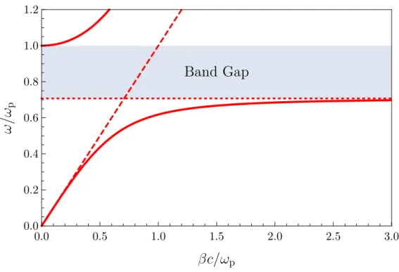
Chapter 2 -Plasmonics 13 0.0 0.5 1.0 1.5 2.0 2.5 3.0 0.0 0.2 0.4 0.6 0.8 1.0 1.2
Figure 2.4: Dispersion of SPPs at the interface between a Drude metal and air (solid line). Also shown are the light line (dashed line), the surface plasmon frequency ωsp (dotted line), and the band gap (shaded region).
which require continuity of Hy and (z)Ez [48]. The well known details are relegated
to Appendix A, where it is shown that SPPs only exist for transverse magnetic (TM) modes, and that for these modes to be confined to the surface we require the dielec-tric function to have an opposite sign in each of the half plane regions. The resulting dispersion equation is β= ω c s M(ω)D M(ω) +D , (2.18)
which is plotted in Figure 2.4 for an interface between a Drude metal and air. Note that we have two distinct modes, each of which is a hybridisation of the original bare light and matter curves. These modes display an ‘anti-crossing’ at the original crossing point, and are separated by an energy gap. The curve that lies outside the light cone corresponds to the SPP mode evanescently confined to the surface withω < ωp, whereas
the curve that lies within the light cone corresponds to the frequency regime ω > ωp
Chapter 2 -Plasmonics 14
mode tends towards the air light curve in the limitβ→0, whereas in the opposite limit
ω tends towards the value
ωsp =
ωp
√
1 +D
, (2.19)
known as the surface plasmon (SP) frequency. At the same time the group velocity tends to zero and the mode develops an electrostatic character, corroborated by the fact that this mode is also a solution of the Laplace equation [49].
Two notable consequences of the SPP dispersion are that firstly, as the lower branch lies outside the light cone, ideal SPPs on smooth surfaces are non-radiative and cannot be directly excited by light [2]. Techniques such as prism [50, 51], grating [52–54] and near-field [55,56] coupling, as well as roughened or patterned metallic surfaces [57] must be used to overcome the momentum mismatch. Secondly, while there is a propagating mode at the interface, perpendicularly to the surface it is of a near-field nature and evanescently confined. This behaviour normal to the interface is characterised by the exponential decay lengthδD= 1/kz =
β2−
M(ω/c)2
−1
, while the propagation has an attenuation length scaleL= [2Im(β)]−1 [58]. Thus we see there is an inherent trade off between localisation and loss.
2.2
Localised surface plasmons
We have begun to see how the manipulation of material properties can drastically alter their electromagnetic response. Ever improving nanofabrication techniques have granted researchers the ability to control system features on a scale less than the wavelength of (visible) light itself, leading to the advent of metamaterials. This class of structures, with subwavelength constituents and patterning, have revealed some remarkable optical properties not found in nature such as electromagnetic invisibility cloaking [8–10], perfect lensing [11, 12] and slow light [13]. In this section we discuss the optical properties of individual metallic nanoparticles, before addressing the collective excitations that emerge in metamaterials consisting of arrays of such constituents in the following section. The interaction of valence electrons with an external radiation source produces a non-propagating excitation in a metallic nanoparticle, termed a localised surface plasmon
Chapter 2 -Plasmonics 15
(LSP). The LSP mode is evanescently confined to the surface of the nanoparticle, with a strong optical field enhancement in this subwavelength region [2,3,49]. This triumph over the diffraction limit has enabled resolution at the molecular level [5]. Such effects are pronounced at the LSP resonance frequency, which for gold and silver nanoparti-cles lies in the visible range, making nanopartinanoparti-cles particularly useful as the functional component in many products and sensors [59]. Moreover, LSPs can be excited by direct light illumination, in contrast to the volume and surface plasmons encountered so far. In this section we will first analyse the eigenmodes of a spherical nanoparticle, as well as the response in presence of a quasistatic external electric field. It will be shown that in this regime, as well as in actuality for nanoparticles with dimensions less than 100nm under visible light illumination, the dominant mode is a dipolar excitation at the LSP resonance frequency. We then present an account of the effects of size, shape, material and dielectric environment on the LSP resonance. Following this we introduce an effective Hamiltonian, starting from the full electronic description and performing a decomposition into electronic centre of mass coordinates. This will form the noninter-acting term of the Hamiltonians in subsequent chapters. Finally we discuss damping mechanisms for LSPs.
2.2.1 Eigenmodes of a spherical nanoparticle
We consider a metallic nanosphere of radius n embedded in a dielectric medium D as
shown in Figure2.5. Thus the full system can be described by the dielectric function
(ω, r) = M(ω) , r <n D , r≥n . (2.20)
In the absence of external charges and fields, the electric potential eigenmodes are the well known solutions of the Laplace equation [49]
Φl(r, θ) = Al(r/n)lPl(cosθ) , r <n Bl(n/r)l+1Pl(cosθ) , r≥n , (2.21)
Chapter 2 -Plasmonics 16
n
Figure 2.5: Schematic of a nanosphere of radius n embedded in a medium with dielectric constantD.
where Pl is a Legendre polynomial of order l, θ is the polar angle from the z-axis, Al
and Bl are coefficients which require additional boundary conditions to specify, and
unphysical solutions at r → 0 and r → ∞ have been neglected. Of course due to the spherical symmetry there are additional solutions for each choice of theˆz direction. Continuity of the tangential electric fieldEθ=−(1/r)(∂Φl/∂θ) is automatically satisfied
whereas continuity of the normal component of the displacement fieldDr =−(∂Φl/∂r)
designates the constraint
lM(ωl) + (l+ 1)D= 0, (2.22)
which for a Drude metal leads directly to the LSP eigenfrequencies
ωl =ωp
s
l l+ (l+ 1)D
, (2.23)
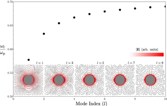
where ωM ≡ ω1 is the Mie frequency [6]. It is seen in Figure 2.6 that as l increases
the mode becomes increasingly confined to the nanosphere surface, and the multipole solutions gradually approach the SP frequency ωsp of a bulk metal-dielectric interface.
However, the l= 1 solution is the only mode with a non-zero total dipole moment and thus the only mode that can couple to external radiation [49], in the limit of vanishing particle size with respect to the wavelength λ. Indeed for particles with radii up to tens of nanometers at visible wavelengths the optical response is strongly dominated by this l= 1 dipolar mode [6, 60]. Thus for n λwe can consider the effect of external
radiation in the quasistatic limit, by considering a spatially homogeneous electric field
Chapter 2 -Plasmonics 17
Figure 2.6: The eigenfrequency of the lth LSP mode of a nanoparticle in air (dots) is seen to tend towards the bulk SP frequencyωsp≈0.71. The insets show the electric field lines of various modes (given in each inset), as well as a visualisation of the field strength (color scale in arbitrary units).
boundary condition limr→∞(Φ) =−E0zto the total electric potential Φ =PlΦl, which
gives the total electric fieldE=−∇Φ as
E= 3D M+ 2D E0 , r <n E0+ 3ˆr(ˆr·p)−p 4π0Dr3 , r≥n . (2.24)
Knowledge of the electric field eigenmodes of a nanosphere is useful for the development of interaction models used in later chapters. However, we must be wary of the realms of applicability of a quasistatic approximation and neglecting higher order multipoles. We will shortly collate studies on the effects of size, shape and material composition on the optical response of metallic nanoparticles.
2.2.2 Electronic centre-of-mass decomposition
We now seek to obtain an effective Hamiltonian for an individual spherical nanoparticle starting from a microscopic description. Although one can write down the exact Hamil-tonian in terms of an ensemble of interacting ions and electrons, it is an impossible task to solve the corresponding Schr¨odinger equation and thus approximation schemes are
Chapter 2 -Plasmonics 18
employed. The jellium model [61], whereby the complicated ionic structure is replaced by a constant background charge, has been used successfully to describe the properties of metallic nanoparticles [62–64], modelling the ionic background as a jellium sphere with sharp boundaries and a radiusn. By a trivial application of Gauss’s law in integral
form one finds the single-particle confining potential of valence electrons to be
U(r) = N e 2 8π0Dn3 (r2−3n2)Θ(n−r)− N e 2 4π0Dr Θ(r−n), (2.25)
where Θ is the Heaviside step function and N is the total number of valence electrons. Thus the Hamiltonian for the N valence electrons is
H= N X i p2i 2m+U(ri) + e2 8π0 N X j6=i 1 |ri−rj| . (2.26)
One can express this Hamiltonian in terms of the electronic centre of massh=P
iri/N,
its conjugated momentum Π=P
ipi and the relative coordinates in this frame: r0i = ri −h and p0i = pi −Π/N. Assuming the displacement of the centre of mass h is small compared to the nanoparticle size, the single-particle potentialU(|r0i+h|) can be expanded around |h|= 0. Keeping terms up to second order in h within the harmonic part of the potential (r0 < n), and up to first order in the coulombic tail (r0 ≥ n)
transforms the Hamiltonian to
H =Hc.m.+Hrel+Hc. (2.27)
The Hamiltonian of the centre-of-mass coordinates is
Hc.m= Π2 2M + 1 2M ω 2 0h2, (2.28)
where M = N m is the total mass of the valence electrons and ω0 =ωM
p
1−Nout/N
is the Mie frequency ωM renormalised by a factor dependent on the number of valence
electrons outside the jellium sphere, Nout = N −PNi=1Θ(n−ri). Hrel is simply the
Chapter 2 -Plasmonics 19
the transformation (p,r) →(p0,r0). The coupling between the two coordinate systems to first order in h is given byHc and is
Hc=meωM2 N X i r0i·h ( Θ(n−ri0) + n3 r0i3Θ(r 0 i−n) ) . (2.29)
This approximation scheme allows us to treat the localised surface plasmon as the oscil-lation of a collective coordinate associated with the centre of mass motion, damped by interactions with the relative-coordinate system.
As has been established by multiple photoabsorption experiments [65] the spectra of metallic nanoparticles typically display a ‘giant dipole resonance’ close to the classical Mie values for the dipole resonance frequency of a classical small metal sphere. Thus this resonance should be interpreted as being due to the collective motion of the delo-calised valence electrons, with the external electromagnetic field coupling directly with the electronic centre-of-mass. In this way Hc.m., which is formally equivalent to the
Hamiltonian of a point dipole, is the dominant term in the Hamiltonian for an LSP.
2.2.3 Effects of size, shape and material
Clearly the optical properties of nanoparticles depends on the dielectric environment, as seen explicitly in equation 2.23, as well as the material constituent of the nanoparticle via the plasma frequency. The effect of temperature on the absorption spectra is minimal for commercial electronics operating ranges [66,67], as seen in Figure 2.7. However, it is the geometry of nanoparticles that is of interest, as one can fine tune the plasmonic properties by manipulating the size and shape of nanoparticles [60].
There are a wide range of nanofabrication techniques with varying levels of resolution and throughput [68]. With electron beam lithography it is possible to achieve sub-nanometer resolutions [69,70], whilst few nanometer resolution is readily realisable [71]. There are a host of other methods such as the chemical synthesis of nanoparticles, including the use of DNA as a template to organise few nanometre nanoparticles into single chains with long-range order [72]. Consequently it is possible to precisely engineer the size, shape and arrangement of nanoparticles and thus the optical response.
Chapter 2 -Plasmonics 20
Figure 2.7: Temperature dependence of the absorption spectra for gold nanoparticles with radii of 22nm. The absorption spectra are measured at 18◦C (solid line) and 72◦C (dashed line) using spectrophotometry. Reprinted with permission from [66]. Copyright 1999 American Chemical Society.
Equation 2.23 suggests that the resonance frequency of metallic nanoparticles is size independent, however, spectroscopy measurements show that in reality this is not true. Whilst reports on the governing relationship between the size of nanoparticles and their spectra can be in conflict [73], as this scaling is dependent on other parameters of the particle and environment, in general an increase in particle size corresponds to a red-shift of the resonance peak [74], as seen in Figure 2.8. We can intuitively understand this shift as due to an increase in the separation of oppositely charged surfaces either side of the nanoparticle as its size increases, leading to a reduction in the restoring force and hence a decrease in the resonant frequency.
As well as the resonance peak, the width of the optical spectrum is also size-dependent, with two key mechanisms. Nanoparticles on the scale of ten nanometres have dimensions comparable to or less than the electron mean free path, leading to a modified scattering rate of the dielectric function2.12due to collisions with the nanoparticle surface, leading to a 1/nbroadening ofγ as the particle size decreases. On the other hand as the particle
size increases radiation damping, which scales like n3, also causes a significant
broad-ening. Accounting for these two key contributions, one typically models the scattering rate as [75]
Chapter 2 -Plasmonics 21
Figure 2.8: Plot of the peak plasmon resonance wavelength of individual nanoparticles as a function of their size, for three different shapes. Here size refers to: the diameter of spheres, the length between opposite corners of pentagons, and the length of a side of triangles. In each case there is a red-shift with increasing size, as well as a clear dependence on the shape itself. Reprinted from [74], with the permission of AIP Publishing.
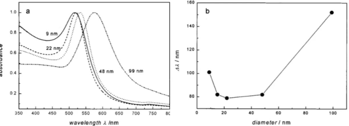
Figure 2.9: (a) Optical absorption spectra of spherical gold nanoparticles, normalised to the spectral peak maximum, for various diameters. (b) The bandwidth ∆λof the spectra (full-width-half-maximum when fitted with a Lorentzian curve). Reprinted with permission from [66]. Copyright 1999 American Chemical Society.
γ =γ0+
AvF n +
2ω4Mn3
3c3 , (2.30)
where γ0 is the Ohmic damping rate, vF is the Fermi velocity of conduction electrons
and A is a geometrical factor [66, 76]. Thus for each nanoparticle and environment there is a dimensional sweet spot where the total broadening effects are minimal. In the example of Figure2.9with gold nanoparticles we can see this occurs at aboutn= 10nm.
Chapter 2 -Plasmonics 22
Figure 2.10: From left to right we see a 30nm thick nanoparticle rod, disk and two triangles, in scanning electron micrographs (top), field images (middle), and dark-field spectra (bottom). The white scale bar is 300nm. Reprinted with permission from [77]. Copyright 2007 John Wiley & Sons.
The shape of a nanoparticle is also a key parameter in determining the optical response. In Figure 2.8 we see that the spectral peaks of different shapes are well separated in frequency. This effect is visually evident in Figure2.10where different shaped nanopar-ticles appear different colours in dark-field microscopy [77]. We also see that there are additional types of resonances in differently shaped nanoparticles. The nanorod has two discernible dipole resonances associated with the major and minor axis, which are red and blue shifted respectively. The triangular nanoparticles also display two resonances, in this case these correspond to a dominant dipole mode and a quadrupole mode at a smaller wavelength [78].
The multipolar characteristics of nanoparticles are pertinent to the reliability of mod-els used throughout this thesis, which consider only the dipole response. Typically for nanospheres and similar geometries on the scale of a few tens of nanometers the electro-magnetic response is overwhelmingly dipolar in nature [79,80]. Even as the quadrupole mode becomes appreciable in nanoparticles on the scale of several tens of nanometres,
Chapter 2 -Plasmonics 23
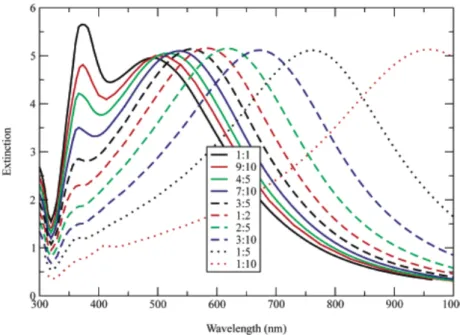
Figure 2.11: Exact electrodynamic calculation of the extinction spectra of oblate spheroids, all with the same equivalent volume, corresponding to a sphere radius of 80nm. In this figure the extinction is normalized to the area of a circle with radius equal to the semi-major axis. As the asymmetry is increased the dipole peak is red-shifted while the quadrupole mode shrinks in intensity. Reprinted with permission from [60]. Copyright 2003 American Chemical Society.
the dipolar mode is typically still dominant and well separated in frequency. Moreover, it is possible to introduce an asymmetry into the geometry so as to quench the quadrupole mode [60] as shown in Figure2.11.
2.2.4 Damping mechanisms
The dephasing time T2 = 2~/Γ of an LSP can be extracted from the homogeneous
linewidth Γ [3]. Attempts to deduce the linewidth of single nanoparticles from measure-ments on aggregates are limited by the inhomogeneous broadening introduced by sample variation and thus it can be preferable to conduct near-field measurements of individual nanoparticles [4]. Typical values for the dephasing time lie in the range 5fs≤T2 ≤10fs
[3] with various radiative and non-radiative decay mechanisms.
We have seen in Figure2.9that radiative damping becomes dominant for larger nanopar-ticles as the particle volume increases, whilst the contribution to Γ is quite minimal for nanoparticles on the order of ten nanometres [81]. Instead the decay of plasmons into interband and intraband excitations introduces a significant dephasing factor [82]. Ad-ditionally for such small particles the electron mean free path becomes comparable to
Chapter 2 -Plasmonics 24
the nanoparticles dimensions and surface scattering introduces the characteristic 1/n
dependent broadening to the linewidth [73] as discussed previously.
For very small nanoparticles on the order of single or few nanometers Landau damping causes a significant linewidth broadening [6, 62, 63]. This effect can be understood in the context of section 2.2.2 where the Coulomb tail of the confining potential of a nanoparticle leads to a couplingHc between the centre of massHc.m.and the electronic
bathHrel, inducing the decay of excitations of the centre-of-mass oscillation into
particle-hole pairs in the electronic environment.
We have seen that the resonance peaks are strongly dependent on nanoparticle shape and this is equally true for damping timescales. For example, S¨onnichsen et al. achieved a drastic reduction of the dephasing rate in gold nanorods [83] in contrast to nanospheres. In gold nanoparticles interband excitations become significant above a threshold of 1.8eV, so by increasing the aspect ratio of nanorods one redshifts the LSP resonance such that these effects are suppressed. This is in contrast to nanospheres where such a redshift can only be produced geometrically by an increase in volume, accompanied by an increase in radiative damping that negates any decrease to Γ.
2.3
Arrays of metallic nanoparticles
Dephasing times, as well as the majority of other optical properties are of course modified in the case of interactions between two or more nanoparticles. Now that we have deliv-ered a basic description of the optical properties of individual nanoparticles we proceed to discuss the behaviour of collective excitations in arrays of interacting nanoparticles. We will see that interactions give rise to extended plasmonic modes with optical proper-ties that are tunable not just by the individual constituents but by the lattice structure of the metamaterial and the microscopic interactions between LSPs. Understanding these modes is essential as they are the channel guiding electromagnetic radiation with strong lateral confinement over macroscopic distances.
In fact a significant deviation from the response of a single nanoparticle is seen for even just an interacting pair, where the plasmon resonance peak exhibits a red (blue) shift for polarisation parallel (perpendicular) to the separation axis [84]. One can visualise this
Chapter 2 -Plasmonics 25
Figure 2.12: There are two sets of parallel and anti-parallel eigenmodes for an in-teracting nanoparticle dimer, those that are orientated perpendicular (transverse) and parallel (longitudinal) to the separation axis. Those with a net dipole moment are called bright modes, whereas the dark modes have no net dipole moment. The interac-tion also red or blue shifts the resonant frequency with respect to two non-interacting dipoles, as indicated by the colour of the enclosing boxes.
effect as shown in Figure2.12, where the parallel polarisation is energetically favourable for the bright mode of two dipoles interacting quasi-statically.
In reality this situation is more complicated, with a competition between static, radiative and retardation effects. For an array of nanoparticles of radii n and lattice constant a excited by external radiation with wavelength λ n the optical response can be
calculated in the Coupled Dipole (CD) approximation [17,85]. This consists of obtaining a self consistent solution to the response of each particle at location Ri with dipole polarisation pi =αE(Ri) in the presence of the fields of the otherN −1 particles [17, 85,86]: E(Ri) = 1 4π0D N −1 X j6=i Sij (2.31)
Chapter 2 -Plasmonics 26 where Sij = eikrij | {z } retardation ( k2ˆr ij×(ˆrij×pj) rij | {z } radiative +[1−ikrij] electrostatic z }| { [3ˆrij(ˆrij ·pj)−pj] r3 ij | {z } short-range ) , (2.32)
k = 2π/λ, and rij denotes the interparticle separation vector between the ith and
jth particle in an array. Good agreement between the CD approximation and more sophisticated electrodynamic calculations that include several multipoles is found for nanoparticles with a radius of 30nm and less [17], as well as for complementary exper-imental results [86]. We see that equation 2.32 captures short-range and electrostatic dipolar interactions (1/rij3 terms), radiative dipolar coupling (1/rij terms) as well as the
effects of retardation (the factor eikr). In Figure 2.13 we see the shift in the resonant frequency of the coupled array with decreasing lattice spacing, which blue shifts for the larger spacings where (retarded) radiative interactions are dominant, but red shifts for the smaller spacings where electrostatic interactions are dominant. Such long-range electrodynamic interactions only begin to become important for spacings greater than
λ/2π [17,86] (i.e. a &70nm for visible frequencies), thus for closely packed arrays we can approximate equation2.32 in the limitaλas
E(Ri) = N0 X j6=i 1 4π0Drij3 [3ˆrij(ˆrij ·pj)−pj], (2.33)
whereN0 signifies a truncated sum up to terms wherekr
ij 1 holds. We note that for
this approximation to hold we also require a minimal separation so that the nanoparticles experience a dipolar field from neighbouring particles, rather than the more complicated fields that exist close to the particle surface. Exact quasistatic calculations of linear chains of spherical nanoparticles have quantified this minimal separation to be n.a/3
[18]. The effects of retardation would cause the single band of the quasistatic dispersion to split into two anticrossing bands, as well as effecting the phases of each individual nanoparticle and thereby the distribution of constructive and destructive interference in the array. Whereas radiation losses results in a complex dispersion relation.
In modelling these electrostatic dipolar interactions one only needs to account for a few nearest neighbours to capture the important optical properties of arrays. For example,
Chapter 2 -Plasmonics 27
Figure 2.13: The peak resonant wavelength λmax of an array of nanoparticles, cal-culated in the Coupled Dipole approximation, for various lattice spacings a. For de-creasingawe see first a blue-shift for larger spacings where long-range electrodynamic interactions are the dominant contribution to the optical response. However, there is a turning point at about 300nm, below which there is a red-shift characteristic of electrostatic dipolar interactions. The calculations were performed for oblate spheroids with a principal axis of length 40nm and eccentricity 0.98, for hexagonal silver (black crosses), square silver (blue diamonds), hexagonal gold (green circles), and square silver (red squares) arrays. Adapted with permission from [86]. Copyright 2003 American Chemical Society.
measurements of closely spaced nanoparticle chains show a squeezing of the optical field with respect to a single nanoparticle, concentrated in interstitial sites [14]. As seen for two nanoparticles there is an energy split between parallel and perpendicular modes, which asymptotes with increasing chain length for only a few nanoparticles [16], as seen in Figure 2.14. In fact in section 4.2.7 we show that the qualitative features of the bandstructure and eigenstates of a honeycomb array are captured by considering only nearest-neighbour interactions. Thus remembering equation2.28for the Hamiltonian of an isolated nanoparticle, and referring to equation2.33we can see that the Hamiltonian of the near-field dipolar interactions between an array of metallic nanoparticles is
H =H0+Hint, (2.34)
Chapter 2 -Plasmonics 28
Figure 2.14: (a) Collective plasmon resonance energies for both longitudinal (EL) and transverse (ET) excitations for Au nanoparticle arrays of different lengths obtained via far-field spectroscopy (red circles) and FDTD simulations (black stars). (b) Simulation results for the collective plasmon resonance energies for transverse excitation of Au spheroids with aspect ratios 3:1 (blue diamonds). The resonances asymptote after only a few nanoparticles. Reprinted with permission from [16]. Copyright 2002 AIP Publishing LLC. H0 = X R Π2(R) 2M + 1 2M ω 2 0h2(R) , Hint= N2e2 4π0D X R X j Cj, (2.35)
and Cj = 1−3(ˆp·ˆej)2 wheree denotes the nearest jth nearest-neighbour vector. Here
we have made the implicit assumption that all the dipoles are polarised in the same direction ˆp, which is valid in the electrostatic limit as we discuss further in section 4.1
and appendix B.
So far we have discussed the collective plasmonic modes in arrays of metallic nanopar-ticles. In chapter 5 we will investigate their interaction with the photonic modes of a cavity, giving rise to new coupled light-matter modes termed plasmon polaritons which are the true eigenmodes responsible for transporting radiation. For this reason we now provide an introduction to the strong light-matter coupling regime and polaritons in general.
Chapter 2 -Plasmonics 29
2.4
Polaritons
As has been evidenced throughout this chapter, it is the dielectric function of a material which performs the leading role in determining the optical response; and we have seen that we can significantly alter the properties of collective plasmons by tailoring the material environment. In reality these plasmonic modes do not exist in isolation, but interact with their photonic environment. Thus we can change the properties of plasmons through manipulation of the photon field.
In the so-called weak coupling regime between light and matter one treats the radiation field as a perturbation on the dynamics of the matter system, with the semiclassical theory of radiation providing an adequate description of the optical properties [87]. In this regime perhaps the most well-known example is the Purcell effect [88], whereby the spontaneous emission rate of an atom in a cavity is enhanced if the transition energy is in resonance with the cavity mode. On the other hand, if the interaction rate between light and matter excitations is faster than average dissipation rates, the perturbative weak coupling regime breaks down and one must describe interactions in the strong coupling regime.
The weak coupling regime has been extensively explored in metallic nanoparticle arrays [14–16, 18, 34]. However, it has long been known that the fundamental absorption processes in periodic systems require a full quantum-field-theoretic treatment of the strong-coupling regime [35, 36] which takes into account the conservation of crystal momentum between the photonic and matter excitations. The true eigenmodes are a coherent superposition of plasmons and photons, termed plasmon polaritons [89]. We briefly review the seminal work by Hopfield who, as well as Fano, first treated the strong coupling regime in the context of excitons in bulk solids. The applicability of this theoretical methodology to plasmonic systems is a key component of our own work in later chapters.
2.4.1 Hopfield and the strong coupling regime
In 1958 Hopfield published a treatment of the excitonic contribution to the dielectric function of an insulating crystal [35], showing that the interaction of photons and exci-tons leads to the formation of a hybrid mode. Termed a polariton, it is neither solely
Chapter 2 -Plasmonics 30
photonic or excitonic in nature, but a coherent superposition of the two.
To elucidate the inadequacies of the semiclassical description consider a 3D array of identical atoms, each with a ground state φR and excited state ψR, where R are the
atomic positions. The elementary excitations of the crystal ΨR =ψRQR06=RφR0 with
just one atom at R in an excited state don’t have the required translational symme-try, but can be used to construct a Bloch state which is the zero-order excited state wavefunction Ψk= 1 √ N X R eik·RΨR, (2.36)
where N is the total number of atoms. Thus transitions to the ground state are pro-portional to the factorP
Rexp[i(k−k0)·R] with emission of a photon with wavevector k0. In the absence of Umklapp processes this dictates the conservation rule k=k0, so that each exciton is coupled to just one radiation mode. Due to the lack of a density of final states real transitions are forbidden, and instead energy is continuously exchanged between the excitonic and photonic modes. This suggests that we cannot think of ab-sorption in a dielectric as simply a scattering process whereby a photon is absorbed by an exciton and subsequently re-emitted in an arbitrary direction, as would be the case for an isolated atom. Instead, the energy of an illuminating source is stored in these coherent hybrid modes of the crystal, and thus we require a description of the true eigenmodes of the light-matter interaction Hamiltonian of the crystal.
Excitons can be treated as approximate bosons in the limit nexca30 1, where nexc is
the density of excitons and a0 is the Bohr radius [87]. In this case the full electronic
Hamiltonian can be decomposed into a part that is quadratic in exciton creation and annihilation operators, formally mapping to a quantised polarisation field, plus higher order terms which can be treated as a perturbation [35]. We are not interested in excitons per se, so to elucidate the formalism applied to light-matter interactions in the strong coupling regime, let us consider the simpler and more general problem of quantising a polarisation field in interaction with the electromagnetic field. The Lagrangian density for this system is
Chapter 2 -Plasmonics 31 L= 1 8π(E 2−c2B2) | {z } light + 1 2ω02β( ˙P 2−ω2 0P2) | {z } matter + (A·P˙ +U∇ ·P) | {z } interaction , (2.37)
whereω0 is the natural frequency of the polarisation field andU is the electromagnetic
scalar potential. This Lagrangian describes the usual Maxwell equations plus an oscil-lating polarisation density with constitutive equation ω−02P¨ +P=βE . We can switch to the Hamiltonian representation and expand in terms of the Fourier components of the fields A and P and their conjugate momenta. These fields represent a system of harmonic oscillators and so we introduce standard bosonic creation and annihilation op-erators that diagonalise the decoupled light and matter terms, expressing the interaction part in these operators also. We find the full Hamiltonian to be
H =~ X q ωqphc†qcq | {z } light +ω0a†qaq | {z } matter +Hint, (2.38)
wherea†qandc†qcreate quanta of the matter and light fields respectively,ωphq =c|q|and
the field operators in terms of the creation operators are
A=X q 2πc~ V|q| 1/2 cqeiq·R+c†qe−iq·R , (2.39) P=X q ~ω0β 2V 1/2 aqeiq·R+aq†e−iq·R, (2.40)
whereV is the quantisation volume (which is compensated by the sum over all R). The interaction Hamiltonian is Hint=~ω0 X q h iξq c†qaq+c−qaq+ξq2c†qcq+c−qcqi+ H.c., (2.41) where ξq = q
πω0β/ωqph parametrises the interaction strength. Note that we have
suppressed the index representing the different possible polarisations. The Hamiltonian has translational invariance and different polarisations are decoupled so it is sufficient to choose a single polarisation. The eigenmodes of this coupled system, termed polaritons,
Chapter 2 -Plasmonics 32
are a coherent superposition of light and matter excitations. Thus we introduce the operator
γq=waq+xcq+ya†−q+zc†−q, (2.42)
which, if it is to be a normal-mode annihilation operator must obey the Heisenberg equation
γq, H=~ωpoq γq, (2.43)
where ωqpo is the eigenfrequency dispersion of the polaritons. The eigenvalue equation 2.43 can be written in matrix form as
ωqph/ω0+ 2ξ2q −iξq −2ξ2q −iξq iξq 1 −iξq 0 2ξq2 −iξq −ωqph/ω0−2ξq2 −iξq −iξq 0 iξq −1 w x y z = ω po q ω0 w x y z , (2.44)
which leads to the polaritonic dispersion
ωpoq = √1 2 Wq2± q W4 q−4(ω0ωphq )2 1/2 , (2.45) where Wq2 =ω02+ (ωqph)2+ 4ω0ωqphξ2q, (2.46)
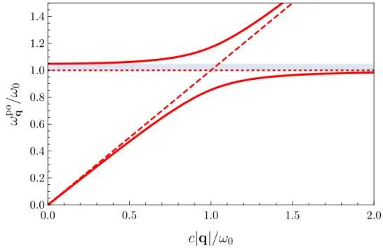
as shown in Figure 2.15. We see the prototypical polaritonic splitting and asymptotic tendency to bare light and matter curves and a band gap proportional to β. Note that in the polaritonic dispersion 2.45 we neglected the two negative energy solutions from the eigenvalue equation 2.44 as unphysical. We will continue to ignore such solutions for the rest of the thesis.
Chapter 2 -Plasmonics 33 0.0 0.5 1.0 1.5 2.0 0.0 0.2 0.4 0.6 0.8 1.0 1.2 1.4
Figure 2.15: The polaritonic dispersion in an infinite dielectric medium (solid lines). Also shown are the light line (dashed line) and the resonant frequency of the polarisation field (dotted line). The shaded region corresponds to the band gap induced by the anti-crossing. In the figure 4πβ= 0.1.
2.5
Chapter Summary
The diffraction limit is a serious impediment to the resolution of microscopic structures. However, we have seen that metallic nanoparticles enable us to overcome this limit, as the electromagnetic fields associated to LSPs in nanoparticles are evanescently confined to the surface and significantly enhanced within subwavelength regions. LSP resonances can be excited by direct light illumination and typically lie in the visible spectrum. The exact frequency and bandwidth can be modulated by the size, shape, material and environment of the nanoparticle.
The situation becomes yet more interesting when we consider interactions between LSPs in arrays of nanoparticles, as this leads to new collective propagating plasmonic modes, the properties of which depend on the underlying lattice structure. Such metamaterials can exhibit a variety of novel optical phenomena not found in nature, such as electro-magnetic invisibility cloaking, perfect lensing and slow light [8–13]. In the next section we will unveil some of the fascinating properties of graphene, which in combination with this section will explain our motivation in researching the plasmonic properties of a honeycomb array of metallic nanoparticles.