2017 International Conference on Electronic and Information Technology (ICEIT 2017) ISBN: 978-1-60595-526-1
An Effective Solution Based on Genetic Algorithm for Virtual
Network Functions Placement
Xin-gang WANG
Administration Center for the DTH Service in China, SAPPRFT, Beijing, 100045, China
*Corresponding author
Keywords: Network function virtualization (NFV), Service function chain (SFC), Virtual network function (VNF), VNF placement, Genetic algorithm.
Abstract. Network functions virtualization (NFV) is a new design paradigm for network architecture. It is a potential technology to solve the current issues that the traditional networks face, such as excessive expenditure, complex configuration and waste of resources. NFV can decouple the network functions from physical dedicated hardware and virtualized them as software. Therefore, these virtualized functions, called as virtual network functions (VNF), can be managed flexibly in a cost-effective way. One of the most interesting topics is how to place VNFs in physical networks efficiently. In this work, we investigated this VNF placement problem and explained it in detail. Then we proposed an effective solution based on the genetic algorithm (GA) to cope with it. In order to obtain the expected economic benefits when processing service function chains (SFC), the objective of our solution is minimizing the number of VNF instances implemented. This objective can also help prevent over-provisioning or under-provisioning and achieve reasonable physical resource allocation. The simulation results show that the proposed solution has a good performance in resources utilization. It can process SFC requests effectively by instantiating not too many VNF instances. The delay of the end-to-end service delivery is also controllable when searching for the optimal solution.
Introduction
Middleboxes are responsible to support various network functions in today's networks. They play important roles in many aspects, such as security functions (e.g. firewalls, IDS), forwarding functions (e.g. routers, NAT), and performance optimization (e.g. caching, network proxy). However, as networks continue to expand, customers demand for diverse network services and high-speed data transmission. Traditional network operators have to buy more middleboxes to provide new services. Recent study has shown that the number of middleboxes is already close to the number of routers in enterprise networks (including data centers and Internet service providers’ (ISP) networks) [1]. The infrastructure becomes more difficult to reconfigure and is hard to manage efficiently for the explosive growth of the number of physical devices. Furthermore, due to the dependence on physical network topology and other constraints, operators confront lots of unexpected deterioration in network environment, such as waste of resources and high operational expenditure (OPEX). These problems limit the development and innovation of networks.
dilemma of network’s development. In NFV architecture, researchers can decouple the network functions from dedicated physical equipment and immigrate them to commercial standard hardware [2]. Then these virtual network functions (VNF) can be placed in physical networks dynamically. It is potential to promote the speed, flexibility and scalability of networks in the future. ISP will have the capability to orchestrate network services and process them with high availability and timeliness on demand. Customers no longer need to buy many physical devices to implement their service requests in this scenario.
People believe that NFV technology will definitely facilitate the networks’ performance greatly. However, the traditional default scheme to place VNF may lead to significant waste of physical resources. In order to improve the resources utilization and achieve the expected economic benefits, an efficient algorithm to place VNFs in physical networks should be proposed. Then, operators can instantiate less VNF instances to accept and process SFC to reduce the extra capital expenditure (CAPEX) and OPEX. Therefore, in this work, we investigate this VNF placement problem and explain it in detail. We divide this problem into three concrete steps. Our main contribution is proposing an effective solution based on the genetic algorithm (GA) to deal with it. The objective is to minimize the number of VNF instances implemented while the system is still able to handle service function chain (SFC) requests well. We also set a secondary objective: Maintain the end-to-end delay controllable. The two objectives make our effort have great practical significance, because it not only ensures the reasonable allocation of physical resources, but also achieves load balance.
The rest of this paper is organized in the following: Section II introduces the related work, including the current researches in NFV and the related solutions about this problem. Section III describes the network model in detail and formulizes this VNF placement problem. Section IV briefly demonstrates the idea of genetic algorithm, and formally proposes our solution based on it. Section V shows the simulation results and the evaluation. Section IV shows the conclusion and a simple summary.
Related Work
Researchers in domestic and foreign institutions both are making unremitting efforts to promote the development of NFV. The NFV Technology Study Group in European Telecommunications Standards Institute (ETSI) has cooperated with network operators and equipment suppliers to define the related standard of VNFs, including their types, some use cases and architecture [3]. Based on that work, authors in [4] made a survey of the state-of-the-art in NFV, aiming to identify promising research directions in this area. They proposed many related and interesting problems in NFV architecture.
of VNF instances as well as high resource utilization. However, there are few relevant studies on the problem of VNF placement using GA for the objective of minimizing VNF instances.
Problem Formulization
Overview of the Problem
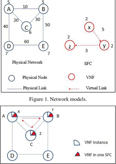
[image:3.612.204.407.292.577.2]It can be seen from Fig. 1 that SFC is made up of several interconnected VNFs (e.g. firewalls, intrusion detection systems, load balancers). Each VNF should be instantiated at the specific locations in physical network according to certain rules. Different SFCs can share the same VNF instance implemented at the physical node. Therefore, this VNF placement problem consists of three steps: Firstly, choose the appropriate locations in a physical network to implement the different VNFs; secondly, allocate physical resources for VNFs; thirdly, form a continuous end-to-end data path among these VNF instances so that traffic can pass through them orderly. The solution should also make sure that the end-to-end delay is controllable, which includes the processing delay of each function and the forwarding delay between two VNFs.
Figure 1. Network models.
Figure 2. Resource allocation for VNF placement.
Network Models
The network topology of our NFV infrastructure is composed by physical nodes and links, shown in Fig. 1. It is represented by an undirected graph G= (N, L) where N is
the set of nodes and L is the set of links. We use P to denote physical resource. Each
physical node i (i∈N) has some computational resource Ci P
(the number near the physical node) so that any types of VNF can be processed at it. The links between two nodes have some bandwidth resource Bi,j
P
(the number near the physical link) with the forwarding delay Di,j
P
,(i,j∈N). The physical nodes indicate the specific locations
network, and it is represented by a directed graph S=(F,E) where F is the set of VNFs, F:{f,f2...fi}, and E is the set of virtual links, showed in Fig. 1 as well.
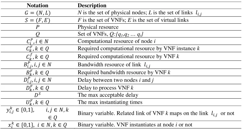
[image:4.612.110.503.139.349.2]These notations as well as the variables are revealed in Table 1, and their meanings will be explained in an example below.
Table 1. Annotation and description.
Notation Description
= (, ) N is the set of physical nodes; L is the set of links ,
= (, ) F is the set of VNFs; E is the set of virtual links
P Physical resource
Q Set of VNFs, Q:{q1,q2 … qi}
, ∈ Computational resource of node i
, ∈ Required computational resource by VNF instance k
, ∈ Required computational resource by VNF k
,, , ∈ Bandwidth resource of link ,
, ∈ Required bandwidth resource by VNF k
,, , ∈ Delay between two nodes i and j
, ∈ Delay to process VNF k
The max acceptable delay
, ∈ The max instantiating times
, ∈ 0,1 , , ∈ ,
∈ Binary variable. Related link of VNF k maps on the link , or not !∈ 0,1 , ∈ , ∈ Binary variable. VNF instantiates at node i or not
Generally speaking, a virtual network node can be seen as a package with a host or other software, such as a virtual machine (VM) on an operating system [4]. In NFV architecture, virtual nodes are VNFs connected by virtual links. We distinguish the “VNF instance” and “VNF” in this paper. The types of VNF instances or VNFs are both included in the SFC set Q. When a VNF intends to be instantiated at one physical
node, it will either generate a new VNF instance or consume the remaining computational resource of an existing instance of the same type. If a VNF k
has to generate a new VNF instance, it will require a certain computational resource
Ck F
(a quarter of the circle in Fig. 2) to implement this instantiation. While the VNF just requires a certain proportion of computational resource in VNF instance, called
Ck f
(one eighth of the circle in Fig. 2), for processing, and the rest of it is ready to process the upcoming same type of VNF. Each node will spend a certain delay Dk
F
to process VNF k.
While the SFC’s virtual link in set E is the logical connection between two virtual
nodes. They are dynamically established on demand. In this paper, we only process SFC in the form of linear. So we distinguish a virtual link by its egress node, namely
ef, e∈ E, f∈ F. The required bandwidth resource is denoted by Bk F
. There is an important thing to stress that each type of VNF can be instantiated at most Uk
F
times. This number is decided by their service providers.
The details of a simple example to place VNFs in physical network are shown in Fig. 2. This figure mainly demonstrates a view of resources allocation and utilization at physical nodes. The SFC with VNF x, VNF y and VNF z is placed at the physical
nodes A, B and C, respectively. Each VNF firstly implement their related instance and
require their proportion of computational resource for processing.
computational resource for the following SFCs when a VNF instance or VNF end its lifecycle. It ensures that customers will not occupy the resources permanently and the infrastructure can be shared in a high efficient way. Obviously, even if the above provisions improve the resources utilization, the number of VNF instances will still continue to go up as the SFC requests increase. Consequently, it is important to obtain an efficient solution to place VNFs to minimize the number of VNF instances.
Problem Formulation
In this section, we formally formulize this VNF placement problem as an Integer Linear Program (ILP). The objective is seeking for the minimum number of VNF instances implemented. It is based on the fact that the result has direct significant impact on the cost to process SFCs for the network operators. Implement one VNF instance will require much computational resources, so the fewer VNF instances are implemented, the less expenditure operators will spend.
Objective:
"# ∑ ∈%∑∈!, ∈ , ∈ (1)
The binary value xi k
= {1, 0} denotes whether VNF instance k is placed at the node i
or not.
We take series of constraints into account when searching for a reasonable path with the optional nodes to implement VNF, such as the requirements of computational resource and bandwidth resource, and delays as well. Constraints are stated in the following:
∑∈! ∙ (()) ≤ , ∈ , () ∈ (2)
Constraint (2) ensures that the sum of the computational resources required by the VNF instances at each physical node i should not exceed the resources the node i has.
∑∈!∙
(()) ≤ ∑∈!∙ (()) , ∈ , , ∈ , () ∈ (3)
Constraint (3) ensures that the remaining computational resources of VNF instances at a certain physical node should be greater than the resource that the upcoming VNFs will require.
∑∈ , ∙ (()) ≤ ,, , ∈ , ∈ , ()∈ (4)
Constraint (4) ensures that the required bandwidth resource should not be greater than the bandwidth resource that the certain physical link has. The binary value
yi,j k
={0,1} denotes the virtual link is mapped on physical link li,j or not.
∑ ∈%! = 1, , ∈ (5)
Constraint (5) ensures each VNF can be placed at a physical node for only once.
∑∈! ≤ 1 , ∈ (6)
Constraint (6) ensures a physical node should implement at most one VNF from the same SFC.
∑∈ , ∙ ,(()) + ∑∈(()) ≤ , , ∈ , ∈ , ()∈ (7)
Constraint (7) ensures that the total processing delay should not be greater than the highest acceptable delay. The delay does not include the delay waiting for processing.
∙ ∑∈! ≤ , ∈ , ∈ (8)
The Proposed Heuristic Algorithm
Generation Algorithm
Considering our main objective: minimizing the number of VNF instances, we should obtain an optimal path in the complex network topology. Then we can select the particular physical nodes in that path to place VNF instances. Therefore, it is very important to calculate this optimal path while maintaining the controllability of the end-to-end delay at the same time. In this work, due to the characteristics of multi-source and multi-path of this problem, we adopt GA as our optimal path selection algorithm. GA has good global search ability and it can take comprehensive factors into consideration. We refer to this solution as the algorithm of VNF placement based on genetic algorithm to achieve our objectives.
GA is a kind of heuristic search algorithm and the main advantage is the good performance in convergence with global perspective. So, the optimal solution is easier to get. Referring to the source, it borrows from the evolution theory in biology. This algorithm simulates the crossover and mutation phenomena in the process of genetic and selection in natural population.
The genetic operations consist of crossover and mutation, and the actual agents to implement genetic operations are chromosomes with genetic information. Crossover is a cross-like operation so that chromosomes can exchange their gene information biologically. While mutation is a specific gene mutation to change its information. Both crossover and mutation are called genetic operators. The genetic information will be passed to the next generation after the genetic operations. Therefore, according to these selection criteria (namely the fitness function, which can be understood as the individual’s survival probability), it can retain a certain number of good individuals with high fitness after iteration each time.
Fig. 3 shows a general step to implement the genetic algorithm, which are explained below.
1) Generate several initial populations randomly.
2) Assess and preserve the fitness (survival probability) for all current individuals.
3) Choose the individual with high fitness from the current population by some certain manners.
4) Implement the crossover and mutation for the selected individual, and produce their offspring.
5) After the elimination of substandard individuals, get new populations with progeny and generation.
6) Repeat the steps 2) ~ 5).
7) Select the appropriate optimal individual and get the best result when the iteration ends.
In order to be consistent with the final objective to calculate the least number of VNF instantiated already, the fitness of chromosome (with the information of path node) is evaluated by the number of instances that can be reused. Based on GA, our solution can be decomposed into the following three concrete stages:
1) Determine the nodes where VNFs can be instantiated. These nodes should meet the current and expected resource requirements. GA helps us to establish the path with the optional nodes.
2) Allocate resources for VNFs at the nodes. VNFs apply for the computational resource according to SFC requests. The allocation should be reasonable.
link will require the bandwidth resource. It is necessary to ensure the end-to-end delay controllable at the same time.
Figure 3. The algorithm flow chart. Figure 4. Place the instances of the first SFC request.
The Proposed Approach
We explain our algorithm in Algorithm 1, which is named the VNF placement based on genetic algorithms.
Graph G, set of SFC and are both the input of our algorithm. The output of our
algorithm contains the information on resource utilization of each node and link. We will also record the number of VNF instances implemented. The algorithm will go on as long as the loop condition in line 1 is true, which means the network accepts SFC
request. Line 2 tries to find the optimal path which may exist in the cache. If not,
obtain one in GA. Line 4 calculates the sum of remaining resources to make sure if it
is sufficient for this SFC request. Line 7 means the SFC request will wait for the release of the resource occupied by the previous SFCs. But the VNF instance still exists on the physical node. Line 10 gets the information if the sum of the other
remaining physical node resources is sufficient or not for the required resources this SFC request, except the existing instance. We will get a valid effective solution by the formula in line 11. Line 26 ensures that SFC can only be processed if all constraints
are satisfied.
Algorithm 1: SFC placement based on genetic algorithm
Input: G = (N, L); Q; D5
Output: the number of instances; resources utilization
Procedure
1 while (S)
2 find_Optimal_Path(); 3 if (!find_Optimal_Path()) 4 if (enough_NodeResource()) 5 get_Optimal_Path();
6 implement the VNF instances; 7 else waiting for the release of resources 8 end if
9 else if (find_Optimal_Path()) 10 if (enough_NodeResource()) 11 get_Optimal_Path();
12 implement the VNF instances;
13 if (enough_InstanceResource()) 14 process the SFC
15 else waiting for the release of resources 16 end if
17 else waiting for the release of resources 18 end if
19 else (get_Optimal_Path()) 20 if (enough_InstanceResource()) 21 implement the VNF instances
22 else waiting for the release of resources 23 end if
24 end if
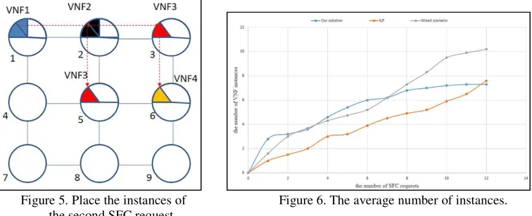
Figure 5. Place the instances of Figure 6. The average number of instances. the second SFC request.
[image:8.612.118.496.70.224.2]There is an example to illustrate the procedure of our algorithm, which is shown in Fig. 4 and Fig. 5. First in Fig. 4, if the resource constraints are satisfied, a SFC with four VNFs will be accepted to be processed in the simplified network topology. The VNFs will be instantiated in four physical nodes, node1, 2, 3 and 6. Each VNF
instance requires one-half circle’s computational resource and the computational resource each VNF requires is represented by one eighth of a circle. They will be processed orderly. The number of VNF instances is four now.
Next in Fig. 5, another SFC with three VNFs is waiting to be accepted. Considering our objective: Minimizing the number of VNF instances implemented, the algorithm will try to reuse the existing VNF instances. For example, it is possible to share VNF instances 1 and 2 implemented at node 1 and 2. While the third VNF of this SFC may
not share VNF instance 3 instantiated by the previous SFC at node 3. It is possible to
instantiate an additional instance in node 5. This is just a kind of scenario and it is not
the optimal answer. The number of instances implemented is five now. If a SFC ends its lifecycle, the computational and bandwidth resources will be released.
Performance Evaluation
Experimental Environment
In this section, we test the performance of our solution and evaluate it. The experimental simulation scenario is designed as a small-scale network. So, the physical network topology is represented by a two-dimensional matrix structure. The value in each element denotes the link delay between two nodes, which is generated within a certain range randomly. Each physical node will be assigned a certain amount of computational resources, and each link is assigned the same bandwidth resource.
We consider four network functions to be virtualized, and they are indiscriminately abstracted into four common VNFs: f1, f2, f3 and f4. There are three different forms of
SFC: 1) f1f2, 2) f1f2f3, and 3) f1f2f3f4, and these SFC requests will be
generated randomly. VNFs in different SFC requests certainly can share the same VNF instance at physical nodes, and they have the same requirements in terms of computational and bandwidth resource. Each VNF instance requires 50% of computational resource at a physical node, while VNF requires 12.5%. The virtual links between VNFs require 20% of bandwidth resource in each physical link.
implement the operation of crossover, and change the value of one gene randomly to implement the operation of mutation. Thirdly, we use roulette gambling method to select the appropriate individuals. This method will choose ones with high fitness to become the parents. While other important parameters concerning with GA are set as the following: population size is recommended about 25; crossover rate can be set to about 0.9; mutation probability is generally set to 0.05; and the genetic iteration is set to about 100. They are all widely used in other papers.
Results and Analysis
Each experiment will be repeated several times to get the averaged results. We will use many different physical network topologies to test each time. The results will be compared with the results of the ILP mentioned, mixed scenario in [9] and our proposed heuristic algorithm.
Firstly, we analyze the number of VNF instances needed to cope with an increasing number of SFC requests. The curves in Fig.6 show the relationship. The average number of instances changes as the number of SFC requests varying from 1 to 15. It can be seen that the number of VNF instances is proportional to the number of SFC requests within a certain range. But after that, the result of our solution will become stable gradually. This is due to the difference in experimental environment and the limitation of network topology scale. The three different scenarios mentioned in [9] will lead to the same result after processing more SFC requests. We can make a reasonable inference from the figure that if we expand the same dimension as the experimental data in [9], it is possible to achieve similar results. Our solution can have a better performance.
Secondly, we analyze the resource utilization of all physical nodes in our experiments. The two curves (orange and gray) in Fig. 7 show the average computational resource utilization of physical nodes in [9]. Regardless of the research platform, the trend follows the similar law. We can observe that, in general, resource utilization tends to be lower when higher numbers of SFCs are being handled. It can be seen that at the beginning, the results are proportional to the number of SFC requests. When dealing with more SFCs, the proportion of physical resources will reach a certain ceiling value. Then it decreases a bit down and becomes stable gradually. It is because of the procedure of resource release. If the earlier accepted SFC ends its lifecycle, the required resources will be released and the resource utilization declines in time. When the number of SFC to be accepted and the number of SFC in processing come to balance, the computational resources utilization will gradually become stable. Our simulation results are similar to the ILP. The limitations of the comparison and analysis results are similar to the previous one.
Figure 7. The average resource utilization. Figure 8. The average delay.
delay, as well as the time to search the optimal solution by GA. The delay of each link is set randomly between 0 and 99ms, and the delay of processing different VNF is set to 10 to 40ms. The curve in Fig. 8 depicts the average delay to instantiate VNF with the number of SFC requests increasing from 1 to 10. We set the max acceptable delay to 200ms. These particularly high delays are mainly due to the forwarding delay. Because the experimental platform and the numerical settings are different, the comparison with other algorithms [9] is not shown in Fig. 8.
Conclusion
NFV is a promising design paradigm and will play an important role in future networks. It is expected to manage network resource efficiently and deliver services dynamically. The implementation of NFV should prevent excessive or less resources allocation. Therefore, it is significant to apply a cost-effective way to place VNFs, which is regarded as an important foundation for NFV’s construction.
In this work, we studied this interesting problem: how to instantiate the least number of VNF instances to process SFC requests in good performance. Then, we proposed an effective solution to achieve high resource utilization and end-to-end delay controllable. From the simulation results, we can reasonably infer that our solution proves effective and performs well for the similar trends and results compared with other algorithm. There is still work to do such as finding the appropriate parameters for GA and build more scientific and advanced experimental platform. We will study on them in future work.
References
[1] D. A. Joseph, A. Tavakoli, and I. Stoica, “A policy-aware switching layer for data centers,” in Proceedings of the ACM SIGCOMM Conference on Data Communication, 2008.
[2] Long Q, Assi C, Shaban K. Network function virtualization scheduling with transmission delay optimization[C]// NOMS 2016 - 2016 IEEE/IFIP Network Operations and Management Symposium. IEEE, 2016:638-644.
[3] W. Xu, Y. Jiang, and C. Zhou, “Problem Statement of Network Functions Virtualization Model. Internet-Draft, draft-xjz-nfv-modelproblem-statement-00,” Active Internet-Draft, IETF Secretariat, Tech.Rep., September 2013.
[4] Mijumbi R, Serrat J, Gorricho J, et al. Network Function Virtualization: State-of-the-art and Research Challenges [J]. IEEE Communications Surveys & Tutorials, 2015:1.
[5] Clayman S, Maini E, Galis A, et al. The dynamic placement of virtual network functions[C]// Network Operations and Management Symposium. IEEE, 2014:1-9.
[6] Rankothge W, Le F, Russo A, et al. Experimental results on the use of genetic algorithms for scaling virtualized network functions[C]// Network Function Virtualization and Software Defined Network. IEEE, 2015:47-53.
[7] Moens H, De Turck F. VNF-P: A model for efficient placement of virtualized network functions[C]// International Conference on Network and Service Management. IEEE, 2014:418-423.
mapping and scheduling of virtual network functions[C]// IEEE Conference on Network Softwarization. IEEE, 2015.