MATLAB BASED MODELING AND SIMULINK PACKAGE FOR DC-DC BOOST CONVERTOR TO ENHANCE LEARNING PROCESS OF POWER
ELECTRONICS.
MUHAMMAD MUJTABA ASAD
A project report submitted in partial fulfilment of the requirement for the award of the Degree of Masters in Technical and Vocational Education
Faculty of Technical and Vocational Education
UNIVERSITI TUN HUSSEIN ONN MALAYSIA
ABSTRACT
ABSTRAK
TABLE OF CONTENTS
CHAPTER CONTENT PAGE
TITLE i
DECLARATION ii
DEDICATION iii
ACKNOWLEDGEMENT iv
ABSTRACT v
TABLE OF CONTENT vii
LIST OF FIGURES xii
LIST OF TABLE xiv
LIST OF ABBREVIATION xvi
LIST OF APPENDICES xviii
CHAPTER 1 INTRODUCTION 1.1 Introduction 1
1.2 Problem Statement 3
1.3 Objective 5
1.4 Hypothesis 6
1.5 Importance of Study 6
1.6 Study Scope 7
1.6.1 Simulation Scopes on Matlab Package 7 1.7 Study Restriction 8
1.9 Different Learning Styles 10
CHAPTER 2 LITERATURE REVIEW 2.1 Introduction 13
2.2 Simulation-Based Learning 15
2.3 Pedagogical Philosophy 16
2.3.1 Pedagogical Approach 16
2.4 Matlab simulation based learning 17
2.4.1 Matlab Simulink for Power Electronics 18
2.5 DC-DC Converters 19
2.5.1 Non Isolated DC-DC Converters 19
2.5.1.1 Buck converter 19
2.5.1.2 Boost Converter 20
2.5.1.3 Buck-Boost Converter 21
2.5.1.4 Cuk Converter 21
2.5.2 Isolated DC-DC Converters 22
2.5.2.1 Fly Back Converter 22
2.5.2.2 Forward converter 23
2.5.2.3 Functions of DC-DC converters 24
2.6 DC-DC converter switching 25
2.7 Advantages of DCM 28
2.8 Disadvantages of DCM 29
2.9 Boost Converter 29 2.9.1 Analysis for switch closed 𝑜𝑛 31
2.9.2 Analyses for switch open (off) 32
2.10 PID Controller 36
2.11 Fuzzy logic controller system 38
2.12 Fuzzification 40
CHAPTER 3 METHODOLOGY
3.1 Introduction 46
3.2 Flow chart for Design Study and Methodology 48
3.3 Sampling 49
3.4 Study Instruments 49
3.5 Pre-Research Questioner 49
3.6 Post-Research Questioner 51
3.7 Boost Convertor Parameters 52 3.8 Fuzzy Logic Controller and Its Operational 53
Methodology
3.9 Rule Base 55
3.10 Data Analysis Procedure For Pre-Research 56 3.10.1Respondent Based On Gender 56 3.10.2Student Response On Pre-Research Questions 57 3.10.3Analysis Results Of Pre-Research Questioner 60 3.11 Reliability and Validity Analysis 61 3.12 Data Analysis Method For Post-Research Questioner 64 3.13 Conclusion 66
CHAPTER 4 RESULTS AND ANALYSIS
4.1 Introduction 67
4.2 Results And Findings 69 4.3 Objective 1: Development of Matlab Simulink 69
Package.
4.3.3 Development Phase 71
4.3.4 Implementation and Evaluation Phase 73
4.4 Objective 2: Investigate The Voltage Outputs 74
4.4.1 Analysis For Open Loop Boost Convertor 74
4.4.2 Analysis For Boost Convertor with PID 76
4.4.3 Analysis For Boost Convertor with Fuzzy 77
4.5 Objective 3: Comparison Between Outputs 80
4.6 Data Analysis Post-Research Questioner Section A 81
4.6.1 Data Analysis Based On Gender 82
4.6.2 Data Analysis Based On CGPA 83
4.6.3 Data Analysis Based On Education 84 4.6.4 Data Analysis Based On Learning Style 85 4.7 Data Analysis Post-Research Questioner Section B 86
4.7.1 Data Analysis Of Objective 4 87
4.7.2 Data Analysis Of Objective 5 88
4.7.3 Data Analysis Of Objective 6 89
4.7.4 Data Analysis Of Objective 7 90
4.8 Results Of Overall Mean and Standard Deviation 92
4.9 Hypothesis Analysis 93
4.9.1 Hypothesis 93
4.9.2 Coefficient Of Determination In Multiple 94
Regression. 4.10 Comment Section Description 96
CHAPTER 5 DISCUSSION, CONCLUSION AND RECOMMENDATIONS
5.1 Introduction 97
5.2 Discussion 98
5.2.1 Respondent Background 98
5.2.2 Ramification Of Matlab Simulink Package 98
5.2.3 Learning From Matlab Simulink Package 99
5.2.4 Response From Matlab Simulink Package 101
5.2.5 Benefits Of Matlab Simulink Package 102
5.3 Analysis Indication 103
5.4 Conclusion 104
5.5 Recommendations 105
5.5.1 Recommendation For UTHM 105
5.5.2 Recommendation For Further Research 106
REFERENCES 107
LIST OF FIGURES
NO Title Page
1.1 ADDIE Model 9
2.1 The Basic Circuit Configuration of the Buck Converter 20
2.2 Basic Circuit of Boost Converter 20
2.3 Basic Circuit of Buck-Boost Converter 21
2.4 Basic Circuit of Cuk Converter 22
2.5 Basic Circuit of Fly-Back Converter 23
2.6 Basic Circuit of Forward Converter 24
2.7 Switching ON and OFF of DC-DC converter 26
2.8 𝑇𝑂𝑁and𝑇𝑂𝐹𝐹pulse 26
2.9 Continuous Conduction Mode 27
2.10 Discontinuous Conduction Mode 27
2.11 𝑖𝐿and𝑉𝐿 when inductor looks like short circuit 28
2.12 A Boost Converter Circuit 30
2.13 The Duty Cycle for Switching Period during Steady State 30 2.14 The Equivalent Circuit of Boost Converter When the 31
Switch S Is Closed 2.15 Analysis for Switch Closed (𝑜𝑛) 32
2.16 The Equivalent Circuit of Boost Converter 33
2.1 8 Control Methods for DC-DC Converters 36
2.19 Proportional-Integral-Derivative (PID) Controllers 37
2.20 Fuzzy Logic Controller Schematic 39
2.21 FLC Overall Structure 39
2.22 The Features of A Membership Function 40
2.23 (A) Triangular Membership Function Shape 42
2.23 (B) Gaussian Membership Function Shape 42
2.23 (C) Trapezoidal Membership Function Shape 42
2.23 (D) Generalized Bell Membership Function Shape 45
2.23 (E) Sigmoidal Membership Function Shape 48
2.24 Weight Average Method Defuzzification 54
3.1 The Overview of the Methodology Flow Chart of 72
this Project. 3.2 Block Diagram of Fuzzy Control System 72
4.3.3 (A) Screen Shot Of Open Loop 72
4.3.3 (B) Screen Shot Of PID 73
4.3.3 (C) Screen Shot Of Fuzzy Logic 73
4.6.1 Sprinkling Of Respondents Based On Gender 82
4.6.2 Sprinkling Of Respondents Based On CGPA 83
4.6.3 Sprinkling Of Respondents Based On Education 84
LIST OF TABLES
NO Title Page
2.1 Example of rule base 42
3.1 The value of all parameters can be determined as below 43
Parameters and values for boost converter 3.10.2 Questions Analaysis of Pre-Rsearch Questions 57
(a),(b),(c),(d),(e),(f),(g) 3.11 Alpha Cronbach Level Of Reliability 61
3.11.1 Results From Validity Reliability 62
3.11.2 SPSS Reliability Analysis 63
3.12 Data Analysis Method 64
4.5 (A) The Features of A Membership Function 80
4.5 (B) Voltage Results From Open Loop 81
4.6.1 Sprinkling Of Respondents Based On Gender 82
4.6.2 Sprinkling Of Respondents Based On CGPA 83
4.6.3 Sprinkling Of Respondents Based On Education 84
4.6.4 Sprinkling Of Respondents Based On Learning Style 85
4.7 Ladell Mean Level 86
4.7.1 Objective 4 87
4.7.2 Objective 5 88
4.7.3 Objective 6 90
4.7.4 Objective 7 91
LIST OF SYMBOLS AND ABBREVIATIONS
µe- Degree of membership function of error
Δe- Degree of membership function of delta of error u- Degree of membership function of voltage output ∨ - Maximum operator
O - Output of COG ˄ - Minimum operator B - Bisector of Area C - Capacitor
CCM - Continuous Conduction Mode che - Change of Error
COG - Centroid of Gravity D - Duty Cycle
DC - Direct Current
DCM - Discontinuous Conduction Mode e - Error
FLC - Fuzzy Logic Controller Fs - Frequency Switching
FKEE – Faculty of electrical and electronics engineering. gaussmf - Gaussian Membership Function
KP - Proportional gain L - Inductor
MF - Membership Function MOM - Mean of Maximum
MOSFET - Metal–Oxide–Semiconductor Field-Effect Transistor NB - Negative Big
NS - Negative Small PB - Positive Big
PID - Proportional Integral Derivative PS - Positive Small
PWM - Pulse Width Modulation R - Resistor
S – Switch
UTHM- University Tun Hussein onn Malaysia VC -Voltage (Calculation)
Vo -Output Voltage
s -Kth - switching cycle Input Voltage Vref- Reference output
ZE – Zero
LIST OF APPENDICES
Appendix Title Page
Appendix A Pre-Research Questionnaire 109 Post-Research Questionnaire
Appendix B Statistical Analysis Data 120
Appendix C Supporting Documents 134
CHAPTER I
INTRODUCTION
1.1 Introduction
Power electronics is, by nature, a multi-disciplinary subject, and for any instructor a challenging course to teach. It is especially demanding course because of variety of topics, such as circuit analysis, signals and systems analysis, and control theory. It is a combination of hands-on experience and solid knowledge of theory provides an active learning environment that leads to successful learning and understanding process.
DC to DC boost converters are important in portable electronic devices such as cellular phones and laptop computers, which are supplied with power from batteries primarily. Such electronic devices often contain several sub-circuits, each with its own voltage level requirement different from that supplied by the battery or an external supply (sometimes higher or lower than the supply voltage) and boost converter (step-up converter) is a DC-DC power converter with an output voltage greater than its input voltage. They provide smooth acceleration control, high efficiency, and fast dynamic response. DC converter can be used in regenerative braking of DC motor to return energy back into the supply, and this feature results in energy saving for transportation system with frequent stop; and also are used, in DC voltage regulation (Rashid, 2004).In many ways, a DC-DC converter is the DC equivalent of a transformer. There are four main types of converter usually called the buck, boost, buck-boost and Boost converters. The main feature of a fuzzy controller is that it can convert the linguistic control rules based on expert knowledge into automatic control strategy. So it can be applied to control systems with unknown or un modeled dynamics. (Ozdemir, 1997)
Mostly, the DC-DC converter consists of the power semiconductor devices which are operated as electronic switches and classified as switched-mode DC-DC converters. Operation of the switching devices causes the inherently nonlinear characteristic of the DC-DC converters. Due to this unwanted nonlinear characteristics, the converters requires a controller with a high degree of dynamic response. Pulse Width Modulation (PWM) is the most frequently consider method among the various switching control method (J. Alvarez-Ramirez, Jan. 2001). In DC-DC voltage regulators, it is important to supply a constant output voltage, regardless of disturbances on the input voltage.
The focus of this research is the development of DC-DC boost convertor Matlab simulink package by using fuzzy logic controller for enhancing the learning process of power electronic course. In this project, Matlab simulink package is used as a platform for students to understand the function of DC-DC boost convertor. After the development of Boost convertor Matlab Simulink will be test on UTHM, Faculty of electrical and electronics engineering students and then evaluate and analyze the effectiveness of this Matlab simulink package with the help of design Post-research questioner which will discuss in chapter 4 of this study.
1.2 Problem Statement
Power electronics is one of the essential course in engineering (electrical and electronics), and the main focus of this course on diploma and degree level on DC-DC boost convertors. DC-DC boost convertors are widely used in industrial applications according to the requirement of project. Firstly, most of the power electronics final year degree students of Electrical engineering they are facing problems during working on hardware without testing on simulation based software, that‟s why they waste a lot of their money and time and sometimes they may damage expensive laboratory equipment‟s of university and Polytechnics because they are working on hardware without any precaution and proper handling.
students of faculty of Faculty of Electrical and Electronic, UTHM are facing same problem in their experimental work which is analyzed from Pre-Research Questioner data of this research for the justification of this problem statement.
For enhancing the learning process of power electronics course, experimental work before working on hardware its better and effective to implement DC-DC convertor on Matlab simulink for sufficient learning outcome and also save costly electrical equipment. Developing the fuzzy controller is cheaper than developing a model based or other controllers for the same purpose. Proportional-Integral- Differential (PID) controllers have been usually applied to the converters because of their simplicity. However, the main drawback of PID controller is unable to adapt and approach the best performance when applied to nonlinear system. It will suffer from dynamic response, produces overshoot, longer rise time and settling time which in turn will influence the output voltage regulation of the Boost converter.
1.3 Objective
The objectives of this project are,
i. To develop a DC- DC Boost convertor Matlab Simulink package to enhance learning process of power electronics course.
ii. To investigates the voltage output for DC-DC Boost converter between open loop, PID controller and fuzzy logic controller through Matlab simulink package.
iii. To compare the output of close loop and open loop DC-DC boost convertor.
iv. To identify the ramifications of Boost convertor Matlab Simulink software package.
v. To analyze the Learning outcomes from Boost convertor Matlab Simulink software package.
vi. To analyze the response from Boost convertor Matlab Simulink software package.
H0 : There is no significant change in the mean value of learning process of DC DC boost convertors by using Matlab simulink package.
1.5 Importance of Study
i. To provide experience and the importance of simulation based power electronic course for final year degree student of electrical engineering.
ii. Students will directly involve in this study and they are final year degree students from Faculty of Electrical and Electronic Engineering (FKEE), UTHM.
1.6 Study Scope
The scopes of this project is to simulate the proposed method of voltage tracking of DC-DC boost converter using Fuzzy controller with Matlab Simulink software for the enhancement of learning process of power electronic students. Analyses of the converter will be done for continuous current mode (CCM) only. The analysis only covered the output voltage based on reading on overshoot ratio, rise time, peak time and settling time. In this project, Matlab simulink package is used as a platform in designing the fuzzy logic controller. This Matlab simulink package is develop to study the dynamic behavior of DC-DC boost converters and performance of proposed controller for the enhancement of learning process of Power electronics students.
1.6.1 Simulation Scopes Of Matlab Simulink
Simulation consists of:
i. This study is restricted and based on student perception. ii. Accomplish by very tight financial and time limit.
iii. The accuracy of study is on depends on the honesty of respondents while answering the questionnaires form.
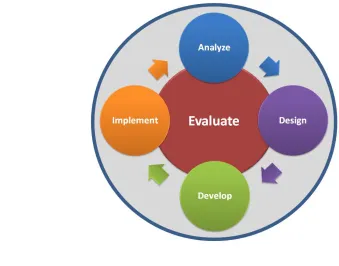
1.8 ADDIE Model Of Instructional Design
Figure 1.1:ADDIE Model For Instructional Design
The Analysis is the most important step in the process. It helps you to determine the basis for all future decisions. A mistake that many beginners make is not conducting a proper analysis at the beginning. It is this analysis that helps you identify your audience, limitations or opportunities, or other important points that will be useful in the design process.
The Design process is the brainstorming step. This is where you use the information obtaining in the Analysis phase to create a program or course that meets the needs of your customer or audience. There are many forms of the design process and it can be very tedious at times. Testing your concepts in the design phase will save you time and money.
phase could require additional assistance for managing server space and technology. The Implementation phase includes more processes than simply presenting the materials developed. While the concepts and materials have been tested throughout the process, the implementation phase can uncover topics that require further development or re-design work. The processes for this phase vary based on the size of the organization, the complexity of the program or course, and the distribution of the materials. This includes such concepts as test pilots, train-the-trainer sessions, and other delivery methods to present the materials.
The Evaluation phase plays an important role in the beginning and at the end of the process. Evaluation objectives reflect much of the discoveries found in the Analysis process. These discoveries include the objectives and expectations of the learner. When looking at the process, you must avoid the thought that it is structured in a chronological order.
1.9 Different Learning Styles
Auditory Learning Style
Auditory learners would rather listen to things being explained than read about them. Reciting information out loud and having music in the background may be a common study method. Other noises may become a distraction resulting in a need for a relatively quiet place.
Characteristics:
• Retains information through hearing and speaking
• Often prefers to be told how to do things and then summarizes the main points out loud to help with memorization
• Notices different aspects of speaking
Visual learners learn best by looking at graphics, watching a demonstration, or reading. For them, it's easy to look at charts and graphs, but they may have difficulty focusing while listening to an explanation.
Characteristics:
• Uses visual objects such as graphs, charts, pictures, and seeing information • Can read body language well and has a good perception of aesthetics • Able to memorize and recall various information
• Tends to remember things that are written down • Learns better in lectures by watching them
Kinesthetic or Hands-On Learning Style
Kinesthetic learners process information best through a "hands-on" experience. Actually doing an activity can be the easiest way for them to learn. Sitting still while studying may be difficult, but writing things down makes it easier to understand.
Characteristics:
• Likes to use the hands-on approach to learn new material • Is generally good in math and science
CHAPTER II
LITERATURE REVIEW
2.1 Introduction
Simulation refers to the application of computational models to the study and prediction of physical events or the behavior of engineered systems. The development of computer simulation has drawn from a deep pool of scientific, mathematical, computational, and engineering knowledge and methodologies. With the depth of its intellectual development and its wide range of applications, computer based simulation has emerged as a powerful tool, one that promises to revolutionize the way engineering and science are conducted in the twenty-first century.
the knowledge and techniques of fields like computer science, mathematics, and the physical and social sciences. As a result, engineers are better able to predict and optimize systems affecting almost all aspects of our lives and work, including our environment, our security and safety, and the products we use and export.
Since fuzzy logic controller can mimic human behavior, many researchers applied fuzzy logic controller to control voltage output. A thorough literature overview was done on the usage of fuzzy logic controller as applied DC-DC Boost Converter.
Ismail, N.F.N. Musirin, I. ; Baharom, R. ; Johari, D (2010) proposed a fuzzy logic controller using voltage output as feedback for significantly improving the dynamic performance of boost dc-dc converter by using MATLAB Simulink software for the better understanding of simulation based learning and teaching of power electronic course. The simulation results are shown that voltage output with fuzzy logic controller with 0% overshoot shows the better performance compared to the open loop circuit (without fuzzy logic controller) whereby it has 80% overshoot.
Md. Shamim-Ul-Alam, Muhammad Quamruzzaman and K. M. Rahman (2010) proposed design of a sliding mode controller based on fuzzy logic for a dc-dc 7 boost converter. Sliding mode controller ensures robustness against all variations and fuzzy logic helps to reduce chattering phenomenon introduced by sliding controller, thereby increasing efficiency and reducing error, voltage and current ripples.
The proposed system is simulated using MATLAB/SIMULINK and also create an effective result on students understanding. This model is tested against variation of input and reference voltages and found to perform better than conventional sliding mode controller.
Based on those related work, the researchers make a great efforts to propose the good to overcome the DC-DC Converter problems.
2.2 Simulation-Based Learning
Simulation based engineering experiments is a technique for practice and learning that can be applied to many different disciplines and types of trainees. It is a technique (not a technology) to replace and amplify real experiences with guided ones, often “immersive” in nature, that evoke or replicate substantial aspects of the real world in a fully interactive fashion. “Immersive” here implies that participants are immersed in a task or setting as if it was the real world.
In the 1980s, during the time when personal computers became less expensive and more simulation software became available, independent groups began to develop simulator systems. Much of this was utilized in the areas of engineering sciences, aviation, military training, medical, nuclear power generation, and space flights.
Simulation-based learning itself is not new. It has been applied widely in the aviation industry (also known as CRM or crew resource management), anesthesiology, as well as in the military and engineering sciences. It helps to mitigate errors and maintain a culture of safety, especially in these industries where there is zero tolerance for any deviation from set standards. (Biggs, 2003).
process in a controlled and safe environment. The skills requirements which can be enhanced with the use of simulation include:
a. Technical and functional expertise training. b. Problem-solving and decision-making skills.
c. Interpersonal and communications skills or team-based competencies.
2.3 Pedagogical Philosophy
Power electronics is, by nature, a multi-disciplinary subject, and represents for any instructor a challenging topic to teach. It is an especially demanding course as it requires assimilation of a broad variety of topics, such as circuit analysis, signals and systems analysis, and control theory.
It is widely accepted that hands-on experience in combination with a solid knowledge of theory provides an active learning environment that leads to successful learning in engineering topics.
An effective power electronics simulation is expected to combine theoretical and experimental aspects of the topics by using state-of-the-art software/hardware tools.
2.3.1 Pedagogical Approach
with interactive learning strategies to reinforce the basic concepts of the power electronics course in the context of the innovative power electronics simulation based laboratory. The tools used in the simulation based laboratory are compatible with industrial-grade platforms and encompass both theoretical aspects of power electronics circuits and practical applications. The simulation based laboratory is built upon prior knowledge and background of the students, and is interdisciplinary with respect to the tools and skills required. For example, it combines knowledge in Digital Signal Processor (DSP)/micro-controller hardware/software platforms with power electronics to design and control the power electronic circuits. This signature aspect of the laboratory is intended to create threads among the related subjects to power electronics and retain the students‟ knowledge across multiple disciplines for the enhancement of student learning. This pedagogical strategy goes beyond the “divide and conquer” strategy wherein each subject is relegated to its own course and then reduced and analyzed. Engineering education has traditionally followed such a strategy so that upon completion of the course, students find it unnecessary to draw upon the information learned from other courses, with the exception of more advanced courses on the same subject. This has been described as a “filtering” or non-retaining mode of education. (Biggs, 2003).
2.4 Matlab simulation based learning
Matlab (matrix laboratory) is a numerical computing environment and fourth-generation
programming language. Developed by Math Works, Matlab
uses the MuPAD symbolic engine, allowing access to symbolic computing capabilities. An additional package, Simulink, adds graphical multi-domain simulation and Model-Based Design for dynamic and embedded systems.
In 2004, Matlab had around one million users across industry. Matlab users come from various backgrounds of engineering, science, and economics. Matlab is widely used in academic and research institutions as well as industrial enterprises.
Simulink, developed by Math Works, is a data flow graphical programming language tool for modeling, simulating and analyzing multi domain dynamic systems. Its primary interface is a graphical block diagramming tool and a customizable set of block libraries. It offers tight integration with the rest of the MATLAB environment and can either drive Matlab or be scripted from it. Simulink is widely used in control theory and digital signal processing for multi domain simulation and Model-Based Design.
2.4.1 Matlab Simulink For Power Electronics
The following section will looks at how the modeling and simulation of a power electronic converter can be carried out using Matlab simulink software.
The blocks which are used to achieve the modeling as follow:
1. Repeating Sequence: this block will be used to generate a number of pulses in terms of time.
2. Sine wave: is used to generate a sinusoidal input with amplitude, frequency and phase. 3. Switch Function (Thy): is used to switch between the sine wave form and the firing pulse which is generated from the repeating sequence.
2.5 DC-DC Converters
The DC/DC converter is a device for converting the DC voltage to step-up or step-down depending on the load voltage required. If the requirement of voltage is step-up then it is necessary to use a boost converter. It the requirement of voltage is step-down, and then it necessary to use a buck converter. Sometimes, both step-up and step-down is required to cover the load, but at different times then it is necessary to use a buck-boost converter. Therefore, different types of DC-DC converters are used for different voltage levels in load. Generally DC/DC converters are divided into two types.
1- Non isolated DC-DC converter 2- Isolated DC-DC converter
2.5.1 Non Isolated DC-DC Converters
2.5.1.1 Buck converter
Figure 2.1: The Basic Circuit Configuration of the Buck Converter
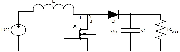
2.5.1.2 Boost Converter
A boost converter or a step up converter is a non-isolated converter. It the most commonly used DC/DC converter, especially used in UPS and PV. This is because battery charge requires high DC voltage to be fully charged. Figure 2.2 shows the basic boost converter. The theory of a boost converter is not complicated as other converters rather. It is simple and straight forward. If the switch, S is ON, the current flows only through the inductor, which has stored energy. When the switch, S is OFF, the energy in the conductor is translated to a capacitor, which usually has a large capacity to store a bigger amount of energy. Finally, this energy converts to load with a high DC voltage.
[image:35.612.145.510.512.619.2]2.5.1.3 Buck-Boost Converter
[image:36.612.187.462.322.467.2]The main components in a buck-boost converter are the same as in the buck and boost converter types, but they are configured in a different way. Figure 2.3 in buck-boost converter, a step-up or step-down voltage can change the value of duty cycle. Nevertheless, in a similar process, once the switch is ON, the inductor begins charging and, the converter is stored with energy. However, once the switch is OFF, the circuit changes into inductor and capacitor simultaneously hence all the stored energy in the inductor is converted to capacitor. One thing that controls the voltage is the duty cycle. If the duty cycle is big, voltage is high in the load. On the other hand, when the duty cycle is small, voltage in the load is low.
Figure 2.3: Basic Circuit of Buck-Boost Converter
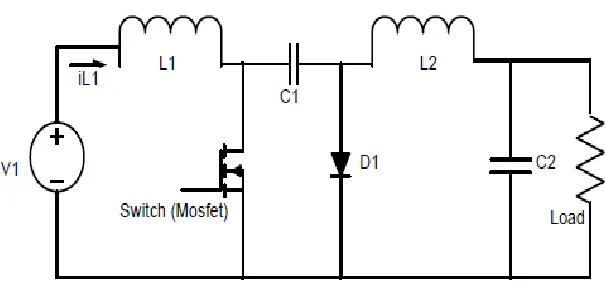
2.5.1.4 Cuk Converter
Figure 2.4: Basic Circuit of Cuk Converter
However, the buck-boost converter such as the Cuk converter can step the voltage up or down, depending on duty cycle. The main difference between the two buck-boost and Cuk converters is that, the series of inductors at both input and output record much lower current ripple in both circuits.
2.5.2 Isolated DC-DC Converters
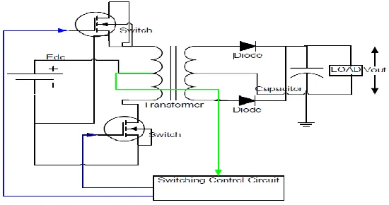
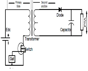
2.5.2.1 Fly Back Converter
than many other circuits but it‟s simple topology and low cost makes it popular in low output power range.
Figure 2.5: Basic Circuit of Fly-Back Converter
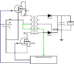
2.5.2.2 Forward converter
forward converter an attractive choice for high power applications.
Figure 2.6: Basic Circuit of Forward Converter
2.5.2.3 Functions of DC-DC converters
The DC-DC converter has some functions. These are:
i. Convert a DC input voltage Vs into a DC output voltage Vo.
ii. Regulate the DC output voltage against load and line variations.
5.5.2 Recommendations for Further Research Study
i. Recommendations for the production of Matlab simulink for other power electronics topics and experimental.
ii. Include the rules of fuzzy logic. When more the rules of fuzzy logic, the output of fuzzy logic would more precise. For this project has used 25 rules so for future works, 49 rules could be adopted.
REFERENCES
Ashfaq Ahmed, 1999, Power Electronics for Technology, page(s): 269-303.
Daniel W.Hart, 1997, Introduction to Power Electronics, page(s):185-204.
Guanrong Chen, Trung Tat Pham, 2001, Introduction to Fuzzy Sets, Fuzzy logic, and Fuzzy Control Systems.
Muhammad H. Rashid, Second Edition, Power Electronics Circuit, Devices, and
Applications, page(s) :303-323.
GuangFeng, Wangfeng Zhang, Yan-FeiLui, An Adaptive current Mode fuzzy Logic
Controller for Dc to Dc Converter, Applied Power Electronics Conference and
Exposition, 2003, APEC ‟03.Eigtheenth Annual IEEE,9-13 Feb,2003, vol.2,page(s): 983-989.
Mattavelli, L.Rossetto, G.Spiazzi and P.Tenti, General-Purpose Fuzzy Controller for
DC-Dc Converter, Proceedings of 1997, IEEE Transactions On Power
Electronics, 1 January 1997, vol.12, no.1.
Yonis Buswig , Yonis, Mohammed (2011). Development of a DC-AC power
conditioner for wind generator by using neural network. Masters thesis,
Universiti Tun Hussein Onn Malaysia.
W.M.Utomo, A. B. (April 2011). Online Learning Neural Network Control of
Buck-Boost Converter. Eighth International Conference on Information Technology:
New Generations (ITNG).
Ismail, N. I., Baharom, R., & Johari, D. (2010). Fuzzy logic controller on DC/DC boost converter. Power and Energy (PECon), 2010 IEEE International Conference .
Kuala Lumpur.
Jantzen, J. (2007). Foundations of Fuzzy Control. West Sussex PO19 8SQ, England: John Wiley & Sons Ltd.
Adel E. El-kholy and A. M. Dabroom, (2006): Adaptive Fuzzy Logic Controllers for DC
Drives: A Survey of the State of the art, Journal of Electrical Systems, pp.
116-145.
J.-S. Roger Jang, (1997): Fuzzy Logic Toolbox User’s Guide COPYRIGHT 1984 - 1997 by The MathWorks, Inc. All Rights Reserved Cheng- Yuan Liou and Yen-Ting Kuo.
Collofello, J.S., et al. Using Software Process Simulation to Assist Software Development Organizations in Making Good Enough Quality Decisions. Summer Computer Simulation Conference, 1998 (SCSC98).