! "
# # "$ % %#
& ''' (
Integrated Model-based Test Case Generation
Yujian Fu*
Department of Computer Science School of Engineering and Technology
Alabama A&M University Normal, AL 35762 USA
Shal Li Department of CETL
School of Education Alabama A&M University
Normal, AL 35762 USA [email protected]
Sudip Bhattacharjee Department of Civil Engineering School of Engineering and Technology
Alabama A&M University Normal, AL 35762 USA [email protected]
Zhijiang Dong Department of Computer Science Middle Tennessee State University
Murfreesboro, TN 37132 USA [email protected]
Abstract:Model-based test case generation provides a solid foundation for the software quality assurance and gains more and more attention to
the industries. It is important to perform software testing as early as possible to detect faults, reduce software development time and cost. Many researchers have considered using UML diagrams to generate test cases. Few work on the test case generation using combination of sequence diagram and statechart diagrams is reported in literatures. In this paper, we present an integrated approach to generating test cases from sequence diagrams using UML2.x syntax. The approach combines UML2 sequence diagrams and statecharts hierarchically and generate test paths based on message flow graph. We also define various coverage criteria to generate test paths. We have applied it to a case study to investigate its fault detection capability. The results show that the proposed approach effectively detects all the seeded faults when complying with the most demanding adequacy criterion and still achieves reasonably good results for less expensive adequacy criteria. As a result, this work provides a solid foundation for further research on automatic test case generation, coverage criteria analysis of sequence diagram based object oriented testing.
Keywords:model-base testing; sequence diagram; statechart diagram; test case; test criteria
I. INTRODUCTION
There is an increasing need for effective testing of software intensive system for quality assurance. In the addition, the growing application areas of web applications and e-commerce is growing in size, become more complex and require more reliable than most traditional applications. Model-based test case generation provides a solid foundation for the software quality assurance and gains more acceptance to the software practitioners. It is important to performance software testing as early as possible to detect faults, reduce software development time and cost. Many researchers have considered using UML diagrams to generate test cases. Few work on the test case generation using combination of sequence diagram and state chart diagrams is reported in literatures. In this paper, we present an integrated approach to generating test cases from the combination of sequence diagrams and state chart diagrams using UML2.x syntax.
The Unified Modeling Language (UML) has emerged as the de facto standard for analysis and design of different kinds of systems. UML provides a variety of diagramming notations for capturing design information from different perspectives. In recent years, researchers have realized the potential of UML models as a source of information in software testing [1, 7, 8, 9, 12, 15, 18, 24, 26, 29, 37, 32, 38, 34, 39, 17]. Many UML design artifacts have been used in different ways to perform different kinds of testing. For instance, UML statecharts have been used to perform unit
testing, and interaction diagrams (collaboration and sequence diagrams) have been used to test class interactions. More and more software developers use UML and associated visual modeling tools as a basis to design and implement their applications. In addition, UML sequence diagram is widely used for specifying the dynamic behaviors of classes and contains necessary information about object communications in terms of object life lines that is more propitious to object-oriented software testing. Therefore, in the research reported in this paper, UML sequence diagram are used as a basis to generate message flow graph (MFG) hierarchically. Firstly, we discuss an approach to generated hierarchical MFG based on sequence and state chart diagram of corresponding objects. After that, a verification method is provided for the coverage criteria.
II. BACKGROUND
In this section, we discuss on UML 2.0 sequence diagrams with the new enriched features – fragments (Fig. 1).A sequence diagram precisely specifies the set of objects and the sequences of message exchanges that are involved in various scenarios. UML 2.x sequence diagram provides a mechanism known as combined fragments also known as interaction segments. A combined fragment represents the control structures of program by enclosing one or more processing sequences in a frame which are executed under specific named circumstance called fragment operators. There is a facility for providing 12 different types of fragment operators. We briefly discuss only those interaction operators which are used in this work.
Combined fragment loop: A loop fragment indicates that the messages within the operand are to be repeated a number of times. The interaction constraint of a loop operand may include a lower and an upper limit specifying iterations of the loop as well as a Boolean expression. The loop fragment describes the test to be performed before the first execution of the messages in the loop operand indicating a pre-test form of loop. Since it is impractical to include all message paths of a loop fragment, we consider a predicate node coverage criterion (defined in Section 4.2) to generate a test set based on selection of similar paths.
Combined fragment alt and opt: The fragments alt and
opt denote a choice of behavior which is controlled by an interaction constraint. The alt fragment indicates if the alt
condition is satisfied, the program goes to the alt fragment. While the opt indicates an optional path only if the opt
condition is met. The difference is alt provides an exclusive or choice, while opt provide another branch. We denote this choice of behavior as selection and associate with predicate node coverage criterion. The chosen operand has a constraint evaluated to true.
III. RELATED WORK
Traditional testing strategies for procedural programs, such as data flow analysis and control flow analysis cannot be directly applied to OO programs [22]. Extensions of these techniques for OO programs have been proposed by Buy et al. [9] and Martena et al. [25]. A structural test case generation strategy by Buy et al. [8] generates test cases through symbolic execution and automates deduction for the
data flow analysis of a class. Kung et al. [20] proposed an idea to extract state models from the source code, whereas others suggest test generations from pre-existing state-models [12, 29, 13, 33]. In the sections below, we will discuss more specific UML-based testing technique.
An approach was proposed by Tse and Xu [32] to deriving test cases from Object Test Models (OTM). State space partitions of the attributes of a class are used with the OTM to generate a test tree. The actual test cases are derived from the test tree. Nori and Sreenivas [26] have proposed a specification-based testing technique that splits the specifications of a class into structural and behavioral components. Structural aspects define the attributes and method specifications of a class, whereas state machine is used to defined the behavioral component that describes the sequence of method invocation. In the work of [12, 30], an idea of converting test generation into an AI planning problem was proposed. UML statecharts are processed by planning tools and used to produce AI planning specifications. The test cases are generated based on the processed statecharts. Another example of statecharts based test case generation technique was proposed by Kim et al. [18]. These statecharts are transformed to Extended Finite State Machines (EFSMs) to generate test cases and then use traditional control and data flow analysis on the generated test cases.
Several works have been done based on state-chart and finite state machine. In the work of [28], Li et al. presented an approach to testing specific properties of reactive systems. Kim et al. [22] used statecharts to generate test sequences for Java-based concurrent systems. Kansomkeat and Rivepiboon [21] have converted UML statecharts into an intermediate model known as Testing Flow Graph (TFG). This graph reduces complexities of statecharts and produces a simple flow graph. Test cases are finally generated by traversing the TFG using state and transition coverage criteria. The proposed methodology was evaluated using mutation testing. Results of an experiment carried out to validate the application of Round Trip Test Strategy [6] on UML statecharts are presented in Briand et al. [8]. Authors also propose improvements on the strategy based on the analysis of these results. Swain et al. has proposed a method of statecharts and activity model based testing technique by constructing an intermediate model named state-activity diagram (SAD) [40]. Besides, some recent work [13] was proposed using formalization on the statechart diagram to perform model-based testing. In the work of [3], a semantic model is proposed using the labeled transition system. The formalization of model based testing represents a new trend of state based testing.
Although many works had been done on the OO testing of sequence diagram and statecharts diagram, this work is different from the above unit level testing in two aspects. First, this work presents a hierarchical synthesized approach to sequence diagram testing using a message flow graph (MFG). The proposed MFG is generated from the statechart that supports message generation in the sequence diagram. Secondly, the hierarchical structure provides a novel graphic based testing technique for OO program validation.
approach to convert use case diagram and sequence diagram into OMDAG, which is used to generate integration tests. Basanieri and Bertolino [5] have presented a User Interaction Testing (UIT) model to perform integration testing. A UIT is generated from use cases and UML sequence diagrams. Abdurazik et al. have discussed a static checking of source code and measuring adequacy of a test suite based on collaboration diagrams [1]. The approach generates the test cases by applying traditional control and data flow analysis on collaboration diagrams. TEst Sequence generator (TESTOR) [35] is an approach used to generate integration tests using UML statecharts and collaboration diagrams for component based systems. The behavior of each component is specified in the form of UML statecharts, while the test directives are specified in the form of UML collaboration diagrams. The SeDiTec [14] approach is used for testing interactions between the classes involved in a sequence diagram. Badri et al. [4] have used use cases and collaboration diagrams to generate integration test cases. Another approach for UML based integration testing is proposed by Le Traon and Jeron et al. [41]. This approach uses UML class diagram and generates an intermediate model known as TD Graph (TDG). This graph has three types of dependencies: Class to Class, Class to Method, and Method to Method dependency. This information was further used to determine the ordering of classes. Briand et al. [10] have discussed how to determine class test orders for integration testing. An approach was proposed in the work of [10] to using UML class diagrams and finding a class test order which minimizes the number of stubs required for integration testing.
IV. AN UML-BASED INTEGRATED APPROACH TO TEST
CASE GENERATION
The run-time behavior of an object-oriented system is modeled by well-defined sequences of messages passed among collaborating objects. In the context of UML, this is usually modeled as interaction diagrams (sequence and/or collaboration diagrams). In many cases, the states of the objects sending and receiving a message at the time of message passing strongly influence their behavior in following aspects:
• An object receiving a message can provide
different functionalities in different states.
• Certain functionalities may even be variable or
unavailable if the receiving object is not in the correct state.
• The functionality of providing object may also depend on the states of other objects including the sending object of a message.
In this work, a graph based testing technique is proposed, which is on the idea that the communication between objects should ideally be exercised (represented by sequence diagram) for all possible states of the objects involved (statecharts diagram). This is of particular importance in the context of OO software as many classes exhibit an interaction state-dependent behavior. Such testing objective is implemented by generating a graph-based testing approach and testing path on message flow graph (MFG) on the defined criteria. The proposed technique can be applied
during the integration test phase, right after the completion of class testing. It consists of three steps:
1. Message Flow Graph (MFG) Generation: We investigate the sequence diagram of the (sub)system, and generate corresponding MFG following the MFG generation algorithm (will be discussed in the following section).
2. Hierarchical Testing Path Generation: Based on the MFG of sequence diagram, for each object that we concern, we refer the state-chart diagram and generate a MFG for some node of MFG.
3. Coverage Criteria: We test the sequence diagram against the coverage criteria that we defined.
In the following sub-sections, we describe the proposed testing technique in greater detail with the help of a simple example.
A. Definitions
First, we introduce message flow graph generation. As we see, one of the basic communications among objects is message passing. In sequence diagram, we represent all communications as messages. Based on the sequence diagram and each object’s behavior (state-chart diagram), we can build a message flow graph (MFG).
In this work, we refer message to be as object, expression, primary variable, and other specific terms defined in UML2. For instance, a message can be Students =
new Student() which indicates an object is instantiated. An arithmetic expression z = x+y, a variable double salary, or a stereo type << create >> can be a message. Therefore, in this work, term refers to any legal statement that can be allowed to used in sequence diagram and state-chart diagram in UML2.
In the next, we first define Message Flow Graph (MFG) that would be used in the description of our methodology.
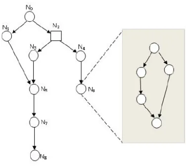
Definition 1 (Message Flow Graph (MFG)) Message Flow Graph (MFG) is defined as a directed graph with (N, E, L,
V), where
• N is a set of nodes, which represent a set of messages that connect objects in the sequence diagram, denoted by circles.
• E is a set of edges, which represent flow direction between objects, and are denoted by arrows. • L is a label function that maps each node and edge
to a set of terms (alphabets (constants and variables) and expressions on alphabets), and • I is a set of initial nodes that indicate the starting of
the program.
Figure 2. An example of MFG.
Next step, we can define dependency path as follows.
Definition 2 (Dependency Path (DP)) Given a MFG G =<
N, E, L, I >, a dependency path (DPi) in G from node ni to
node nj is defined as a sequence of connected acyclic nodes from node ni to node nj in G. For any node nk G, and nk ∉ DPi, there does not exist a dependency path Dpi’such that nk DPi’and DPi DPi’.
In Fig. 1, N0-N1-N5-N7-N8 is a DP. To generate test cases, our purpose is to find the enough independent dependency path (DP) from a completed MFG.
Definition 3 (Independent Dependency Path (IDP)) Given a MFG G =< N, E, L, I >, two dependency paths (Dpi, DPj
G) are independent from each other iff there is at least one node (ni) in one DP (DPi) that is not covered in another DP (DPj), i.e. ni DPi ni ∉ DPj, where ni G,Dpi, DPj G.
To identify IDP, a key issue is to find the predicate node, since predicate node usually is the one that split the program to branches. Here we define predicate node as follows.
Definition 4 (Predicate Node) Any boolean condition that needs to be evaluated can be represented by a predicate node. A predicate node is associated with more than one edges that have logic relation.
Graphically, a predicate node is denoted by a box, and anyregular node as a circle graphically. In Fig. 1, node N2 is a predicate node, and others are regular nodes. Predicate nodes take the program to multiple paths and act as the key nodes of program branches. Predicate nodes are usually by more than one dependency path. For example, in Fig 1, N0-N2-N3
-N5-N7-N8 and N0-N2-N4-N6 are two IDPs regarding to predicate node N2.
B. Generation of MFGs
This is a systematic approach to generate test cases based on UML2 sequence diagrams. Given any sequence diagram
SD in UML2, we have following two big steps in pseudocode form. Subsequently this method is explained using an example.
1. First, for any message that labeled in SD, we generate a node by following life line of each object. Each node has affiliation of its owner
(object), and we use dot notation to denote the owner relation.
Figure 3. A hierarchical MFG of Example of Fig. 2.
2. For message mi that involves internal state
transitions (such as method invocation, object creation, and more actions), we generate a subset of MFG for the node (mi).
Therefore, each node may be hierarchically represented by a set of nodes and edges that form a MFG. By traversing this MFG, we can tell if the message mi causes the object’s
state transition. In addition, we can tell if message mi+1 is the one after message mi of object execution. This approach can
connect black-box testing on the inter-class level with white box testing on the intra-class level. The advantages can be not only we can tell if a message is passed properly when an error is detected, but also can we tell internally what causes the message not passed properly internally of the object.
For example, in Fig. 2, assume node N6 involve a series of state transitions, then we can generate a subset of MFG
GN6 for it (Fig. 3).
Definition 5 (MFG of Sequence Diagram (SD)) Let sequence diagram SD be defined as SD, < O, M, Ix >, where O be the set of object, M be the message set of a class instance; Ix be the set of index of all messages in SD. Let MFG G be the message flow graph of sequence diagram (SD), where GS D =< N, E, L, I > and
• N is the set of all the observable messages mi of set
M, where mi M;
• E is the set of message communication sequences, e.g., there is message mi M and mi+1 M, the correspond nodes ni; ni+1 N form an edge < ni;
ni+1 >.
• L is the set of any message identifiers or pseudo code.
• I is the set of initial nodes ninit, where init Ix, and
i Ix, init i.
[image:4.612.364.552.80.250.2]message used in the MFG to including states. Therefore, we can extend the above two-step generation algorithm to the state-chart diagram by following steps:
1. Generate a node in the subset MFG for each state in the state-chart diagram.
2. Generate a predicate node for each evaluation condition defined in the label of a transition.
3. Generate an edge for each transition between two states.
4. Generate a label for each label of a transition.
C. Generation of Predicate Nodes
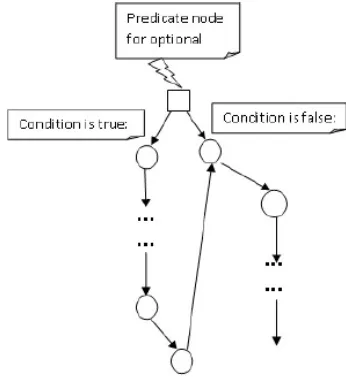
Any fragment in sequence diagram (of UML2) can generate a predicate node whose condition is evaluated to be a boolean value. The fragment with the condition is formed a predicate node. Each predicate node can cause more than one execution branches. Corresponding to fragment of sequence diagram of UML2, therefore, we can have three types of predicate node:
1. Alternative predicate node: for ALT fragment, we have an alternative predicate node which introduces the program to two different path depending on the condition satisfaction.
2. Loop predicate node: for LOOP fragment, we have an iteration predicate node with regarding to condition. The predicate node takes the program to a certain path when the condition is met. Otherwise, the predicate node takes the program to a node that outside the iteration.
3. Optional predicate node: for OPT fragment, there is a condition defined. If the condition is evaluated to be true, then execute this optional part; otherwise, skip the optional fragment. A predicate node of MFG is shown in Fig. 3.
In addition, we have predicate nodes for state-chart diagram. The predicate node is generated whenever there is guard condition labeled for a transition or a state action.
Similarly, the predicate node indicates different execution path inside the object depending on the evaluation of the condition.
D. Testing Criteria
Given the UML-based message and state transition description, the test criteria that includes sequence diagram and statechart diagram contains following rules:
1. All nodes coverage: Each message of sequence diagram and each state in the state-chart diagram have to be tested at least once.
2. All edges coverage: Each observable message passing between two objects of sequence diagram has to be tested at least once. In the subnet of MFG, Each transition in each state-chart diagram has to be tested at least once.
3. All edges coverage: Each observable message passing between two objects of sequence diagram has to be tested at least once. In the subnet of MFG, Each transition in each state-chart diagram has to be tested at least once.
[image:5.612.358.531.62.256.2]4. All independent dependency path coverage: Each IDP of the generated MFG has to be tested at least once.
Figure 4. Predicate node generation of optional fragment.
E. Automatic Testing Path Generation
As the discussion above, atomic generating independent message dependency path is the essential element of integrating testing. As compound message dependency path is related to sequence diagram and statechart diagram, the generation of message dependency path concerns the parse of both sequence and statechart diagrams. In this work, we define both sequence and statechart diagrams in XML format so that it’ll be easily to be read and analyzed.
In order to solve the generation problem precisely, we make two assumptions as follows.
• UML Statechart diagram here is deterministic, consistent, and self-contained. There is no sub state, nested state and concurrent state. Only message event might be taken account of.
• Message dependency path here is based on life line order and mapping relationship of the message in sequence diagram and the actions in state-chart diagram.
Let M be the message set of class instance; Gm be the set
of guard conditions with respect to message m (m M); p be independent MDP with respect to message m.
Generating atomic message dependency path from UML sequence and state-chart diagram comprises the following steps:
• Extract information from UML sequence and statechart diagram, and creating message connecting table.
• Identify message dependency path from sequence diagram and message response table.
• Generate a hierarchical MFG based on the message
connecting table and diagrams.
• Generate a set of independent message dependency paths from MFG.
Let sequence diagram S D be defined as S D ,<O, M, I >, where O be the set of object, M be the message set of a class instance; I be the set of index of all messages in SD. Let G
be the MFG of S D, where G =< N, E, L, I >.
Let G1 be top level MFG, then the number of node in G1 is |M|. Let G2 be next level MFG of all objects oi O, and
G2 = iGoi . For a MFG that have m IDPs in the G1, if there is one node i has next level MFG G2, where G2 has n IDPs, then total IDP of the MFG G is m + n.
For example, in Fig. 2, there are 5 IDPs considering the hierarchy representation of node N6.
V. CASE STUDY
In order to validate the effectiveness of our proposed approach, we implemented the web based car rental system (CRS) example using the Java language, and generated test cases by seeding faults to the diagram. This strategy is well established for assessing test techniques and has shown to yield useful results [2].
A. Experimental Set Up
[image:6.612.97.225.383.589.2]We will consider four different criteria that influence the message flow graph coverage: all nodes, all edges, all IDPs and all predicate nodes criterion. This setup option determines the complexity of the path generation. The number of paths generated is only dependent on the chosen criteria. Later in the generation, some paths may be determined to be infeasible due to the data inputs and guard conditions.
Figure 6. Generated MFG of the sequence diagram in Fig. 5.
B. Result and Discussion
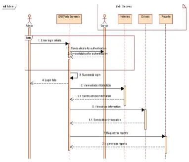
The sequence diagram of administrator of online car rental system is shown in Fig. 3. Following above steps, we can generate a G1 level MFG which is shown in Fig. 4.
For our example presented in Figure 4, there are two coverage criterions will yield the same number of results: For both all nodes and all IDPs criteria, three paths are generated. This is because of two reasons – a) our example is too simple, it does not show hierarchical invocation of methods in other objects, and b) this sequence diagram has logic errors. However, the criterion of predicate node will produce fewer paths: only one path is generated to cover the only predicate node.
Test cases can be generated from each sequence diagram to verify the described functionalities. In the example of online car rental system for administrator, the top level and second level test paths can be tested in isolation. We can test the top level first, in which case, we assume the hierarchical nodes temporarily valid in the second level. There are 52 test cases generate for two levels. It is also extremely important to verify the internal execution sequences of each message. That is, to specify one or more sequences that convey among objects and how many combinations of functionalities can archive the communication. Those combinations can be represented as testing paths, which explicitly represent a set of state transition performed in a particular order of a (more) object(s).
All errors are identified for the embedded 17 faulty. We have fixed 16 seeded errors in the example. The only one that is not fixed is because it’s too straightforward – it can be fixed by switch the order of messages.
C. Analysis
Test cases can be generated from each sequence diagram to verify the described functionalities. In the example of online car rental system for administrator, the top level and second level test paths can be tested in isolation. We can test the top level first, in which case, we assume the hierarchical nodes temporarily valid in the second level. It is also extremely important to verify the internal execution sequences of each message. That is, to specify one or more sequences that convey among objects and how many combinations of functionalities can archive the communication. Those combinations can be represented as testing paths, which explicitly represent a set of state transition performed in a particular order of a (more) object(s).
All errors are identified and fixed in the example. It is very efficient to use the hierarchical testing approach and perform the test separately. According to our experiment, it is much faster to test sequence diagram isolate than test it integrated.
Table I. Generated Test Path
Criteria G1 Test Path G2 Test Path Total Test Path
All nodes 3 15 18
All edges 4 14 18
All IDPs 3 10 13
VI. CONCLUSION AND FUTURE WORK
In this paper, we have presented a new strategy for class integration testing that is based on a hierarchical approach that combines information from sequence diagram and statechart
[image:6.612.142.473.630.679.2]integration testing. For instance, if the functionality provided by an object depends on the message of other objects, then the proposed technique can effectively detect faults occurring due to invalid object messages.
We ran a carefully designed case study using a prototype tool and generated 13 faulty versions of the system under test using 8 carefully selected seeding faults. The empirical results show that the proposed approach effectively detects various kinds of faults communicated among objects. In particular, the all IDP criterion successfully detected all of the seeded faults and is particularly effective at detecting faults related to the messages of interacting classes.
A limitation is that the case study presented in this paper is still in limited size and may not be representative of an industrial system. Industrial case studies are required to carefully analyze the cost-benefit of the proposed integration testing strategy in a realistic context.
VII. ACKNOWLEDGMENT
The authors would like to thank all reviewers for their kind comments and valuable suggestions.
VIII. REFERENCES
[1] A. Abdurazik and J. Offutt. Using UML collaboration diagrams for static checking and test generation. Pages 383 – 395. Springer, 2000.
[2] J. H. Andrews. Is mutation an appropriate tool for testing experiments. In In ICSE 05: Proceedings of the 27th international conference on Software engineering, pages 402–411. ACM Press, 2005
[3] H. R. Asaadi, R. Khosravi, M. Mousavi, and N. Noroozi. Towards Model-Based Testing of Electronic Funds Transfer Systems, May 2010.
[4] M. Badri, L. Badri, and M. Naha. A use case driven testing process: towards a formal approach based on uml collaboration diagrams. In the 3rd International Workshop on Formal Approaches To Testing of Software FATES 2003, volume 2931 of Lecture Notes in Computer Science, pages 223–235, Berlin, Heidelberg, Feb 2003. Springer-Verlag.
[5] F. Basanieri and A. Bertolino. A practical approach to UML-based derivation of integration tests. In 4th
International Software Quality Week Europe, November 2000.
[6] R. V. Binder. Testing Object-Oriented Systems-Models,
Patterns, and Tools. Addison-Wesley Professional, Novmember 1999
[7] K. Bogdanov. Automated Testing of Harels statecharts. PhD thesis, University of Sheffield, 2000.
[8] L. C. Briand, M. Di Penta, and Y. Labiche. Assessing and improving state-based class testing: A series of experiments. IEEE Transaction on Software Engineering, 30(11):770–793, 2004.
[9] L. C. Briand and Y. Labiche. A uml-based approach to system testing. In UML’01: Proceedings of the 4th International Conference on The Unified Modeling Language, Modeling Languages, Concepts, and Tools, pages 194–208, London, UK, 2001. Springer-Verlag. [10] L. C. Briand, Y. Labiche, and Y. Wang. An investigation
of graph-based class integration test order strategies. IEEE Transaction on Software Engineering, 29(7):594–607, 2003.
[11] U. Buy, A. Orso, and M. Pezz. Automated testing of classes. In Proceedings of the International Symposium on Software Testing and Analysis, pages 39–48, New York, NY, USA, 2000. ACM Press.
[12] U. Buy, A. Orso, and M. Pezze. Automated testing of classes. SIGSOFT Softw. Eng. Notes, 25(5):39–48, 2000. [13] V. A. de Santiago Junior, M. Cristia, and N. L.
Vijaykumar. Model based test case generation using statecharts and Z: A comparison and a combined approach. Technical Report INPE-16677-RPQ-850, 2010. [14] F. Fraikin and T. Leonhardt. Seditec ” testing based on
sequence diagrams. In ASE ’02: Proceedings of the 17th IEEE international conference on Automated software engineering, page 261, Washington, DC, USA, 2002. IEEE Computer Society.
[15] P. Fr¨ohlich and J. Link. Automated test case generation from dynamic models. In ECOOP ’00: Proceedings of the 14th European Conference on Object-Oriented Programming, pages 472–492, London, UK, 2000. Springer-Verlag.
[16] L. Gallagher, J. Offutt, and A. Cincotta. Integration testing of object-oriented components using finite state machines: Research articles. Softw. Test. Verif. Reliab., 16(4):215–266, 2006.
[17] A. Hartman and K. Nagin. The agedis tools for model based testing. SIGSOFT Softw. Eng. Notes, 29(4):129– 132, 2004.
[18] J. Hartmann, C. Imoberdorf, and M. Meisinger. Uml-based integration testing. In ISSTA’00: Proceedings of the 2000 ACM SIGSOFT international symposium on Software testing and analysis, pages 60–70, New York, NY, USA, 2000. ACM.
[19] P. C. Jorgensen. Software Testing: A Craftsman’s Approach, Third Edition. AUERBACH, Feburuary 2008. [20] P. C. Jorgensen and C. Erickson. Object-oriented
integration testing. Commun. ACM, 37(9):30–38, 1994. [21] S. Kansomkeat and W. Rivepiboon.
Automated-generating test case using uml statechart diagrams. In
SAICSIT ’03: Proceedings of the 2003 annual research conference of the South African institute of computer scientists and information technologists on Enablement through technology, pages 296–300, , Republic of South Africa, 2003. South African Institute for Computer Scientists and Information Technologists.
[image:7.612.76.267.206.370.2]100–109,Washington, DC, USA, 2005. IEEE Computer Society.
[23] Y. Kim, H. Hong, D. Bae, and S. Cha. Test cases generation from uml state diagrams. Software, IEE Proceedings, 146(4):187–192, 1999.
[24] Y. Kim, H. S. Hong, S. Cho, D. H. Bae, and S. D. Cha. Test cases generation from uml state diagrams. In In IEE Proceedings: Software, pages 187–192, 1999.
[25] D. C. Kung, P. Hsia, Y. Toyoshima, C. Chen, and J. Gao. Object-oriented software testing: Some research and development. In HASE ’98: The 3rd IEEE International Symposium on High-Assurance Systems Engineering, pages 158–165, Washington, DC, USA, 1998. IEEE Computer Society.
[26] D. C. Kung, N. Suchak, J. Gao, P. Hsia, Y. Toyoshima, and C. Chen. On object state testing. In in Proceedings of Computer Software and Applications Conference, pages 222–227. IEEE Computer Society Press, 1994.
[27] S. Li, J. Wang, and Z.-C. Qi. Property-oriented test generation from uml statecharts. In ASE ’04: Proceedings of the 19th IEEE international conference on Automated software engineering, pages 122–131, Washington, DC, USA, 2004. IEEE Computer Society.
[28] W. Linzhang, Y. Jiesong, Y. Xiaofeng, H. Jun, L. Xuandong, and Z. Guoliang. Generating test cases from uml activity diagram based on gray-box method. In
APSEC ’04: Proceedings of the 11th Asia-Pacific Software Engineering Conference, pages 284–291, Washington, DC, USA, 2004. IEEE Computer Society. [29] G. A. D. Lucca, A. R. Fasolino, and U. de Carlini.
Recovering use case models from object-oriented code: A thread-based approach. In Reverse Engineering, Working Conference on, page 108, Los Alamitos, CA, USA, 2000. IEEE Computer Society.
[30] V. Martena, A. Orso, and M. Pezz´e. Interclass testing of object oriented software. In ICECCS ’02: Proceedings of the Eighth International Conference on Engineering of Complex Computer Systems, page 135, Washington, DC, USA, 2002. IEEE Computer Society.
[31] A. V. Nori and A. Sreenivas. A technique for model-based testing of classes. In Proceedings of the Second International Workshop on Software Engineering Tools and Techniques, 2001.
[32] J. Offutt and A. Abdurazik. Generating tests from uml specifications. In R. France and B. Rumpe, editors,
UML’99 -The Unified Modeling Language. Beyond the Standard. Second International Conference, Fort Collins, CO, USA, October 28-30. 1999, Proceedings, volume 1723, pages 416–429. Springer, 1999.
[33] J. Offutt, S. Liu, A. Abdurazik, and P. Ammann. Generating test data from state-based specifications.
Software Testing, Verification and Reliability, 13(1):25– 53, March 2003.
[34] P. Pelliccione, H. Muccini, A. Bucchiarone, and F. Facchini. Testor: deriving test sequences from model-based specifications. In the Eighth International SIGSOFT Symposium on Component-based Software Engineering (CBSE 2005), volume 3489 of Lecture Notes in Computer Science, page 267C282, Berlin / Heidelberg, 2005. Springer.
[35] O. Pilskalns, A. Andrews, S. Ghosh, and R. France. Rigorous testing by merging structural and behavioral uml representations. In Sixth International Conference on the Unified Modeling Language (UML 2003), volume 2863/2003, pages 234–248, Berlin/Heidelberg, 2003. Springer.
[36] H. Reza, K. Ogaard, and A. Malge. A model based testing technique to test web applications using statecharts. In
ITNG ’08: Proceedings of the Fifth International Conference on Information Technology: New Generations, pages 183–188, Washington, DC, USA, 2008. IEEE Computer Society.
[37] M. Riebisch, I. Philippow, and M. G¨otze. Uml-based statistical test case generation. In NODe ’02: Revised Papers from the International Conference NetObjectDays on Objects, Components, Architectures, Services, and Applications for a Networked World, pages 394–411, London, UK, 2003. Springer-Verlag.
[38] M. Scheetz, A. v. Mayrhauser, R. France, E. Dahlman, and A. E. Howe. Generating test cases from an oo model with an ai planning system. In ISSRE ’99: Proceedings of the 10th International Symposium on Software Reliability Engineering, page 250, Washington, DC, USA, 1999. IEEE Computer Society.
[39] S. K. Swain, D. P. Mohapatra, and R. Mall. Test case generation based on state and activity models. Journal of Object and Technology, 9(5):1–27, 2010.
[40] Y. L. Traon, T. Jeron, J. Jezequel, and P. Morel. Efficient objectoriented integration and regression testing. IEEE Transactions on Reliability, 49(1):12–25, March 2000. [41] T. Tse and Z. Xu. Class-level object-oriented state testing:
A formal approach. Technical Report HKU CSIS Technical Report TR-95-05, Department of Computer Science, The University of Hong Kong, 1995.
[42] Q. ul-ann Farooq, M. Z. Z. Iqbal, Z. I. Malik, and M. Riebisch. A model-based regression testing approach for evolving software systems with flexible tool support.
Engineering of Computer-Based Systems, IEEE
International Conference on the, 0:41–49, 2010.