International Journal of Research (IJR)
e-ISSN: 2348-6848, p- ISSN: 2348-795X Volume 2, Issue 08, August 2015Available at http://internationaljournalofresearch.org
Integrated Design, Analysis, and Implementation of Hybrid
Power Optimizer for DC Distribution System
Vade Harshad Kalyan
1& K. Naveen Kumar
21M-Tech PG Scholars, Dept of EEE St. Mary's Group of Institutions Hyderabad,
Mail Id: - [email protected]
2Asst. Prof. Dept of EEE, St. Mary's Group of Institutions Hyderabad,
Mail Id: - [email protected]
ABSTRACT
Integration of Permanent Magnet Synchronous Generator (PMSG) mechanically coupled to variable speed wind turbine system,battery model system as well as Solar panels system connected to a Gridwith implementation of PLL & controller is presented in this paper.In WECS natural variable wind speed given to a turbines coupled to a PMSG for conversion of mechanical energy into electrical energy in the form of AC after this AC transform into DC by using converter circuit and finally given to a DC Grid. This DC Grid consists of integration of Solar, Wind as well as Battery system. The simulation results shows the nature of some variables of the PMSG wind driven turbine and Solar Panel system with maximum power output.
Keywords: PMSG; WECS; Wind turbine; Solar Module; rectifier; Controllers; PLL; inverter; MATLAB/SIMLINK; transformer; Grid
1. INTRODUCTION
1. Wind Power
Wind power is the conversion of wind energy into a utilizable form of energy, such as utilizing wind turbines to make electrical puissance, windmills for mechanical potency, wind pumps for di-hydrogen monoxide pumping or drainage, or sails to propel ships.
Immensely colossal wind farms consist of hundreds of individual wind turbines which are connected to the electric power transmission network. Offshore wind is steadier and more vigorous than on land, and offshore farms have less visual impact, but construction and maintenance costs are considerably higher. Diminutive onshore wind farms provide electricity to isolated locations. Utility companies increasingly buy surplus electricity engendered by minuscule domestic wind turbines.
Wind potency, as an alternative to fossil fuels, is plentiful, renewable, widely distributed, immaculate, engenders no greenhouse gas
International Journal of Research (IJR)
e-ISSN: 2348-6848, p- ISSN: 2348-795X Volume 2, Issue 08, August 2015Available at http://internationaljournalofresearch.org
turbines, dispatchable backing sources, storage such as pumped-storage hydroelectricity, exporting and importing power to neighbouring areas or reducing demand when wind engenderment is low, can greatly mitigate these quandaries.In advisement, weather forecasting sanctions the electricity network to be readied for the prognostic able variations in engenderment that occur.
1.1 Wind Turbine Driven Generators:
There are three main types of wind turbines currently in utilization: the fine-tuned speed wind turbine with Squirrel Cage Induction Engenderer (IG), the variable speed wind turbine with Doubly Alimented Induction Engenderer (DFIG), and the variable speed wind turbine with Sempiternal Magnet Synchronous Engenderer (PMSG). A brief distinction of the 3 types of wind turbine driven engenderers is given below.
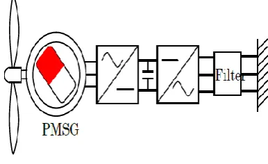
1.2 Variable Speed Wind Turbine with Permanent Magnet Synchronous Generator
This generator is connected through a back-to-back converter to the grid. This provides maximum flexibility, enabling full real and reactive power control and fault ride-through capability during voltage dips. The schematic diagram and the equivalent circuit of PMSG are shown in Figures 1.1 and 1.2, respectively. The equivalent circuit nomenclature and details can be found.
Figure1. 1: PMSG Schematic Diagram.
Figure 1.2: PMSG Equivalent Circuit 2.Solar Power
2.1 Photovoltaic Effect:
Photovoltaic (PV) is a method of generating electrical power by converting solar radiation into direct current electricity using semiconductors that exhibit the photovoltaic effect. Photovoltaic power generation employs solar panels comprising a number of cells containing a photovoltaic material. Materials presently used for photovoltaic include mono crystalline silicon, polycrystalline silicon, amorphous silicon, cadmium telluride, and copper indium selenide/sulfide.[1] Due to the growing demand for renewable energy sources, the manufacturing of solar cells and photovoltaic arrays has advanced considerably in recent years.
As of 2010, solar photovoltaic generates electricity in more than 100 countries and, while yet comprising a tiny fraction of the 4800 GW total global power-generating capacity from all sources, is the fastest growing power-generation technology in the world.
Between 2004 and 2009, Grid-connected PV capacity increased at an annual average rate of 60 percent, to some 21 GW. Such installations may be ground-mounted (and sometimes integrated with farming and grazing) or built into the roof or walls of a building, known as Building Integrated Photovoltaic or BIPV for short. Off-grid PV accounts for an additional 3–4 GW.
International Journal of Research (IJR)
e-ISSN: 2348-6848, p- ISSN: 2348-795X Volume 2, Issue 08, August 2015Available at http://internationaljournalofresearch.org
declined steadily since the first solar cells were manufactured. Net metering and financial incentives, such as preferential feed-in tariffs for solar-generated electricity; have supported solar PV installations in many countries.
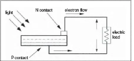
The photovoltaic effect is the generation of a voltage (or a corresponding electric current) in a material upon exposure to light. Though the photovoltaic effect is directly related to the photoelectric effect, the two processes are different and should be distinguished. In the photoelectric effect, electrons are ejected from a material's surface upon exposure to radiation of sufficient energy. The photovoltaic effect is different in that the generated electrons are transferred between different bands (i.e. from the valence to conduction bands) within the material, resulting in the buildup of a voltage between two electrodes. In most photovoltaic applications the radiation is sunlight and for this reason the devices are known as solar cells. In the case of a p-n junction solar cell, illumination of the material results in the generation of an electric current as excited electrons and the remaining holes are swept in different directions by the built-in electric field of the depletion region. The photovoltaic effect was first observed by Alexandre-Edmond Becquerel in 1839.
Fig 2.1: PV effect converts the photon energy into voltage across the pn junction
As of October 2010, the largest photovoltaic (PV) power plants in the world are the Sarnia Photovoltaic Power Plant (Canada, 80 MW), the Olmedilla Photovoltaic Park (Spain, 60 MW), the Strasskirchen Solar Park
(Germany, 54 MW), the Lieberose Photovoltaic Park (Germany, 53 MW), the Puertollano Photovoltaic Park (Spain, 50 MW), the Moura photovoltaic power station (Portugal, 46 MW), and the Waldpolenz Solar Park (Germany, 40 MW).
Applications In Buildings
In Transport
Standalone Devices
Rural Electrification
Solar roadways
Solar Power Satellites Performance
Temperature
Optimum Orientation of Solar Panels
Irradiation
Insolation
2.2 Solar Cell
A solar cell is a solid state device that converts the energy of sunlight directly into electricity by the photovoltaic effect. Assemblies of cells are used to make solar modules, also known as solar panels. The energy generated from these solar modules, referred to as solar power, is an example of solar energy.
The origin of the PV potential is the difference in the chemical potential, called the Fermi level, of the electrons in the two isolated materials. When they are joined, the junction approaches a new thermodynamic equilibrium. Such equilibrium can be achieved only when the Fermi level is equal in the two materials. This occurs by the flow of electrons from one material to the other until a voltage difference is established between them, which have a potential just equal to the initial difference of the Fermi level. This potential drives the photocurrent in the PV circuit.
International Journal of Research (IJR)
e-ISSN: 2348-6848, p- ISSN: 2348-795X Volume 2, Issue 08, August 2015Available at http://internationaljournalofresearch.org
of photovoltaic cells in producing electricity from light, though it is often used specifically to refer to the generation of electricity from sunlight.
Cells are described as photovoltaic cells when the light source is not necessarily sunlight. These are used for detecting light or other electromagnetic radiation near the visible range, for example infrared detectors), or measurement
of light intensity.
Fig 2.2: Basic construction of PV cell
The diagram above illustrates the operation of a basic photovoltaic cell, also called a solar cell. Solar cells are made of the same kinds of semiconductor materials used in microelectronics, such as silicon (melted sand) or cadmium telluride. For solar cells, a thin semiconductor wafer is specially treated to form an electric field, positive on one side and negative on the other. When light energy strikes the solar cell, electrons are knocked loose from the atoms in the semiconductor material. If electrical conductors are attached to the positive and negative sides, forming an electrical circuit, the electrons can be captured in the form of an electric current. This electricity can then be used to power a load, such as a light or a tool. Each PV cell converts about 5 to 15 percent of the sunlight that hits it into electrical current. Photovoltaic cells are modular. That is, one can be used to make a very small amount of electricity, or many can be used together to make a large amount of electricity.
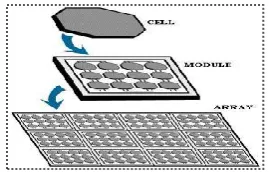
Fig 2.3:Thepv array set up
Photovoltaic cell produces only about one-half volt of electricity, cells are often mounted together in groups called modules. Each module holds about forty photovoltaic cells. By being put into modules, the current from a number of cells can be combined. PV cells can be strung together in a series of modules or strung together in a parallel placement to increase the electrical output.
When multiple PV cell modules are put together, they can form an arrangement called an array or array field. In general, the larger the area of a module or array, the more electricity that will be produced. Photovoltaic modules and arrays produce direct current (dc) electricity. They can be connected in both series and parallel electrical arrangements to produce any required voltage and current combination. 2.2.1 Types Of Photovoltaic Cells: Monocrystalline PV cell
Polycrystalline PV cell Amorphous or thin-film cell.
International Journal of Research (IJR)
e-ISSN: 2348-6848, p- ISSN: 2348-795X Volume 2, Issue 08, August 2015Available at http://internationaljournalofresearch.org
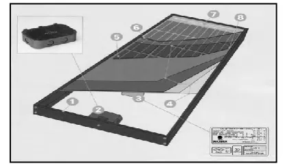
Fig 2.5: Construction of PV module: (1) frame, (2) weatherproof junction box, (3) rating
plate, (4) weather protection for 30-yr life, (5) PV cell, (6) tempered high-transmittivity cover glass, (7) outside electrical bus, (8) frame clearance. (From Solarex/BP Solar, Frederick, MD.
2.2.2 Main Operation: Solar cell works in three steps:
Photons in sunlight hit the solar panel and are absorbed by semiconducting materials, such as silicon.
Electrons (negatively charged) are knocked loose from their atoms, allowing them to flow through the material to produce electricity. Due to the special composition of solar cells, the electrons are only allowed to move in a single direction.
An array of solar cells converts solar energy into a usable amount of direct current (DC) electricity.
2.2.3 Equivalent Circuit:
Fig 2.6:PV cell equivalent circuit
The complex physics of the PV cell can be represented by the equivalent electrical circuit. The circuit parameters are as follows. The current Iat the output terminals is equal to the light-generated current IL, less the diode
current Id and the shunt-leakage current Ish. The
series resistance Rs represents the internal
resistance to the current flow, and depends on the pn junction depth, impurities, and contact resistance. The shunt resistance Rsh is inversely
related to the leakage currentto ground. In an ideal PV cell, Rs = 0 (no series loss), and
Rsh=(no leakage to ground). In a typical
high-quality 1 in.2 silicon cell, Rs varies from 0.05 to 0.10 and Rsh from 200 to 300 . The PV
conversion efficiency is sensitive to small variations in Rs, but is insensitive to variations in Rsh. A small increase in Rs can decrease the
PV output significantly. In the equivalent circuit, the current delivered to the external load equals the current IL generated by the
illumination, less the diode current Id and the shunt leakage current Ish. The open-circuit
voltage Voc of the cell is obtained when the load current is zero, i.e., when I = 0, and is given by the following:
Voc=V+IRsh
The shunt resistance (Rsh) is very large
and the series resistance (Rs) is very small. Therefore, it is common to neglect these resistances in order to simplify the solar cell model. The resultant ideal voltage-current characteristic of a photovoltaic cell is given by the relation below and illustrated by the figure above.
I=Iph-ID
I=Iph-I0 exp q V+RsI
AkBT −1 −
V+RsI
Rsh Where,
Iph = photocurrent,
ID = diode current,
I0 = saturation current,
A = ideality factor,
q = electronic charge 1.6x10⁻⁹,
kB= Boltzmann’s gas constant (1.38x10 -23),
T = cell temperature, Rs = series resistance,
International Journal of Research (IJR)
e-ISSN: 2348-6848, p- ISSN: 2348-795X Volume 2, Issue 08, August 2015Available at http://internationaljournalofresearch.org
I = cell current, V = cell voltage
The power output of a solar cell is given by PPV = VPV * IPV
Where,
IPV = Output current of solar cell (A).
VPV = Solar cell operating voltage (V).
PPV =Output power of solar cell (W).
The power-voltage (P-V) characteristic of a photovoltaic module operating at a standard irradiance of 1000 W/m2 and temperature of 25oC is shown below.
Fig 2.7: Power-Voltage (PV) Characteristic of a Photovoltaic Module.
It can be seen from the characteristics, that there is a unique point on the characteristics at which the photovoltaic power is maximum. This point is termed as the maximum power point (MPP). The power corresponding to this point is termed as power at maximum power point (Pmpp) and
the voltage as voltage at maximum power point (Vmpp). Due to high cost of solar cells, it must be
ensured that the photovoltaic array operates at all time to provide maximum power output. Hence a maximum power point tracker must be used to track the maximum power of the system. This is commonly known as maximum power point tracking (MPPT). Now if the irradiance level of the photovoltaic system is changed from the standard 1000 W/m2 to say 600 W/m2 or 400 W/m2 then the P-V characteristic will change as shown in the figure below.
Fig 2.8: Variation of P-V Characteristics of Photovoltaic Module
The above graph shows that, the maximum power of the PV system also reduces accordingly. The maximum power point tracker must now track the new maximum power point for the changed irradiance level.
Solar Trackers
A solar tracker is a generic term used to describe devices that orient various payloads toward the sun. Payloads can be photovoltaic panels, reflectors, lenses or other optical devices.
Fig 2.9: Sun-tracking actuator principle.
International Journal of Research (IJR)
e-ISSN: 2348-6848, p- ISSN: 2348-795X Volume 2, Issue 08, August 2015Available at http://internationaljournalofresearch.org
therefore must be oriented appropriately to collect energy. Tracking systems are found in all concentrator applications because systems do not produce energy unless oriented toward the sun.
Major Components Of A Solar Panel:
Glass Cover- Provides protection from the elements .Anti-Reflective Coating - Substance used to prevent the light that strikes from bouncing off the panel. .Top Negative Contact - Negative Post (Terminal, like in your battery) .N-Type Layer - Semi-conductor layer dipped in phosphorus .P-Type Layer - Semi-conductor layer dipped in boron .Bottom Positive Contact - Positive Post (Terminal, like in a battery)
2. RELATED WORK
Existing System:
2.1 Distributed Generation:
The centralized and regulated electric utilities have always been the major source of electric power engenderment and supply. However, the incrimination in demand for electric power has led to the development of distributed generation (DG) which can complement the central power by providing Adscititiously capacity to the users. These are minute engendering units which can be located at the consumer end or anywhere within the distribution system. DG can be salutary to the consumers as well as the utility. Consumers are intrigued with DG due to the sundry benefits associated with it: cost preserving during peak demand charges, higher power quality and incremented energy efficiency. The utilities can additionally benefit as it generally eliminates the cost needed for laying incipient transmission/distribution lines. Distributed generation employs alternate resources such as micro-turbines, solar photovoltaic systems, fuel cells and wind energy
systems. This thesis lays accentuation on the fuel cell technology and its integration with the utility grid.
2.2 Distributed Generation Systems
Background:
International Journal of Research (IJR)
e-ISSN: 2348-6848, p- ISSN: 2348-795X Volume 2, Issue 08, August 2015Available at http://internationaljournalofresearch.org
Fig 2.1: A large central power plant and distributed generation systems.
Recently, the use of distributed generation systems under the 500 kW level is rapidly incrementing due to technology ameliorations in minuscule engenderers, power electronics, and energy storage contrivances. Efficient clean fossil-fuels technologies such as micro-turbines, fuel cells, and environmental-amicable renewable energy technologies such as biomass, solar/photovoltaic arrays, diminutive wind turbines and hydro turbines, are growingly used for incipient distributed generation systems. These DGS are applied to a standalone , a grid-interconnected, a standby, peak shavings , a cogeneration etc. and have a lot of benefits such as environmental-amicable and modular electric generation, incremented reliability/stability, high power quality, load management, fuel flexibility, uninterruptible accommodation, cost savings, on-site generation, expandability, etc.
Fig 2.2: Operating system for DGS.
The major distributed generation technologies that will be discussed in this chapter are as follows: micro-turbines, fuel cells, wind turbines, solar/photovoltaic systems, and energy storage contrivances. Other distributed energy technologies are combustion/diesel engines. However, these technologies will not be expounded due to high emissions, high operation and maintenance costs. Therefore, emerging and renewable generation technologies are described in detail in the following.
Micro-turbines, especially the minuscule gas-fired micro-turbines in the 25-500 kW that can be mass-engendered at low cost have been more alluring due to the competitive price of natural gas, low installation and maintenance costs. It takes very clever engineering and utilization of innovative design (e.g. air bearing, recuperation) to achieve plausible efficiency and costs in machines of lower output. A immensely colossal advantage of these systems is minuscule-sized because these technologies mainly use high-speed turbines (50,000-120,000 RPM) with air foil bearings. Therefore, micro-turbines are one of the most promising of the DGS technologies for applications today. Figure 1.3 shows a block diagram of micro-turbine system that consists of air compressor, recuperator, combustor, turbine, engenderer, and a PCU (Power Conditioning Unit) and its features are summarized below.
Proposed System:
2.3 Wind power:
International Journal of Research (IJR)
e-ISSN: 2348-6848, p- ISSN: 2348-795X Volume 2, Issue 08, August 2015Available at http://internationaljournalofresearch.org
Sizably voluminous wind farms consist of hundreds of individual wind turbines which are connected to the electric power transmission network. Offshore wind is steadier and more vigorous than on land, and offshore farms have less visual impact, but construction and maintenance costs are considerably higher. Minuscule onshore wind farms provide electricity to isolated locations. Utility companies increasingly buy surplus electricity engendered by diminutive domestic wind turbines.
Wind puissance, as an alternative to fossil fuels, is plentiful, renewable, widely distributed, immaculate, engenders no greenhouse gas emissions during operation and uses little land.The effects on the environment are generally less problematic than those from other power sources. As of 2011, Denmark is engendering more than a quarter of its electricity from wind and 83 countries around the world are utilizing wind power on a commercial substratum. In 2010 wind energy engenderment was over 2.5% of total ecumenical electricity utilization, and growing rapidly at more than 25% per annum. The monetary cost per unit of energy engendered is homogeneous to the cost for incipient coal and natural gas installations.
Wind power is very consistent from year to year but has paramount variation over shorter time scales. The intermittency of wind seldom engenders quandaries when used to supply up to 20% of total electricity demand, but as the proportion increases, a desideratum to upgrade the grid, and a lowered ability to supplant conventional engenderment can occur.Power management techniques such as having excess capacity storage, geographically distributed turbines, dispatch able backing sources, storage such as pumped-storage hydroelectricity, exporting and importing power to neighbouringareas or reducing demand when
wind engenderment is low, can greatly mitigate these quandaries.In integration, weather forecasting sanctions the electricity network to be readied for the prognostic able variations in engenderment that occur.
Wind is the kinetics of air across the surface of the Earth, affected by areas of high pressure and of low pressure. The surface of the Earth is heated unevenly by the Sun, depending on factors such as the angle of incidence of the sun's rays at the surface (which differs with latitude and time of day) and whether the land is open or covered with vegetation. Withal, astronomically immense bodies of dihydrogen monoxide, such as the oceans, heat up and cool down more gradual than the land. The heat energy absorbed at the Earth's surface is transferred to the air directly above it and, as warmer air is less dense than cooler air, it elevates above the cool air to compose areas of high pressure and thus pressure differentials. The rotation of the Earth drags the atmosphere around with it causing turbulence. These effects coalesce to cause a perpetually varying pattern of winds across the surface of the Earth.
International Journal of Research (IJR)
e-ISSN: 2348-6848, p- ISSN: 2348-795X Volume 2, Issue 08, August 2015Available at http://internationaljournalofresearch.org
manner". They later estimated 80 TW. However research at Harvard University estimates 1 Watt/m2 on average and 2-10 MW/km2 capacity for astronomically immense scale wind farms, suggesting that these estimates of total ecumenical wind resources are too high by a factor.
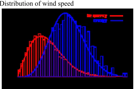
Distribution of wind speed
Fig 2.3: Illustrate Distribution of wind speed The vigor of wind varies, and an average value for a given location does not solitary designate the amount of energy a wind turbine could engender there. To assess the frequency of wind speeds at a particular location, a probability distribution function is often fit to the observed data. Different locations will have different wind speed distributions. The Weibull model proximately mirrors the authentic distribution of hourly/ten-minute wind speeds at many locations. The Weibull factor is often proximate to 2 and therefore a Rayleigh distribution can be utilized as a less precise, but simpler model.
3. IMPLEMENTATION
3.1 High altitude winds
Power generation from winds customarily emanates from winds very proximate to the surface of the earth. Winds at higher altitudes are more vigorous and more consistent, and may have an ecumenical capacity of 380 TW.Recent years have visually perceived paramount advances in technologies betokened to engender electricity from high altitude winds.
3.2Wind farms
A wind farm is a group of wind turbines in the same location utilized for engenderment of electricity. A sizably voluminous wind farm may consist of several hundred individual wind turbines distributed over an elongated area, but the land between the turbines may be utilized for agricultural or other purposes. A wind farm may withal be located offshore.
Virtually all sizably voluminous wind turbines have the same design — a horizontal axis wind turbine having an upwind rotor with three blades, affixed toa nacelle on top of a tall tubular tower. In a wind farm, individual turbines are interconnected with a medium voltage (often 34.5 kV), power accumulation system and communications network. At a substation, this medium-voltage electric current is incremented in voltage with a transformer for connection to the high voltage electric power transmission system.
3.3Phase Locked Loop
A phase-locked loop or phase lock loop (PLL) is a control system that tries to generate an output signal whose phase is related to the phase of the input "reference" signal. It is an electronic circuit consisting of a variable frequency oscillator and a phase detector that compares the phase of the signal derived from the oscillator to an input signal. The signal from the phase detector is used to control the oscillator in a feedback loop. The circuit compares the phase of the input signal with the phase of a signal derived from its output oscillator and adjusts the frequency of its oscillator to keep the phases matched.
International Journal of Research (IJR)
e-ISSN: 2348-6848, p- ISSN: 2348-795X Volume 2, Issue 08, August 2015Available at http://internationaljournalofresearch.org
can track an input frequency, or it can generate a frequency that is a multiple of the input frequency. The former property is used for demodulation, and the latter property is used for indirect frequency synthesis.
Phase-locked loops are widely used in radio, telecommunications, computers and other electronic applications. They may generate stable frequencies, recover a signal from a noisy communication channel, or distribute clock timing pulses in digital logic designs such as microprocessors. Since a single integrated circuit can provide a complete phase-locked-loop building block, the technique is widely used in modern electronic devices, with output frequencies from a fraction of a hertz up to many gigahertz
3.3.1Structure and function
Phase-locked loop mechanisms may be implemented as either analog or digital circuits. Both implementations use the same basic structure.
Block diagram of a PLL (without filter)
Both analog and digital PLL circuits include four basic elements:
Phase detector, low-pass filter
Variable frequency electronic oscillator, and
Feedback path (which may include a frequency divider).
3.3.2 Variations
There are several variations of PLLs. Some terms that are used are analog phase-locked loop (APLL) also referred to as a linear phase-locked loop (LPLL), digital phase-locked loop (DPLL), all digital phase-locked loop
(ADPLL), and software phase-locked loop (SPLL). An analog PLL uses components that have analog (linear) outputs A digital PLL implies that at least some of the phase-locked loop components are digital. There may be digital phase detector or a digital frequency divider, for example, but the VCO may be analog.
Digital PLLs use digital filtering techniques to process the baseband error signal. A time-to-digital converter is used in place of the analog phase detector to digitize the time arrival difference between the NCO output and a reference signal. The resulting digital signal is filtered using signal processing techniques before finally being converted back into the analog domain (via a digital-to-analog converter) to provide a steering signal to the analog VCO.
The term ADPLL uses all digital components. In place of a voltage-controlled oscillator (VCO), a DPLL may use a local reference clock and a variable dividing counter under digital control to create the equivalent oscillator function. The SPLL is an ADPLL implemented in software. The implementation may be done on a digital signal processor or on a general purpose computer. Performance parameters
Loop bandwidth Lock range Capture range Transient response Steady-state errors
3.3.3 Spread spectrum
International Journal of Research (IJR)
e-ISSN: 2348-6848, p- ISSN: 2348-795X Volume 2, Issue 08, August 2015Available at http://internationaljournalofresearch.org
interference caused by it. The emitted noise generally appears at sharp spectral peaks (usually at the operating frequency of the device, and a few harmonics). A system designer can use a spread-spectrum PLL to reduce interference with high-Q receivers by spreading the energy over a larger portion of the spectrum. For example, by changing the operating frequency up and down by a small amount (about 1%), a device running at hundreds of megahertz can spread its interference evenly over a few megahertz of spectrum, which drastically reduces the amount of noise seen on broadcast FM radio channels, which have a bandwidth of several tens of kilohertz.
Typically, the reference clock enters the chip and drives a phase locked loop (PLL), which then drives the system's clock distribution. The clock distribution is usually balanced so that the clock arrives at every endpoint simultaneously. One of those endpoints is the PLL's feedback input. The function of the PLL is to compare the distributed clock to the incoming reference clock, and vary the phase and frequency of its output until the reference and feedback clocks are phase and frequency matched.
PLLs are ubiquitous—they tune clocks in systems several feet across, as well as clocks in small portions of individual chips. Sometimes the reference clock may not actually be a pure clock at all, but rather a data stream with enough transitions that the PLL is able to recover a regular clock from that stream. Sometimes the reference clock is the same frequency as the clock driven through the clock distribution,
other times the distributed clock may be some rational multiple of the reference.
3.3.4 Feedback path and optional divider An Example Digital Divider (by 4) for use in the Feedback Path of a Multiplying PLL
PLLs may include a divider between the oscillator and the feedback input to the phase detector to produce a frequency synthesizer. A programmable divider is particularly useful in radio transmitter applications, since a large number of transmit frequencies can be produced from a single stable, accurate, but expensive, quartz crystal–controlled reference oscillator.
Some PLLs also include a divider between the reference clock and the reference input to the phase detector. If the divider in the feedback path divides by N and the reference input divider divides by M, it allows the PLL to multiply the reference frequency by N / M. It might seem simpler to just feed the PLL a lower frequency, but in some cases the reference frequency may be constrained by other issues, and then the reference divider is useful.
Frequency multiplication in a sense can also be attained by locking the PLL to the 'N'th harmonic of the signal.
International Journal of Research (IJR)
e-ISSN: 2348-6848, p- ISSN: 2348-795X Volume 2, Issue 08, August 2015Available at http://internationaljournalofresearch.org
(rather than a multiple) of the reference frequency. A mixer can translate the VCO frequency by a fixed offset. It may also be a combination of these. An example being a divider following a mixer; this allows the divider to operate at a much lower frequency than the VCO without a loss in loop gain
3.4 Magnetism and Electromagnetism:
Certain materials found in nature exhibit a propensity to magnetize or repeal each other. These materials, called magnets, are additionally called ferromagnetic because they include the element iron as one of their constituting elements.
Magnets always have two poles: one called north; the other called south. Two north poles always repel each other, as do two south poles. However, north and south poles always magnetize each other. A magnetic field is defined as a physical field established between to poles. Its intensity and direction determine the forces of magnetization or repulsion subsisting between the two magnets. Figures 6 and 7 are typical representations of two interacting magnetic poles, and the magnetic field established between them. Magnets are found in nature in all sorts of shapes and chemical constitution. Magnets utilized in industry are artificially made. Magnets that sustain their magnetism for long periods of time are denominated ―permanent magnets.‖ These are widely utilized in several types of electric rotating machines, including synchronous machines. However, due to mechanical, as well as operational reasons, perpetual magnets in synchronous machines are restricted to those with ratings much lower than sizably voluminous turbine-driven engenderers, which is the subject of this book. Turbine-driven engenderers (for short: turbogenerators) capitalize on the fact that magnetic fields can be engendered by the flow of electric currents in conductors. Optically discern Figure 8.
Fig 3.3: Schematic representation of two magnetic poles of opposite polarity, and the magnetic field between them shown as ―lines of force.‖
Fig 3.4: Schematic representation of two north poles, and the magnetic field between them. South poles will create similar field patterns, but the lines of force will point toward the poles.
Fig 3.4: Schematic representation of a magnetic field created by the flow of current in a conductor.
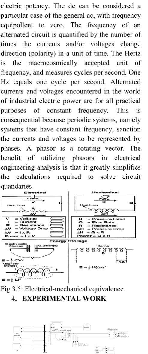
3.5 Electrical—Mechanical Equivalence:
There is a fascinating equipollence between the sundry parameters describing electrical and mechanical forms of energy. People with either electrical or mechanical backgrounds find this equipollence subsidiary to the construal of the physical process in either form of energy. Figure 1.6 describes the sundry forms of electrical-mechanical equipollence.
3.6 Alternated Circuits (AC)
International Journal of Research (IJR)
e-ISSN: 2348-6848, p- ISSN: 2348-795X Volume 2, Issue 08, August 2015Available at http://internationaljournalofresearch.org
electric potency. The dc can be considered a particular case of the general ac, with frequency equipollent to zero. The frequency of an alternated circuit is quantified by the number of times the currents and/or voltages change direction (polarity) in a unit of time. The Hertz is the macrocosmically accepted unit of frequency, and measures cycles per second. One Hz equals one cycle per second. Alternated currents and voltages encountered in the world of industrial electric power are for all practical purposes of constant frequency. This is consequential because periodic systems, namely systems that have constant frequency, sanction the currents and voltages to be represented by phases. A phasor is a rotating vector. The benefit of utilizing phasors in electrical engineering analysis is that it greatly simplifies the calculations required to solve circuit quandaries
Fig 3.5: Electrical-mechanical equivalence.
4. EXPERIMENTAL WORK
4.1 IntegratedHybrid Power Optimizer System
Fig4.2: Source Voltage,Source Current,DC Voltage from Grid.
Fig4.3: Solar DC Output Voltage to Grid
Fig4.4: Battery Output Voltage to Grid
International Journal of Research (IJR)
e-ISSN: 2348-6848, p- ISSN: 2348-795X Volume 2, Issue 08, August 2015Available at http://internationaljournalofresearch.org
5. CONCLUSION
This paper described the modeling of Wind Energy Conversion System, Solar Grid System & Battery connected to Grid. Itconsistof wind turbine, PMSG, Solar Panel, Battery, rectifier, inverter and grid model. The model has been implemented in MATLAB/ SIMULINK. Simulation results show the steady state performance of the wind energy conversion system (WECS)& Solar Energy Conversion System.
6.REFERENCES
[1] S. Samanvorakij, P. Kumkratug ―Modeling and Simulation PMSG based on Wind Energy Conversion System in MATLAB/SIMULINK‖ Proc. of the Second Intl. Conf. on Advances in Electronics and Electrical Engineering — AEEE 2013
[2] M.Ying, G.Li, M.zhou, and C.Zhao,"Modeling of the wind turbine with a permanent magnet synchronous generator for integration," IEEE, pp.1-6, 2007.ISBN1-4244-1298-6
[3] SumanNath, SomnathRana ―The Modeling and Simulation of Wind Energy Based Power System using MATLAB‖ International Journal of Power System Operation and Energy Management, ISSN (PRINT): 2231–4407, Volume-1, Issue-2, 2011
[4] A. B. Cultura and Z. M. Salameh, ―Modeling and Simulation of a Wind Turbine-Generator System‖ 978-1-4577-1002-5/11©2011 IEEE
[5] S. Saikuma, S. Saravanan, and R. V. Sandip, ―Modeling and Control of a Wind Turbine using Permanent Magnet Synchronous Generator‖, IJEST, Vol3, no., pp.2377-2384, 3 March 2011.
[6] ―Three-Phase Full wave Controlled Converters (Controlled rectifier)‖ University of Technology Laser and Optoelectronics Engineering Department Laser Engineering Branch Power electronics 2011-2012
[7] Y. Fang and X. Ma, ―A novel PVmicroinverter with coupled inductors and double-boost topology,‖ IEEE Trans. Power Electron., vol. 25, no. 12,pp. 3139–3147, Dec. 2010.
[8] A. Ch. Kyritsis, E. C. Tatakis, and N. P. Papanikolaou, ―Optimum design of the current-source fly back inverter for decentralized gridconnected photovoltaic systems,‖ IEEE Trans. Energy Convers., vol. 23, no. 1, pp. 281– 293, Mar. 2008.
[9] P. Tsao, ―Simulation of PV systems with power optimizers and distributed power electronics,‖ in Proc. IEEE Photo volt. Spec. Conf., Jun. 2010,pp. 389–393.
[10] D. D.-C. Lu and V. G. Agelidis, ―Photovoltaic-battery-powered DC bus system for common portable electronic devices,‖ IEEE Trans. PowerElectron., vol. 24, no. 3, pp. 849– 855, Feb. 2009.