Integrating Renewable Sources for Grid Connected
Distributed Generation System Using Fuzzy Controller Fed
PMSM Drive
NARENDRUNI ANIL M-tech Student Scholar
Department of Electrical & Electronics Engineering, Scient institute of technology;
Ranga Reddy (Dt); Telangana, India. Email:[email protected]
K.SREEPAL REDDY Associate Professor
Department of Electrical & Electronics Engineering, Scient institute of technology;
Ranga Reddy(Dt); Telangana, India. Email:sreepalpid@OM
Abstract— this model proposes a method for in use a grid connected hybrid system. This system collected of a Photovoltaic (PV) array and a Proton exchange membrane fuel cell (PEMFC) is considered. As the variation happen in temperature and irradiation during power delivery to load, Photo voltaic (PV) system becomes uncontrollable. In organization with PEMFC, the hybrid system output power become convenient. Two operation modes are the unit-power control (UPC) mode and the feeder-flow control (FFC) mode, can be applied to the hybrid system. All MPPT methods follow the same goal that is maximizing the PV system output power by tracking the maximum power on every operating condition. Maximum power point tracking technique (Incremental conductance) for photovoltaic systems was introduced to maximize the produced energy. The organization of two control modes, organization of the PV array and the PEMFC in the hybrid system, and determination of orientation parameters are presented. The proposal operating approach systems with a flexible operation mode change always operate the PV array at maximum output power and the PEMFC in its high efficiency performance band. Also thus improving the presentation of system operation, enhancing system stability, and reducing the number of operating mode changes. The proposed concept can be implemented to fuzzy controlled grid connected hybrid PV/PEMFC/Battery using PMSM drive applications using Matlab/Simulink software.
Index Terms—Fuel cell, Battery, Distributed generation,
Photovoltaic Cell, Fuzzy Control.
I. INTRODUCTION
The penetration level of green and renewable energy sources/distributed generation units are expected to grow in the near future as there is a probability of rundown conventional fuels for power generation. The distributed generation is classified as renewable and non-renewable. The distributed generation sources such as Fuel cells, Wind and Solar energy are increasing daily due to increase in demand for electrical power [1]. These energy sources are environmental friendly, reduces transmission and distribution losses, peak load shaving, can be used as backup sources and etc. Fuel cell is a promising device as it is efficient, modular and can be placed at any site for improving system efficiency [2] but it has slow start-up response. Solar energy is an important renewable energy source [3] but the intermittent nature of this technology is a major issue. The availability of
on the loads of the systems. This technology can be labeled as intermittent and normally PV array uses a Maximum Power Point Tracking (MPPT) technique to continuously deliver the highest power to the load when there are variations in irradiation and temperature [4]. Because of the intermittent nature of PV array it becomes an uncontrollable source. In order to overcome the drawbacks with the slow start-up of fuel cells and intermittent nature of PV cell a fuzzy controlled grid connected hybrid photovoltaic and proton exchange membrane fuel cell distributed generation system with battery as energy storage is proposed in this paper
II. SYSTEM MODELING
Fig-1 Block Diagram of Grid connected Hybrid system
The grid connected hybrid system consists of a PV/PEMFC/Battery hybrid source with the main grid connecting loads at the Point of Common Coupling (PCC) as shown in Figure.1. The PV/PEMFC/Battery and the dc–dc converters are connected on the common DC bus which is coupled at the dc side of a dc/ac inverter.
(i)Proton Exchange Membrane Fuel Cell Model
(1)
Where ENerst is the “thermodynamic potential” of Nerst, which represents the reversible (or open-circuit) voltage of
the fuel cell The performance of the fuel cell is affected by many parameters and one important parameter is reactant
utilization, Uf [6] and is given by equation (2)
(2)
The Nernst's equation and ohm's law determine the average voltage magnitude of the fuel cell stack and is
given by
equation (3)
(3)
where
N0 is the number of fuel cells connected in series E0 is the reaction free energy voltage
R is the universal gas constant T is the temperature
If0 is the fuel cell stack current
PH2, PH2O, and PO2 are the partial pressures of hydrogen, water and oxygen respectively.
q represents the molar flow Kr is the Constant
(4)
(5)
(6)
(ii). PV Model
The equivalent circuit shown in Fig (2) is a one diode model of a solar cell which consists of a diode and a current
source connected in parallel with a series resistance Rs. The current source produces the photocurrent Iph, which is directly proportional to solar irradiance G. The two key parameters often used to characterize a PV cell are it‟s short circuit current and its open circuit voltage which are provided by the manufacturer‟s data sheet.
Fig.2. Equivalent solar cell model with Rs In the literature many MPPT techniques are available such as incremental conductance (INC), constant voltage (CV),
and perturbation and observation (P&O). The P&O method has been widely used because of its simple feedback structure and fewer measured parameters. The panel voltage is deliberately perturbed (increased or decreased) then the power is compared to the power obtained before to disturbance. Specifically, if the power panel is increased due to the disturbance, the following disturbance will be made in the same direction and if the power decreases, the new perturbation is made in the opposite direction. But the demerit with P & O is the output power is oscillating in nature. Because of this reason we use the Fuzzy MPPT technique to deliver the maximum power and to eliminate perturbations in the output power.
Fuzzy MPPT Control
The inputs to the fuzzy MPPT control can be measured or computed from the voltage and current of solar panel. The control rules are indicated in [4]with ¨Ppv and ¨Vpv as inputs and ¨Vpvref as the output. The membership functions of input and output Variables in which membership functions of input variables ¨Ppv and ¨Vpv are triangular and has seven fuzzy subsets. Seven fuzzy subsets are considered for membership functions of the output variable ¨V pvref. These input and output variables are expressed in terms of linguistic variables (such as BN (big negative), MN (Medium negative), SN (small negative), Z (zero), SP (small positive), MP (medium positive), and BP (big positive).
(iii). Battery Modeling
battery energy storage is combined with hybrid PV/PEMFC distributed generation system. The battery model considered in this paper is shown in fig.3. The battery model used is based on voltage model proposed by Shepherd [4].
Fig. 3. Battery Model
(iv). DC/DC Boost Converter Model
While connecting a fuel cell/ PV array to the grid it is necessary to boost the voltage. The boost converter shown in fig.4 is used for this purpose.
Fig. 4. DC-DC Converter Model
The boost converter shown in fig.4 consists of one switching device that enables it to turn on and off depending on the applied gate signal D. The gate signal for the GTO can be obtained by using fuzzy controller.
(v). DC/AC Inverter Model
The dynamic model of the voltage source inverter (VSI) is used. The DC/AC inverter is shown in fig.5. To eliminate
the harmonics filters are used in between grid and the inverter. The dynamic model of the VSC inverter is represented in [6]
Fig.5. DC/ AC Three Phase Inverter
III. POWER CONTROL STRATEGIES OF HYBRID SYSTEM
The power balance must always be controlled from sources to AC bus and to/from storage devices satisfying
active and reactive power demand by the load. The equation (12) expresses the power balance equation that should be satisfied both at the DC-link and at the Point of Common Coupling (PCC).
(7)
In this paper, Pload and Qload are made equal to Pref and Qref so that the hybrid power system output follows the load demand under normal loading conditions and Pgrid and Qgrid are zero. According to the control strategy proposed in this paper whenever the load exceeds the Pdg the excess load is supplied by the grid
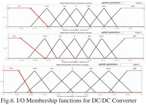
(A) DC/DC Converter Controller using Fuzzy Logic
The unregulated dc output voltage of the fuel cell is fed to the dc/dc boost converter. The voltage is boosted depending on the duty ratio. The duty ratio is controlled by the logic controller. The input to the fuzzy logic controller is the voltage error (reference-generated) and the change in the voltage error. The fuzzy controller then generates control signal which is fed to the PWM signal generator. The boost converter generates the output voltage [5]. The membership functions for the duty ratio control of DC/DC converter is shown in fig.6 with seven linguistic variables such as, negative big, negative medium, negative small, zero, positive small, positive medium & positive big.
Fig.6. I/O Membership functions for DC/DC Converter
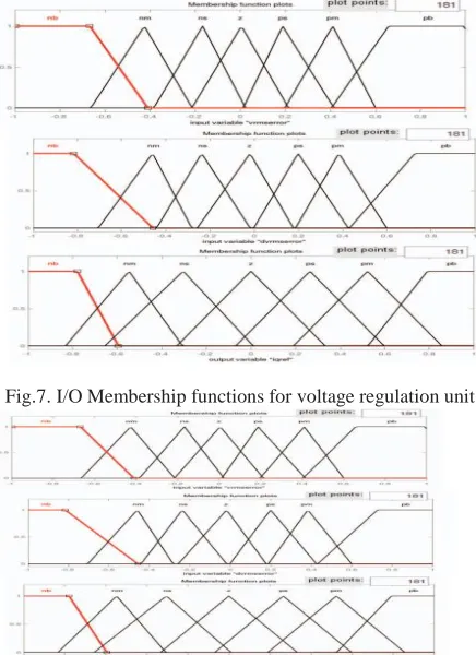
(B) DC/AC Converter Controller using Fuzzy Logic
fuzzy controller. For both the active power control and voltage regulation unit seven linguistic variables such as negative big, negative medium, negative small, zero, positive small, positive medium & positive big. The I/O membership functions are shown in fig.7 & fig 8.
Fig.7. I/O Membership functions for voltage regulation unit
Fig.8. I/O Membership functions for voltage regulation unit
IV. PERMANENT MAGNET SYNCHRONOUS MACHINE
A synchronous machine is an ac rotating machine whose speed under steady state condition is proportional to the frequency of the current in its armature. Figure 4 indicates the PMSM Cylindrical rotor and Salient rotor structures. The magnetic field created by the armature currents rotates at the same speed as that created by the field current on the rotor, which is rotating at the synchronous speed, and a steady torque results. Synchronous machines are commonly used as generators especially for large power systems, such as turbine generators and hydroelectric generators in the grid power supply. Because the rotor speed is proportional to the frequency of excitation, synchronous motors can be used in situations where constant speed drive is required. Since the reactive power generated by a synchronous machine can be adjusted by controlling the magnitude of the rotor
field current, unloaded synchronous machines are also often installed in power systems solely for power factor correction. The armature winding of a conventional synchronous machine is almost invariably on the stator and is usually a three phase winding. The field winding is usually on rotor and excited by dc current, or permanent magnets. The dc power supply required for excitation usually is supplied through a dc generator known as exciter, machine which is often mounted on the same shaft as the synchronous.
Fig.9. Cylindrical rotor and Salient rotor structures.
V SIMULATION RESULTS
Fig 10 Matlab/simulation circuit of Grid connected Hybrid system with fuzzy
Fig 11 Simulation Results of Voltage at PCC
Fig 12 Simulation Results of Currents at PCC
Fig 13 Simulation Results of Hybrid Active Power & Reference Active Power
Fig 15 Matlab/simulation circuit of Grid connected Hybrid system with PMSM drive
Fig 16 simulation wave form of Grid connected Hybrid system PMSM drive with current, emf, torque and speed
V CONCLUSION
The proposed work deals with the power control strategies of a fuzzy controlled grid connected hybrid photovoltaic/ proton exchange membrane fuel cell distributed generation system with battery storage. The battery responds quickly to load transients leaving the fuel cell to respond slowly. The proposed with PMSM Drive analysis of current, speed and torque can be observed using of MATLAB/SIMULINK
REFERENCES
[1] Edward J. Coster, Johanna M. A. Myrzik, Bas Kruimer, Wil L. Kling, " Integration issues of distributed generation in distribution grids" proceedinds of IEEE, January 2011
[2] Djamila Rekioua and Ernest Matagne, “Optimization of Photovoltaic Power Systems”, Springers, 2012 [3] M. Hashem Nehrir and C. Wang, “Modelling and Control of Fuel Cells”, Wiley, 2009
[4] C. M. Shepherd, "Design of primary and secondary cells II .An equation describing battery discharge", J. Electrochem. Soc. 112, 657 (1965).
[5] A. Hajizadeh and M. Aliakbar-Golkar “Fuzzy Control of Fuel Cell Distributed Generation Systems” Iranian Journal of Electrical & Electronic Engineering, Vol. 3, Nos. 1 & 2, Jan. 2007.
[6] Golkar M. A. and Hajizadeh A., “Intelligent power management strategy of hybrid distributed generation system,”.Journal of Electrical Power and Energy Systems, June 2007
[7] Amin Hajizadeh, Samson G. Tesfahunegn, and Tore M. Undeland, " Intelligent control of hybrid photo voltaic/fuel cell/energy storage power generation system" J. Renewable Sustainable Energy 3, 043112 (2011); doi: 10.1063/1.3618743
[8] Loc Nguyen Khanh, Jae-Jin Seo, Yun-Seong Kim, and Dong-Jun Won,“Power Management Strategies for a Grid connected PV-FC HybridSystem” IEEE transactions on Power Delivery, July 2010
[9] T. Praveen Kumar, N. Subrahmanyam, M. Sydulu “Control strategies for a grid connected hybrid energy
systems” IEEE TENCON Spring 2013.
[10] F. Katiraei and M. R. Iravani, “Power management strategies for a microgrid with multiple distributed generation units,” IEEE Trans. PowerSyst., vol. 21, no. 4, pp. 1821–1831, Nov. 2006.
[11] Amin Ghazanfari, Mohsen Hamzeh, Hossein Mokhtari, and Houshang Karimi, "Active Power Management of Multihybrid Fuel Cell/Supercapacitor Power Conversion System in a Medium Voltage
Microgrid" IEEE Transactions on Smart Grid, December 2010
[12] JIANG Z., GAO L., DOUGAL R.A.: „Flexible multiobjective control of power converter in active hybrid fuel cell/ battery power sources‟, IEEE Trans. Power Electron., 2005,
[13] El-Samadhi I. and El-Satiny E., “The Effect of DG on Power Quality in a Deregulated Environment,” in Proc. IEEE PES General Meeting, Jun. 2005. [14] Tanrioven M, Alam MS. "Modeling, control and power quality evaluation of a PEM fuel cell based power supply system for residential use". In: Proceedings of the 39th IAS annual meeting, vol. 4; 2004. p. 2808–14. [15] El-Shater TF, Eskander M, El-Hagry M. Hybrid pv/fuel cell system design and simulation. In: 36th Intersociety energy conversion engineering conference, Savannah, GA; July 29–August 2, 2001.
Author’s Profile:
NARENDRUNI ANIL received B-tech from VGNT(JNTUH) College of Engineering in the year 2014 and now pursuing M.Tech in the stream of power Electronics at Scient institute of technology.