The data acquisition system of the NA62 experiment at
CERN
MarcoBoretto1∗, on behalf of the NA62 Collaboration
1Dipartimento di Fisica Sperimentale dell’Università e Sezione dell’INFN di Torino, I-10125 Torino, Italy
Abstract. The aim of the NA62 experiment is to study the extreme rare kaon decayK+ → π+ν¯νand to measure its branching ratio with a 10% accuracy.
In order to do so, a very high intensity beam from the CERN SPS is used to produce charged kaons whose decay products are detected by many detectors installed along a 60 m decay region. The NA62 Data Acquisition system (DAQ) exploits a multi-level trigger system; following a Level0 (L0) trigger decision, 1 MHz data rate from about 60 sources is read by a PC-farm, the partial event is built and then passed through a series of Level1 (L1) algorithms to further re-duce the trigger rate. Events passing this level are completed with the missing, larger, data sources (∼400 sources) at the rate of 100 KHz. The DAQ is built around a high performance ethernet network interconnecting the detectors to a farm of 30 servers. After an overall description of the system design and the main implementation choices that allowed to reach the required performance and functionality, this paper describes the overall behaviour of the DAQ in the 2017 data taking period. It then concludes with an outlook of possible improve-ments and upgrades that may be applied to the system in the future.
1 Introduction
The NA62 experimental apparatus [1], located at the CERN Super Proton Synchrotron (SPS), has the main goal to measure the branching ratio of theK+→π+νν¯decay with 10% precision.
This process is extremely rare, with an estimated branching ratio of∼10−10[2]. The search for this process requires a high intensity kaon beam to collect sizable signal event samples, about 1013 kaon decays have to be collected over the data taking period. For that reason the Trigger and the Data Acquisition (TDAQ) chain requires a careful design in order to guarantee a high acceptance for the signal events, while keeping a high rejection of the background.
1.1 The NA62 kaon beam
The kaon beam is produced by impinging the 400 GeV primary proton beam from SPS on a beryllium target. After the collision a 75 GeV beam composed ofπ+,K+ and protons is
selected. The delivery of the beam follows the SPS spill cycle, it can be imagined like a periodic waveform in which the amplitude alternates at a steady frequency between 0 and the maximum value. The cycle followed by the SPS delivers 4.8 seconds of beam, called burst.
Bursts can be spaced by∼40 s or∼9.6 s depending on the SPS cycle. This break is exploited
by the DAQ system to recover the initial state and be ready for the next burst. During 2017 the beam was operating at 60% of the nominal intensity.
2 The NA62 trigger and DAQ systems
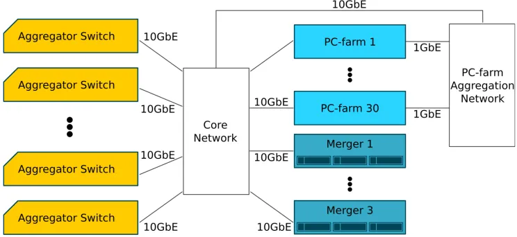
The main DAQ infrastructure (Figure 1) is composed of a cluster of 30 servers (PC-farm) and 3 servers (Mergers). The Mergers collect the output from the PC-farm and prepare it for transfer to the CERN permanent storage in the computer center.
Each PC-farm node has 2 CPU sockets with eight double threaded cores (2.7 GHz) and 64 GB of RAM. A PC-farm node is equipped with 2 Network Interface Cards (NIC), one interface is 10 GbE and is used to receive data from the detectors, and the second is a 1 GbE NIC used to send the selected data to the Mergers. Each Merger has∼15 TB RAID 5 storage and 2 CPU sockets with eight double threaded cores (2.9 GHz). The Mergers are connected to the network with a 10 GbE link and their 44 TB total storage capacity is capable to store the raw data up to∼2.5 days. The operating system chosen for all the DAQ servers is the CentOS7 (CC7) distribution provided by CERN [3]. The DAQ reads the inputs generated by several detectors. Each detector is composed by a variable number of readout boards based on FPGAs. The amount of boards per detector is given in table 1 and table 2. NA62 relies on a multi-stage trigger system composed by the L0 and the High Level Triggers (HLT). The HLT is divided in two levels (L1 and L2).
During the design process of NA62 the maximum L0 and L1 trigger rate has been esti-mated to be∼1 MHz and∼100 KHz respectively. A further reduction of a factor 10 should be achieved by the L2 trigger in order to have final rate of events of the order of 10KHz. With those values in mind the DAQ was estimated to produce at most 3 GB per second.
Figure 1. The scheme of the NA62 DAQ infrastructure. The Aggregator Switches distribute the data generated by the detectors during a burst to the entire PC-farm cluster. The output of the PC-farm is then conveyed by the PC-farm Aggregation Network and then routed to one of the 3 Mergers.
2.1 The L0 trigger
Bursts can be spaced by∼40 s or∼9.6 s depending on the SPS cycle. This break is exploited
by the DAQ system to recover the initial state and be ready for the next burst. During 2017 the beam was operating at 60% of the nominal intensity.
2 The NA62 trigger and DAQ systems
The main DAQ infrastructure (Figure 1) is composed of a cluster of 30 servers (PC-farm) and 3 servers (Mergers). The Mergers collect the output from the PC-farm and prepare it for transfer to the CERN permanent storage in the computer center.
Each PC-farm node has 2 CPU sockets with eight double threaded cores (2.7 GHz) and 64 GB of RAM. A PC-farm node is equipped with 2 Network Interface Cards (NIC), one interface is 10 GbE and is used to receive data from the detectors, and the second is a 1 GbE NIC used to send the selected data to the Mergers. Each Merger has∼15 TB RAID 5 storage and 2 CPU sockets with eight double threaded cores (2.9 GHz). The Mergers are connected to the network with a 10 GbE link and their 44 TB total storage capacity is capable to store the raw data up to∼2.5 days. The operating system chosen for all the DAQ servers is the CentOS7 (CC7) distribution provided by CERN [3]. The DAQ reads the inputs generated by several detectors. Each detector is composed by a variable number of readout boards based on FPGAs. The amount of boards per detector is given in table 1 and table 2. NA62 relies on a multi-stage trigger system composed by the L0 and the High Level Triggers (HLT). The HLT is divided in two levels (L1 and L2).
During the design process of NA62 the maximum L0 and L1 trigger rate has been esti-mated to be∼1 MHz and∼100 KHz respectively. A further reduction of a factor 10 should be achieved by the L2 trigger in order to have final rate of events of the order of 10KHz. With those values in mind the DAQ was estimated to produce at most 3 GB per second.
Figure 1. The scheme of the NA62 DAQ infrastructure. The Aggregator Switches distribute the data generated by the detectors during a burst to the entire PC-farm cluster. The output of the PC-farm is then conveyed by the PC-farm Aggregation Network and then routed to one of the 3 Mergers.
2.1 The L0 trigger
The L0 is a hardware trigger, based on the input of a subset of detectors: CHOD, RICH, MUV and LKr. During a burst, each of those detectors contributes with data, called trigger
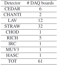
Table 1.Number of DAQ boards per L0 detector.
Detector # DAQ boards
CEDAR 6 CHANTI 2 LAV 12 STRAW 32 CHOD 1 RICH 5 IRC 1 MUV3 1 HASC 1 TOT 61
Table 2.Number of DAQ boards per L1 detector.
Detector # DAQ boards
GTK 6
LKr 432
MUV1 6
MUV2 4
TOT 448
primitives, that allow L0 to form a decision. The primitives contain the detected activity characteristics and the time of occurrence. Primitives are sent via UDP packets to the L0 Trigger Processor (L0TP) [4], which can process data coming from a maximum of seven different sources. Up to 10 MHz of primitives per detector can be handled by the system. The L0 trigger is configurable: in standard data taking conditions and beam intensity it generates about 2.3 M triggers per burst.
After a positive response from L0, data are read out from the 61 DAQ boards and sent to the PC-farm using the UDP protocol. Data from multiple events are stored in a UDP packet called MEP (Multi Event Packet), with a programmable packing factor. The NA62 readout packs together up to 8 events before sending a UDP packet to the PC-farm.
The UDP protocol has been chosen over the TCP protocol due to the simplicity of imple-mentation in the front-end FPGAs. UDP (contrary to TCP) does not implement a flow control and just needs a source and destination port for the packets, without any acknowledgement or handshake: this eliminates all issues of communication establishment, at the cost of having to deal with data loss in case of congestion. To distribute the MEPs generated by each detector a round-robin scheduling on all the PC-farm nodes is performed.
2.2 The network
The components of the NA62 network can be grouped in 3 units: Aggregator Switches, Core Network and PC-farm Aggregation Network.
The Aggregator Switches are the first element of the network chain, they collect the output sent by the detectors on the 1 GbE link and route it to the Core Network through 10 GbE optical links. The number of Aggregator Switches per detector depends on the number of sources to read.
to be sent to the 40 GbE router and routed to the proper destination. The Core Network can host up to 192 10 GbE links.
The PC-farm Aggregation Network is composed of a 1-10 GbE switch that collects the output from the 30 PC-farm 1 GbE NIC. The 10 GbE switch link is then connected to the Core Network.
Figure 2.The scheme of the NA62 Core Network. The PC-farm and detectors are connected to the four Brocade ICX 7750-48F (10-40 GbE routers) which in turn are connected to the Brocade ICX 7750-26Q router (40 GbE router) [5].
2.3 PC-farm cluster
The NA62 data acquisition software is deployed on a cluster of 30 servers and is responsible of the following functions:
• build the L1 event;
• execute the HLT algorithms;
• send the request to complete the L2 event; • build the L2 event;
• serialize the complete event.
2.3.1 PC-farm Software
The PC-farm software [6], also called DAQ software, is multi-threaded and written in C++11 [7]. The DAQ software, thanks to the round-robin scheduling, has to handle 1/30 of the MEPs generated during the burst. During the PC-farm start-up a set of initialized events called Event Pool, capable to accommodate up to 200 K events, is preallocated. The PC-farm cluster should be able to collect all the∼2.3 M event triggered by the L0. This corresponds to∼120 K MEPs per second per node.
To achieve the highest efficiency in collecting the UDP packets the DAQ software exploits PF_RING [8]: a library able to access the received packets directly from the NIC. To use this feature, the kernel network driver is replaced by the PF_RING one. PF_RING allows to scatter the incoming packets on many buffers in order to deliver them to different consumers
on the application side. A pool composed by 6 threads is continuously collecting the packets from the 10 GbE NIC on the 6 PF_RING buffers. Using the PF_RING non standard network stack means that many operations, usually handled by the kernel, need to be managed on the application side. For that reason the PC-farm software is also taking care of responding to ARP requests and to reassemble packets subjected to IP fragmentation. Furthermore the PC-farm software equipped with PF_RING has an exclusive usage of the 10 GbE NIC. Any other service that exploit the network connectivity must use the 1 GbE NIC.
Packets are then aggregated and delivered to a task manager which, after some checksum controls, assigns each fragment carried by the MEP to the corresponding event in the Event Pool. The Event Pool stores the pointers of the fragments arrived from the network that compose a physics event. This process is also called event building. There are two kinds of event building:
• The L1 event building produces the so-called L1 Event composed by the L0 detectors. • The L2 event building produces the so-called L2 Event that adds the L1 fragments to the
L1 Event.
The L1 Event for a specific event is considered complete once all the sources composing the L0 detectors have been received by the DAQ software. At this point the L1 trigger algo-rithms [9] can be run and the trigger decision evaluated. Each algorithm exploits information from individual detectors. The following L1 trigger algorithms were deployed in 2017: • The KTAG L1 trigger uses the KTAG sector-multiplicity to positively identify a kaon and
reject non-related accidental L0 triggers.
• The LAV L1 trigger uses a hit-multiplicity cut in eleven of the twelve LAV stations. It aims to reduce the background by identifying photons emitted at large angles. A cut requiring no more than two hits was applied to the events satisfying the L0 trigger.
• The STRAW L1 trigger reconstructs particle tracks by performing a two-dimensional Hough transform and a crude momentum evaluation. The number of tracks and the mo-mentum are used to evaluate the trigger decision according to the physics mask triggered by the L0.
The typical amount of events passing the L1 algorithms is∼250 K per burst. If the verdict from the L1 trigger algorithms is positive, the missing part of the event has to be requested from all the L1 sources. The event IDs to be requested are packed together in a Multiple Request Packet (MRP) and sent via a UDP packet through the 10 GbE interface. It is impor-tant to mention that this is the only traffic directed from the PC-farm to the detectors. Data are read out from 448 DAQ boards of the L1 detectors and sent to the PC-farm through the Aggregation Switches and the Core Network. The L1 DAQ boards are not packing multiple events together, each event fragment is shipped alone in the UDP packet. It is estimated that ∼23 M UDP packets per second are generated to complete all the L2 Events. To collect UDP packets generated from L0 and L1 detectors each PC-farm node has to handle a packet rate of about∼900 KHz.
The acquisition process of the L1 sources in the PC-farm software is exactly the same as described for building the L1 Event. With the complete event it is possible to execute additional algorithms to further reduce the PC-farm output. The software is set up to host them, although no algorithms were applied. Trigger algorithms combining information from several detectors are foreseen to be deployed in the future.
memory cannot be freed right away, other event fragments carried by the MEP may be still needed to complete other events. The PC-farm output is sent through the 1 GbE NIC with TCP packets to the PC-farm Aggregation Network that routes the packets back to the Core Network. The choice to use the 1 GbE port rather than the 10 GbE has been driven by the fact that it is extremely complex to implement the TCP protocol over PF_RING. Six seconds after the end of the burst the PC-farm software performs a cleanup of the Event Pool, incomplete events are deleted. After this operation the PC-farm cluster is ready to receive the subsequent burst.
2.4 The merger cluster
Fully reconstructed events collected during a burst are sent from the PC-farm nodes to one Merger. The PC-farm nodes execute a round-robin per burst on the 3 Mergers. The NA62 Merger software [11] is deployed on 3 servers and is responsible for the following functions: • collect the serialized events from the 30 PC-farm nodes;
• collect additional metrics from the NA62 detectors; • write the events and the metrics to a file.
2.4.1 The merger software
The Merger software is multi-threaded and written in C++11. It has been designed to handle, in case of necessity, multiple bursts concurrently. For that reason the Mergers don’t need to reset and be synchronized to the burst periodicity.
The events sent by the entire PC-farm cluster are polled from a 10 GbE interface and organized in memory according to their burst number. A burst is considered complete if all event, belonging to that burst, are received in a 20 s period. At the same time some extra information from the experimental apparatus are fetched. The collection of the events on a single Merger allows to order all the events generated during a burst by event ID. The ordered events and the extra information received are written to file. Up to 4 bursts can be written simultaneously. The typical size of a raw file is∼3.7 GB per burst.
2.4.2 The CDR system
The task of the CDR system is to transfer the raw data from the DAQ to the CERN Advanced STORage manager [12] (CASTOR). It exploits the File Transfer Service [13] (FTS), the same technology used to move the data on the GRID. The CDR system is composed of:
• a book-keeping system; • the globus-gridftp-server [14]; • and the CDR software.
The book-keeping system is composed of a MariaDB [15] database and its replica, those two elements are hosted on two different Merger hosts. In case of failure the replica allows to have the most up-to-date backup of the main database. The information of each file gen-erated by the Merger software are stored into the database along with the transfer status (e.g. transferred, transferring..).
The CDR software is a single threaded software written in Python. It is deployed on all the Mergers with the following main functions:
• continuously seek new files generated by the Merger software;
• update the file status on the database; • schedule the file transfers.
The transmission on the network is handled by the globus-gridftp-server which is an ad-ditional service able to communicate and transfer data on the GRID.
All the files registered in the database must be transferred correctly on CASTOR. A raw file transfer is considered successful if the checksum of source and the destination match, on average a file is correctly transferred in∼1.5 minutes. In case of unsuccessful transfer the FTS service is configured to retry automatically the transfer 3 times. If the transfer is still unsuccessful after those 3 attempts, the CDR will take care of resubmitting it after 6 hours. For on-line monitoring purposes successfully transferred files are still kept on the Merger hosts for 24 hours. In case of interruption by the CASTOR service those files can be deleted in order to exploit all the storage capacity until the proper storage functioning is re-established.
3 Conclusions
This paper describes the NA62 DAQ system commissioned in the 2017 data-taking and the typical values at each trigger stage.
The Core Network has been successfully commissioned and has enhanced the network connectivity, upgrading the Mergers links from 1 GbE to 10 GbE. Furthermore many spare ports are now available in case of failure. The PC-farm cluster equipped with PF_RING has demonstrated to be capable to sustain the packets rate from the experimental apparatus. During the PC-farm software initial development process, PF_RING was the only solution available to achieve high network throughput. In a possible upgrade of the PC-farm software, it would be interesting to explore a standard network solution in order to exploit the 10 GbE NIC for the output traffic. This will allow the removal of the PC-farm Aggregation Network from the DAQ chain and also to have an easier and more maintainable code.
In 2017 the L1 data reduction achieved is ∼9, however the L1 rate includes also the control trigger stream, which is not reduced. The L1 reduction factor taking in account just the physics trigger streams is∼14. With the described DAQ configuration the average data rate on disk, including the physics and control streams, was∼0.8 GB/s. Due to the small event size and thanks to a high reduction factor at L1 it was possible to run the system even without the reduction from the L2 trigger. Possible upgrades of the system include the deployment of L2 trigger algorithms to further reduce the amount of events written on disk.
In order further to increase the rate from the experimental apparatus the UDP packet rate must be contained. This will be possible if the L1 detectors will group together multiple events in a single UDP packets, like the L0 detectors.
The CDR software described has replaced the previous legacy one. It has successfully transferred∼730 K files to CASTOR, 90% of them in less than a minute. This is the first instance where the FTS technology is used to transfer data produced from a high energy physics experiment directly on the GRID.
Acknowledgements
References
[1] The NA62 Collaboration, Journal of Instrumentation12, P05025 (2017) [2] A.J. Buras, D. Buttazzo, J. Girrbach-Noe, R. Knegjens (2015)
[3] CERN CC7 http://linux.web.cern.ch/linux/centos7
[4] D. Soldi, S. Chiozzi, Journal of Instrumentation13, P05004 (2018)
[5] Brocade Data sheet http://www.dataswitchworks.com/datasheets/brocade-icx-7750-ds. pdf
[6] NA62 PC-farm software https://github.com/NA62/na62-farm
[7] ISO/IEC. (2011). ISO International Standard ISO/IEC 14882:2011 – Programming Language C++. Geneva, Switzerland. http://www.open-std.org/jtc1/sc22/wg21/docs/ papers/2012/n3337.pdf
[8] PF_RING https://www.ntop.org/products/packet-capture/pf_ring
[9] NA62 trigger algorithms software https://github.com/NA62/na62-trigger-algorithms [10] ZMQ http://zeromq.org
[11] NA62 Merger software https://github.com/NA62/na62-farm-merger [12] CASTOR CERN Advanced STORage manager http://castor.web.cern.ch [13] FTS File Transfer Service https://fts.web.cern.ch
![Figure 2. The scheme of the NA62 Core Network. The PC-farm and detectors are connected to the fourBrocade ICX 7750-48F (10-40 GbE routers) which in turn are connected to the Brocade ICX 7750-26Qrouter (40 GbE router) [5].](https://thumb-us.123doks.com/thumbv2/123dok_us/7995840.1327707/4.482.57.427.139.286/figure-network-detectors-connected-fourbrocade-connected-brocade-qrouter.webp)
