An Adaptive Incremental Resistance MPPT
Controller for PV System under Partial
Shading Condition
J. Maya
1, R. Geethamani
2PG scholar, Department of Electrical and Electronics, Sri Krishna College of Engineering and Technology,
Coimbatore, Tamilnadu, India1
Assistant Professor, Department of Electrical and Electronics, Sri Krishna College of Engineering and Technology
,
Coimbatore,
Tamilnadu,
India2ABSTRACT: A Variable step sizeIncremental resistance algorithm for PV system was designed formaximum power point tracking. The outputs are generated with help of MATLAB/SIMLUNK. The performance of the PV system for partial shading condition was observed. The output for the system was found to be more efficient and attains stability much faster than any other controller. The power output can be controlled by varying the scaling factor.
KEY WORDS: PV system, MPPT, partial shading, Incremental Resistance method.
I. INTRODUCTION
The present energy scenario has made the world focus more in renewable sources to reduce energy crisis. Many researches is being going on to develop technologies to concentrate more on renewable energy sources rather than the conventional one. In Early days PV system was used only to charge the nominal batteries and to power up very small loads. With more advancement in power electronics engineering the application of PV started to increase. Photo voltaic system is considered having more potential out of all the renewable energy sources as light energy can be directly converted to electricity. The whole population can be powered up for years to come, if all theincoming solar irradiance can be efficiently utilized with ideal systems. The efficiency of the system could be improved from 8% to 44% in practical situation as many researches for decades have made effort in this area. The analysis of PV system were split in to topics of research as structure of semi-conductor, converter topology, MPPT algorithms, difference in loads and so on. This made the PV system an elaborate field of study.
The guarantee period of a PV system is generally for about 20-25 years. But as years pass by the performance of PV panel will not be as mentionedin its data sheet. The factors effecting to its poor performance is the exposure to dust, atmosphere and other pollutions There are chances of having any plant near the panels been un- noticed while installation, that might grow in to a big tree resulting in shades. Thus considering not just the system and load, but also the incoming solar irradiance,the area of MPPT algorithm is being expanded.
Now the major focus is on partial shading condition rather than onthe non-uniform irradiance. Due to the generation of more than one maximum power point from a single panel, the regular algorithms will not provide an efficient working during partial shaded condition. To find a proper technique to be adopted in these peculiar conditions,Lots of survey is been made under various design aspects. [6]. An effort is made through this work to analyze the PV system under partial shaded condition with help of Incremental resistance method.
II. SYSTEM DESCRIPTION
The PV system isconsidered as a current source system. The characteristics of solar cell mainly depend upon the solar irradiance and temperature.
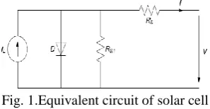
Fig. 1.Equivalent circuit of solar cell
The value of current depend on the incident solar irradiance, hence the characteristic equations involve the temperature co-efficient terms and also diode characteristics equation.
𝐼 = 𝐼𝐿𝑁𝑝− 𝐼𝑂𝑁𝑝 𝑒 𝑉+𝐼𝑅
𝑆𝑁 𝑠 𝑁 𝑝
𝑉𝑡𝑁𝑠𝑎 − 1 (1)
Where, k is the Boltzmann constant (1.38x10⁻²³) and a denotes the diode factor of 1.2.
To improve the performance of solar cell in wide range of temperature a modified Io current equation is formulated [5]
𝐼𝐿= 𝐼𝑝𝑣𝑛 + 𝑘𝐼 𝑇 − 𝑇𝑛 𝐺
𝐺𝑛 (2)
𝐼𝑜=
𝐼𝑠𝑐𝑛+𝑘𝐼∆𝑇
exp 𝑉𝑜𝑐𝑛 +𝑘𝑣∆𝑇
𝑎 𝑉𝑡 −1
(3)
Where 𝑇 − 𝑇𝑛 = ∆𝑇
The current temperature coefficient kIandvoltage temperature coefficient kV are included. G is denoted as the solar
Fig. 2:P-V characteristicscurve at Partial shading
Under partial shaded condition the P-V characteristics obtained generate more than one power point, making it difficult to operate in an optimum way as shown in figure 2. In this paper the analysis is made for a system with partial shaded condition. The section III gives a brief description about the proposed system. Section IV gives the results of the simulation.
III. INCREMENTAL RESISTANCE METHOD
The PV system is analyzed with a DC- DC boost converter for a resistive load.
Fig.3: The Basic block diagram of the system.
The system parameters are chosen by considering many factors as temperature and irradiance.
PV system:
A PV array KC200GT is taken for the analysis at STC with A. M 1.5. The modeling is done with equations 1, 2 and 3 with MATLAB/ SIMULINK
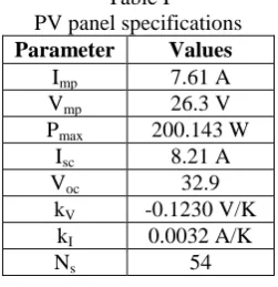
Table I PV panel specifications
Parameter Values
Imp 7.61 A
Vmp 26.3 V
Pmax 200.143 W
Isc 8.21 A
Voc 32.9
kV -0.1230 V/K
kI 0.0032 A/K
Ns 54
Boost converter:
𝑉𝑜
𝑉𝑖𝑛 =
1
1−𝐷 (4)
Where, D is the duty cycle of the converter. The Capacitor and inductor valuesare calculated accordingly with 30KHz as switching frequency.
𝐶 = 𝐷
𝑓×𝑅𝑜×(∆𝑉𝑜𝑉 )
(5)
𝐿 =𝑉𝑖𝑛×𝐷
𝑓×∆𝐼 (6)
Table 2
Converter Specifications
Parameter Values
C 500μF
L 5mH
Cfilter 470μF
Lfilter 3mH
Ro 300ῼ
Incremental Resistance MPPT algorithm:
For maximum power point tracking application, many algorithms have been developed in the recent years. The conventional and the simplest one is the hill climbing method. But as the field started to expand, the need for better algorithm increased. The Controllers are included with algorithms to get a better, efficient and stable maximum output. The basic focus in this paper is on incremental resistance algorithm. The algorithms so far implemented were efficient for conditions that are standardized. But for varying nature of climate more parameter variations are needed to be taken in to consideration. Incremental conductance method was introduced for the partial shaded analysis. But it was implemented only for fixed scaling factor[13].
For highly varying irradiance nature the scaling factor also needed to be changed.[14] The signals are changed in to discrete domain to achieve a varying scaling factor property.
𝑑𝑃𝑃𝑉
𝑑 𝑖𝑃𝑉 =
𝑑 𝑉𝑃𝑉×𝑖𝑃𝑉
𝑑 𝑖𝑃𝑉 =
𝑑𝑉𝑃𝑉
𝑑 𝑖𝑃𝑉 × 𝑖𝑃𝑉+ 𝑉𝑃𝑉 (7)
𝑒 =𝑑𝑃𝑃𝑉
𝑑𝑖𝑃𝑉 +
𝑉𝑃𝑉
𝑖𝑃𝑉 (8)
Since duty cycle is the required output from the controller to the converter, the error signal is multiplied with the scaling factor to obtain new duty cycle.
The maximum power point is tracked by checking on to these three conditions.
𝐷 𝑘 = 𝐷 𝑘 − 1 + 𝑁 × 𝑒 𝑘 ; 𝑒 𝑘 > 0 𝐷 𝑘 = 𝐷 𝑘 − 1 ; 𝑒 𝑘 = 0 𝐷 𝑘 = 𝐷 𝑘 − 1 − 𝑁 × 𝑒 𝑘 ; 𝑒 𝑘 < 0
It is clear that the scaling factor is an important parameter. With the change in scaling factor the power linearization is also varied. For simplicity fixed scaling factor of 0.38 is chosen in this paper.
IV. SIMULATION AND RESULTS
The System usesA PV array of KC200GTmodel with 3 module array considering a nominal residential load with help of MATLAB/SIMULINK. The system is simulated with the adaptive incremental resistance algorithm for partial shaded condition.
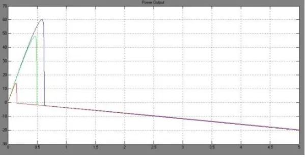
The major advantage of using INR along with boost converter is the ability to achieve a boosted power about 1kW. The algorithm is also able to tune well during any variation in the weather. From figure 5, the power output obtained without any controller at partial shading condition can be noted, with 1000w/m2, 800w/m2 and 500w/m2 irradiance
Fig. 5: Power Output for partial shading without controller.
Fig. 6: Power output due non uniform irradiance.
The duty cycle output obtained from INR controller is of very high frequency, as in figure 7four pulses are generated within every millisecond. Thus the switching of converter can be done much faster than any other controller.
Fig.7: Switching pulses from INR controller.
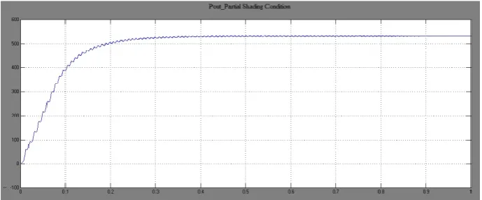
When implementing the incremental resistance method with nominal scaling factor for different irradiance at each module, a stabilized output is obtained. The scaling factor helps in maintaining a very high output power. The controller can be used to tune the power output between various peaks and ultimately finding the global maxima of the system.
From figure 8 it can be noted that the power output reaches a value of 0.5kW during the partially shaded condition of modules. Without the controller the power output will be the power output of the single module, with the INR MPPT controller the output is maintained the next highest possible value of the whole system capacity. Here the power variation is linear and with less transients.
V. CONCLUSION
Renewable energy resources are under microscopes in present scenario hoping to tap as much power as possible from every unit of its availability. Out of all sources, Photovoltaicsystem requires less stages of conversion making it much more reliable. Maximum power point tracking algorithms are used to improve system efficiency.From the developed algorithms proper choice of method is necessary to obtain the required outcome.
For partial shading condition a novel approach with incremental resistance algorithm is established. The analysis of the algorithm for various modes of shade is considered. In all modes INR method could generate a stabilized output with least transients. The power output can be boosted to very high value without disturbing the design aspect of the system.
REFERENCES
[1] MhamedRebhi, Ali Benatillah, MabroukSellam and BoufeldjaKadri, “Comparative Study of MPPT Controllers for PV System Implemented in the South-west of Algeria,” Energy Procedia 36 (2013) 142 – 153
[2]J. S. Christy Mano Raj and A. Ebenezer Jeyakumar, ,” A Novel Maximum Power Point Tracking Technique for Photovoltaic Module Based on Power Plane Analysis of I–V Characteristics” IEEE Transactions On Industrial Electronics, Vol. 61, No. 9, September 2014
[3]KashifIshaque, Zainal Salam, Muhammad Amjad, and SaadMekhilef, “An Improved Particle Swarm Optimization (PSO)–Based MPPT for PV with Reduced Steady-State Oscillation,” IEEE Transactions on Power Electronics, Vol. 27, No. 8, August 2012
[4] H. Bounechbaa, A. Bouzida, K. Nabtib and H. Benallab, “Comparison of perturb & observe and fuzzy logic in maximumpower point tracker for PV systems”,The International Conference on Technologies and Materials for Renewable Energy, Environmentand Sustainability, TMREES14, pp. no:677 – 684
[5] Ganesh Pachpande, Prof. Pankaj H. Zope, “Studying the effect of shading on Solar Panel using MATLAB,” International Journal of Science and
Applied Information Technology, ISSN No. 2278 -3083 Volume 1, No.2, May – June 2012
[6]Ali Bidram, Ali Davoudi, and Robert S. Balog, “Control and Circuit Techniques to Mitigate Partial Shading Effects in Photovoltaic Arrays,” IEEE Journal of Photovoltaics, Vol. 2, No. 4, October 2012
[7]ekeshwar Prasad Sahu, T.V. Dixit and Ramesh Kumar, “Simulation and Analysis of Perturb and Observe MPPT Algorithm for PV Array Using ĊUK converter”, Research India, ISSN 2231-1297, Volume 4, Number 2 (2014), pp. 213-224
[8] F. Liu, S. Duan, F. Liu, B. Liu, and Y. Kang, “A variable step size INCMPPT method for PV Systems,” IEEE Trans. Ind. Electron., Vol. 55,No.7, pp. 2622-2628, Jul. 2008
[9]Qiang Mei, Mingwei Shan, Liying Liu, and Josep M. Guerrero, “A Novel Improved Variable Step-Size Incremental-Resistance MPPT Method for PV Systems”, IEEE Transactions On Industrial Electronics, Vol. 58, No. 6, June 2011
[10]RaghavKhanna, Qinhao Zhang, William E. Stanchina, Gregory F. Reed, and Zhi-Hong Mao, “Maximum Power Point Tracking Using Model Reference Adaptive Control,” IEEE Transactions On Power Electronics, Vol. 29, No. 3, March 2014
[11]Chih-Yu Yang, Chun-Yu Hsieh, Fu-KueiFeng, and Ke-Horng Chen, “Highly Efficient Analog Maximum Power Point Tracking (AMPPT) in a Photovoltaic System,” IEEE Transactions on Circuits and Systems—I: Regular Papers, Vol. 59, No. 7, July 2012
[12]AbdKadirMahammad, SharifahSaon and Wong SweeChee, “Development of Optimum Controller based on MPPT for Photovoltaic System during Shading Condition,” Procedia Engineering 53 (2013) 337 – 346