www.ijiset.com
The Effects of Inlet Temperature on Heat Transfer Behaviours
of Evaporation in Rectangular Microchannels
Batan Le, Vanmanh Nguyen, and Thanhtrung Dang
Department of Thermal Engineering, Ho Chi Minh City University of Technology and Education, Vietnam
Abstract
In this paper, the effects of inlet water temperature on heat transfer behaviours of evaporation in rectangular microchannels were investigated by numerical simulation and experiments. The inlet temperature was varied from 400C to 600C for finding out the best performances. In this study, the inlet temperature of 400C is the best choice for designing of microchannel heat sinks and the total heat flux is about 57.74 W/cm2. Besides, the steam output temperature increases with increasing of inlet water temperature in both numerical simulation and experimental data. The exit vapour quality also increases with increasing of inlet temperature in numerical simulation; however, the values of increments in all of cases are very small. In addition, the effect of mass flow rate to the time of occurring nucleation site and full evaporation was also investigated. The results obtained from numerical simulation were in good agreement with experimental data, with percentage errors were less than 2 %.
Keywords: Microchannel, Evaporation, Temperature, Velocity, Numerical simulation.
1. Introduction
One of the most interesting topics in this decade is energy saving and environmental protection. In the conventional heat exchangers, they have very big size and low heat transfer efficiency. Hence, it necessarily becomes to replace the traditional big size heat exchangers by the small size microchannel heat exchangers which giving higher heat transfer efficiency. Therefore, it is very necessary to make a deeply research about microchannel heat exchangers. Related to heat transfer behaviors in microchannel heat sinks, Kuppusamy et al. [1] studied the alternating slanted passage in the channel wall as a secondary flow. The results showed that when comparing the alternating slanted passage microchannel heat sink with the conventional one, the overall performance of microchannel heat sink with alternating slanted passage increased by 146% and thermal resistance reduced to 76.8%.
Singh et al. [2] studied the rectangular microchannels which were fabricated with varying aspect ratios (width to depth) but the hydraulic diameter was not changed and had a value of 142 ± 2 µm and length of 20 mm. In this study, the working fluid was water. They focused on the impact of the aspect ratio on the overall pressure drop involving water boiling in the microchannels for two phase flow. In this paper, the experimental results showed that the pressure drop has a minimum value at an aspect ratio of 1.6. Balasubramanian et al. [3]conducted the flow boiling experiments in straight and expanding microchannels with similar operating conditions in order to choose the best performances of microchanel heat sink. The working fluid is deionized water and the material is copper. The microchannels have the width of 300µm, the depth of 1153 µm, the substrate of 25 mm x 25 mm, the aspect ratio of 4. In this paper, the results showed that the expanding microchannel heat sink has a better heat transfer performance than the straight one. Besides, the two phase pressure drop across the expanding microchannel heat sink is significantly lower 30% than straight one.
microchannels have superior heat transfer performance than straight microchannels when they compared the heat transfer performance of the wavy microchannels with straight microchannels. Law et al. [6] carried out experiments in straight- finned and oblique- finned microchannels for flow boiling with similar operating conditions in order to compare heat transfer and pressure characteristics. The channel is in the shape of rectangular, of up to 1.7 times at the highest comparable heat flux.
Megahed et al. [7] investigated in heat transfer and pressure drop characteristics of a cross-linked microchannel heat sink for two phase flow at low mass fluxes and high heat fluxes. There are 45 straight rectangular microchannels with dimension of W=300 µm, H=120 µm, working fluid of FC. The results showed the heat transfer performance of the oblique-finned microchannels is significantly better than its straight-finned counterpart, with augmentations in heat transfer coefficient of between 1.2 and 6.2 times. Two-phase pressure drop in the oblique-finned microchannels is consistently higher than the straight-finned microchannels, with a rise the hydraulic diameter of 248µm, the working fluid of FC-72. They also introduced three cross-links with the width of 500µm perpendicular to the microchannels. The experiments were carried out a range of heat flux from 7.2 to 104.2 kW/m2, with mass flux from 99 to 290 kg/m2s and exit quality from 0.01 to 0.71. The results showed that the two-phase pressure drop in cross-linked microchannel heat sink strongly increases with the exit quality less than 0.3, and also increases 1.6 – 2 times comparing to the straight one. Besides, at a constant mass flux, the flow boiling heat transfer coefficient increases with increasing exit quality.
Ling et al. [8] investigated in the flow characteristics of round quartz microchannels under pressure driving force. The microchannels have the diameters of 13 µm, 20 µm and the range of lengths from 40mm to 100mm. Besides, the relationship between the flow rates and pressure drop was well investigated. The results showed that the relationship between the flow rates and pressure is linearity; however, there are differences between experiments and theory for the diameter of 20 µm, and the experimental flow rate is less than predicted. Moreover, the flow characteristics of the microchannels are basically
Yun et al. [9] concluded that the boiling heat transfer coefficients in their designed rectangular microchannels are much higher than those in large or small diameter single tubes at similar test conditions. Besides, they also showed that the pressure drop increased with increasing mass flux at constant saturation temperature. Pressure drop decreased with increasing saturation temperature at given mass flux. They investigated in the convective boiling heat transfer coefficients and two-phase pressure drops of rectangular microchannels. The microchannels have the hydraulic diameters of 1.36 and 1.44 mm. R410A was used as a working fluid. The mass flux was varied from 200 to 400 kg/m2s, heat flux from 10 to 20 kW/m2.
Schilder et al. [10] carried out the experiments in a circular tube with a diameter of 600 µm and working fluid of ethanol. They compared the pressure drop and the convective heat transfer characteristics for both two phase flow and single phase flow. The results showed that, the Nusselt number for two phase flow is not depend on the heat flux, increases with increasing mass flux density, up to eight times higher than that for single phase flow. Besides, the mean pressure drop for two phase flow is about three times higher than that for single phase flow. Pressure drop of heat sink was studied on silicon microchannels by Megahed et al. [11]. In this paper, the microchannels were in the shape of rectangular with a depth of 276µm, a width of 225µm, and a length of 16mm. Experiments were carried out with the FC-72 working fluid and these following conditions: the ranges of mass fluxes from 341 to 531 kg/m2s and heat fluxes from 60.4 to 130.6 kW/m2. They concluded that the two phase pressure drop depends strongly on the mass flux, and increases almost linearly with increasing exit quality at a constant mass flux.
www.ijiset.com
pressure drop increased linearly with Reynolds number. Lee et al. [13] focused on high heat flux microchannel heat sink in refrigeration cooling applications for two-phase flow. A rectangular microchannel evaporator which has the dimension of 231µm wide x 713µm deep was considered in a refrigeration cycle. The experiments were carried out with the working fluid of R134a and these following conditions: inlet pressure of Pin = 1.44 – 6.60 bar, mass
velocity of G = 127–654kg/m2s, inlet quality of xe,in =
0.001–0.25, outlet quality of xe,out = 0.49–superheat, and
heat flux of q’’ = 31.93.8W/cm2. The results showed that
the total pressure drop generally increases with increasing mass velocity and/or heat flux.
Barlak et al. [14] carried out the experiments in the pressure drop and friction factor in microtubes. The range of diameters form is from 0.20 mm to 0.589 mm, a range of Reynolds number from 100 to 10000 and the ratios of length to diameter form 16 to 265, working fluid of distilled water. The results showed that, the L/d ratio has an important effect on the apparent friction factor in case of L/d < 100. Besides, the transition of critical Reynolds number is between 2000 and 2500. Lee et al. [15] developed rectangular microchannel heat sinks with difference dimensions: the width from 102 µm to 997 µm, the depth of 400 µm for all of cases, footprint of 1.27 cm x 1.27 cm. Deionized water was used as a working fluid. The results showed that the pressure drop increases rapidly with heat flux when the incipience heat flux is exceeded. Besides, they also showed that: at low to medium heat fluxes, the local heat coefficient increases almost linearly with heat flux. At higher heat fluxes, the saturated heat transfer coefficient does not change when increasing heat flux for the range tested.
As reviewed above, there is no more research focus on the inlet temperature which strongly effect to heat transfer behaviors. Therefore, it is important to clearly understand the effects of inlet temperature on heat transfer behaviors for design. For the present study, a microchannel heat sink with rectangular cross sections will be studied to achieve its evaporation phenomena.
2. Methodology
2.1 Structure design
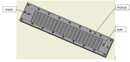
The rectangular microchannel heat sink using in this study is illustrated in Figure 1. It consists of microchannels and manifold which were milled in the substrate; the PMMA cover and 20 bolts were used to fasten the substrate and cover strongly. All microchannels were connected to the manifolds for both sides. At first, water from the manifold inlet flows through microchannels, then going out of the system by outlet manifold. During its journey, it receives amount of heat - which supplied by the outside sources - to become vapor at the manifold outlet.
Figure 1. Rectangular microchannel heat sink
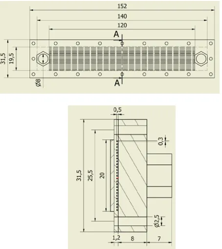
The microchannel heat sink has 20 microchannels. The length of each microchannel is 120 mm, the depth is 0.5mm, and the width is 0.3 mm. The distance between two microchannels is 500 µm. The thickness of the substrate is 1.2 mm. In a microchannels heat sink, all channels are connected to a manifold for both sides. The manifolds of the heat sink have a rectangular cross-section with a width of 10 mm, a length of 19.5 mm and a depth of 0.5 mm. The Figure 2 shows the dimensions of the rectangular microchannels heat sink.
Figure 2. The dimensions of the microchannel heat sink
2.2 Numerical Simulation
In this study, the conjugate 3D flow and heat transfer models of the COMSOL software package were employed to analyze the flow and heat transfer characteristics of the microchanel heat sink.
The computational model was employed, including all of the parts of the microchannel heat sinks: Substrate, microchannels, inlet, outlet paths, as presented in Fig. 1; and its dimensions are shown in Fig. 2.
For the numerical simulation, there are some following assumptions:
(1) Flow is assumed to be three-dimensional, two phase flow, time dependent, incompressible and laminar. (2) Thermophysical properties of fluid and solid are assumed to be temperature independent.
(3) Gravitational force is neglected, and there is no internal heat generation within the model.
(4) The walls of the channel have a no-slip condition for velocity and temperature
The governing equations describing the microchannel heat sink consists of the continuity equation (1), momentum equations (2a, 2b, 2c), energy equation (3) and equations of k-ε model (4-9) in 3D Cartesian coordinates can be shown by:
(1) (2a) (2b) (2c) (3) (4) (5) ε ρ µ µ 2 k C T = (6) u k u u u u
Pk T T .
3 2 ) . ( 3 2 ) ) ( (
: 2− ∇
∇ ∇ + ∇ − ∇ =µ ρ (7) Q T k T u C t T
Cp ∂ + p ∇ =∇ ∇ +
∂ ) .( . ρ ρ (8)
(
)
(
)
T L C C C m phase phase phase phase p δ δα θ θ ρ ρ ρ + − ρ ρ += 1 1 1 2 2
1 (9)
where T is temperature, t is time, c is specific heat at constant pressure, ρ is density, µ is dynamic viscosity, k is thermal conductivity and turbulent kinetic energy, Qi is
internal heat generation, u is velocity, p is pressure, ε is rate of viscous dissipation.
For time dependent solver:
∂ u/∂ t ≠ 0 (10) ∂ T/∂ t ≠ 0 (11)
The boundary conditions of inlet flow are:
u = u0 (12)
T = T0 (13)
For the energy transport, the walls have no-slip conditions for velocity and temperature at the walls; these conditions are expressed by:
uwall= 0 (14)
Twall = Twater at wall (15)
And the internal heat generation is:
Qi = 0 (16)
Figure 3 shows the schematic nodalization of the heat exchanger with 48,968 mesh elements and a relative tolerance of 10-6.
0
u v w
u v w
t x y z x y z
ρ ρ ρ ρ ρ
∂ + ∂ + ∂ + ∂ + ∂ +∂ +∂ =
∂ ∂ ∂ ∂ ∂ ∂ ∂
2 2 2
2 2 2
1
u u u u p u u u
u v w
t x y z x x y z
µ ρ ρ ∂ + ∂ + ∂ + ∂ = − ∂ + ∂ +∂ +∂ ∂ ∂ ∂ ∂ ∂ ∂ ∂ ∂
2 2 2
2 2 2
1
v v v v p v v v
u v w
t x y z x x y z
µ ρ ρ ∂ + ∂ + ∂ + ∂ = − ∂ + ∂ +∂ +∂ ∂ ∂ ∂ ∂ ∂ ∂ ∂ ∂
2 2 2
2 2 2
1
w w w w p w w w
u v w
t x y z x x y z
µ ρ ρ ∂ + ∂ + ∂ + ∂ = − ∂ + ∂ +∂ +∂ ∂ ∂ ∂ ∂ ∂ ∂ ∂ ∂
2 2 2
2 2 2 i
p
T T T T T T T
u v w Q
t x y z C x y z
λ ρ ∂ + ∂ + ∂ + ∂ = − ∂ +∂ +∂ + ∂ ∂ ∂ ∂ ∂ ∂ ∂ ρε σ µ µ ρ ρ + − ∇ + ∇ = ∇ + ∂ ∂ k k T P k k u t k ). ( . ). . ( ep k C P k C u
t e k e
T + − =
www.ijiset.com
Figure 3. Grid mesh diagram of the microchannel heat sink
2.3 Experimental Setup
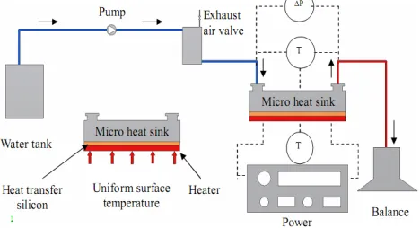
Figure 4 shows the schematic diagram of test loop. In this study, pure water is the working fluid. Accuracies of apparatuses are listed in Table 1.
Figure 4. The schematic diagram of test loop
The MEMs technology was used for fabricating microchannel heat sinks. Some devices were used for experimental setup:
1. Temperature sensors: T - types
2. Pumps PU-2087, manufactured by Jasco 3. Resistance, AXW-8, manufactured by Medilab 4. Pressure sensor, PMP4110, manufactured by Duck 5. Electric balance, TE-214S, manufactured
by Sartorious.
Table 1. An accuracy of instruments
Parameters Tolerance
Temperature ± 0.1 °C
Pressure ± 0.025% FS
Mass flow rate ± 0.0015 g Channel Depth ± 7 µm Channel width ± 10 µm Channel Length ± 70 µm
3. Results and Discussion
As described above, one of the most important factors affecting heat transfer behaviors is inlet temperature. So, finding the best value of inlet temperature is the important task to determine the optimal design of two phase flow microchannel heat sinks. In order to study its effects, all numerical simulation and experiments conditions were kept the same excepting the inlet temperature was varied from 400C to 600C. Table 2 shows the general parameters for simulation and experiments.
Table 2. General parameters
Variable parameters Fixed parameters
Inlet temperature:
t1 = 400C
t2 = 450C
t3 = 500C
t4 = 55 0
C
t5 = 600C
Heat power:
Psource = 132 W
Mass flow rate:
min = 0.3 g/s
Ambient temperature:
Tamb = 30 °C
Source temperature:
TS = 120 °C
Cross-section area:
A = 0.15 mm2
Figures from 5 to 9 show the location of full vaporization of the water in rectangular microchannels in case t1, t2, t3, t4, t5 by simulations. It was observed that the
flow rate in middle channels is larger than in marginal channels, so the full vaporization of middle channels is slower than that obtained from the marginal channels, leading to the vaporization profile is parabolic shape. The process of experiments were carried out with input parameters the same as parameters of the simulation as Table 2.
Table 3. Results between experiment and simulation
Inlet temperature
0
C
Oulet temperature, 0C X
e
Simulation
Simulation Experiment
40 99.4 99.6 0.99024
45 99.45 99.6 0.99293
50 99.48 99.7 0.99344
55 99.51 99.7 0.99451
The Table 3 showed the results of outlet temperature and vapor quality between experiment and simulation. The results show that the steam output temperature increases with increasing of inlet water temperature in both numerical simulation and experimental data. The exit vapor quality also increases with increasing of inlet temperature in numerical simulation; however, the values of increments in all of cases are very small. The maximum exit qualities gained at the end of channels in case t5 =
600C is xe = 0.99501 as showed in Figure 10.
Figure 5. The location of full evaporation of the water in case t1 = 400C
Figure 6. The location of full evaporation of the water in case t2 = 450C
Figure 7. The location of full evaporation of the water in case t3 = 500C
Figure 8. The location of full evaporation of the water in case t4 = 550C
Figure 9. The location of full evaporation of the water in case t5 = 600C
Figure 10. The vapour quality in case t5 = 600C
Figure 11. The boiling position vs. inlet temperature
Figure 11 shows the effects of inlet temperature to the boiling position in the microchannel. It shows that the inlet temperature increase with the decrease of boiling position in the channel. For the inlet temperature of 400C, the boiling position is about at 55 cm and 52 cm site (the total length of microchannels is 120 cm) in simulations and experiments, respectively.
Figure 12 shows the fluctuation of heat flux during the change of inlet temperature from 400C to 600C by numerical simulation and experimental data.
www.ijiset.com
In order to determine the best value of inlet temperature for two-phase flow, the heat transfer phenomena – such as the total heat fluxes (x-direction), the phase transition, and the exit qualities of the sample - were carried out by using the COMSOL Multiphysics - version 5.2a as mentioned above. Thus, as seen in Figure 12, the inlet temperature is selected to be 400C which giving the highest heat flux due to its high exit quality. The maximum heat flux is about 57.72 W/ cm2.
Moreover, for reducing the time of occurring nucleation site, some numerical simulations and experimental data were carried out by increasing the mass flow rate from 0.3g/s to 0.6g/s. Figure 13 shows the effects of mass flow rate to the nucleation site. It was observed that the time of occurring nucleation site increases with raising the inlet mass flow rate.
Figure 13. Inlet water temperature vs. the time occurring nucleation site
It was noted that the numerical simulations from Figs. 5-10 are the new results for entire system (consisting of the inlet/outlet holes, manifolds, and channels) and two-phase flow. They have not seen in literature reviews.
4. Conclusions
For finding out the effects of inlet temperature on heat transfer behaviours of evaporation in rectangular microchannel heat sinks, the numerical simulation and experimental data have been done with the varying of inlet temperature from 400C to 600C. It was indicated that the steam output temperature increases with rising the inlet water temperature in both numerical simulation and experimental data. The exit vapour quality also increases with increasing of inlet temperature in numerical simulation; however, the values of increments in all of cases are very small. The rectangular microchannel heat sink with the inlet temperature of 400C is the best choice for designing (Based on the fixed parameters as mentioned
above) and the total heat flux is about 57.72 W/cm2. In addition, the time of occurring the nucleation site and full evaporation decreases with reducing of mass flow rate. There was less than 2% error between numerical simulation and experimental data. The numerical simulations in this study are carried out for all of the parts of the system (consisting of the inlet/outlet holes, manifolds, and channels) in two-phase flow considering. These results are the new approaches for the numerical simulation.
Acknowledgments
The supports of this work by the project (Project No. T2016–85TĐ sponsored by Ho Chi Minh City University of Technology and Education, Vietnam) are deeply appreciated.
References
[1] Navin Raja Kuppusamy, R. Saidur, N.N.N. Ghazali, H.A. Mohammed, Numerical study of thermal enhancement in micro channel heat sink with secondary flow, International Journal of Heat and Mass Transfer 78 (2014) 216-223.
[2] S.G. Singh, A. Kulkarni, S.P. Duttagupta, B.P. Puranik, A. Agrawal, Impact of aspect ratio on flow boiling of water in rectangular microchannels, Experimental Thermal and Fluid Science 33 (2008) 153–160.
[3] K. Balasubramanian, P.S. Lee,L.W.Jin, S.K. Chou, C.J. Teo, S. Gao, Experimental investigations of flow boiling heat transfer and pressure drop in straight and expanding microchannels - A comparative study, International Journal of Thermal Sciences 50 (2011) 2413 – 2421.
[4] Guodong Wang, Ping Cheng, A.E. Bergles, Effects of inlet/outlet configurations on flow boiling instability in parallel microchannels, International Journal of Heat and Mass Transfer, 51 (2008), pp. 2267-2281
International Journal of Heat and Mass Transfer 85 (2015) 797– 810.
[7] A. Megahed, Experimental investigation flow boiling characteristics in a cross-linked microchannel heat sink, International Journal of Multiphase Flow 37 (2011) 380–393. [8] Z.Y.Ling, J.N.Ding, J.C.Yang, Y.Liu, Z.Fan, P.Yang and Z.W.Zhuang, Experimental Study of Flow Characteristics of Distilled Water under Pressure Driven in Microchannel, Proceedings of the 1st IEEE International Conference on Nano/Micro Engineered and Molecular Systems January 18 - 21, 2006, Zhuhai, China.
[9] Rin Yun, Jae Hyeok Heo, Yongchan Kim, Evaporative heat transfer and pressure drop of R410A in microchannels, International Journal of Refrigeration 29 (2006) 92–100. [10] Boris Schilder, Simon Yu Ching Man, Nobuhide Kasagi, Steffen Hardt, Peter Stephan, Flow Visualization and Local Measurement of Forced Convection Heat Transfer in a Microtube, Journal of Heat Transfer, 2010, Vol. 132.
[11] A. Megahed, I. Hassan, Two-phase pressure drop and flow visualization of FC-72 in a silicon microchannel heat sink, International Journal of Heat and Fluid Flow 30 (2009) 1171– 1182.
[12] O. Barlay Ergu, O.N. Sara, S. Yapıcı, M.E. Arzutug, Pressure drop and point mass transfer in a rectangular microchannel, International Communications in Heat and Mass Transfer 36 (2009) 618–623.
[13] Jaeseon Lee, Issam Mudawar, Two-phase flow in high-heat-flux micro-channel heat sink for refrigeration cooling applications: Part I––pressure drop characteristics, International Journal of Heat and Mass Transfer 48 (2005) 928–940.