Design and Implementation of Tilted Flap
Type Vertical Axis Wind Turbine
R. V. Borkar1, Vivek Mahore2, Akshay Rajput3, Aniket Sonawane4, Alfiya Mokashi5 Assistant Professor, P.E.S’s. Modern College of Engineering, Pune, India1
BE, Department of Electrical, P.E.S’s. Modern College of Engineering, Pune, India2
BE, Department of Electrical, P.E.S’s. Modern College of Engineering, Pune, India 3
BE, Department of Electrical, P.E.S’s. Modern College of Engineering, Pune, India 4
BE, Department of Electrical, P.E.S’s. Modern College of Engineering, Pune, India 5
ABSTRACT: Development of renewable energy sources is accelerating due to soaring oil prices and the depletion of fossil fuels, Water supplies such as wells and dugouts can often be developed on the open range. However, the availability of power supplies on the open range is often limited, so some alternate form of energy is required to convey water from the source to a point of consumption. Wind energy is an abundant source of renewable energy that can be exploited for pumping water in remote locations, and windmills are one of the oldest methods of harnessing the energy of the wind to pump water. The agriculture in our country is highly dependent on rainfall. The system is fully based on renewable energy which is always available without any limitations. Technological improvement in system and a new designed wind turbine makes system more efficient. So this scheme can be implemented for irrigation purpose to solve the problem of load shedding. In this way wind power helps to farmer to reduce cost of electricity and have good advantage if additional power supplied to utility grid.
To supply remote houses using Stand-alone wind energy systems with storage battery banks are commonly used. The model of wind turbine is developed using basic wind power equation for vertical axis wind turbine. Generator, with a feature of variable-speed operation, has been used. Since the speed of wind turbine is variable and much lower a gearbox is used to increase the rotor speed of generator, the power output of generator also increases. A rectifier is used to rectify the output voltage of generator. A standalone model of tilted flap type wind turbine supplying electric energy to load is modeled and analyzed for different wind speed.
KEYWORDS:Tilted Flap Type Wind Turbine, , Rectifier, Boost Converter, DC Generator
I. INTRODUCTION
Energy is required for wide range of applications such as transportation, industrial applications, agriculture applications, household and office requirements etc. There are various forms of energy such as heat energy, chemical energy, electrical energy, nuclear energy etc. among them electrical energy is widely used. Hence its supply should be secure and sustainable, economical, environment friendly and socially acceptable. The current trend in energy consumption is neither secure not sustainable. The rise in consumption of fossil fuels (and associated prices), together with increasing greenhouse gas emission, threatens our secure energy supply. Therefore the development of clean, secure, sustainable and affordable energy source such as renewable energy should be possible although with reduced power output.
Now a day’s renewable source of energy is widely used for the generation of electrical energy. The renewable sources generates very low voltage hence the step up DC-DC converters are widely used for various applications. The wind energy conversion system is considered to play important role in future energy production for various applications.
II. SYSTEM MODEL AND ASSUMPTIONS 2.1 Wind Turbine
The blades of a wind turbine extract the energy flow from moving air, which then converts this energy to rotational energy and delivers it via a mechanical drive unit to the rotor of an electric generator. The kinetic energy in air of an object of mass moving with speed v is equal to:
=1
2 ( )… … … (1)
The power in the moving air, if we assume constant wind velocity, is:
= =1
2 … … … . … (2)
Where is mass flow rate per second. When the air passes across an area A, such as the area swept by the rotor
blades, the power in the air can be estimated:
=1
2 ( ) … … … (3)
Where ρ is the air density, the air density varies with air pressure and temperature, therefore ρ=1.225 kg/m3 for the
purpose of this thesis.
Due to the aerodynamic losses that depend on the rotor design and construction (number of blades, weight, stiffness
etc.), the maximum power can be extracted from the wind is expressed as follows.
= 0.5 … … … . (4)
Where is the power coefficient of the rotor or the rotor efficiency, in this paper following power coefficient
analytical function is used to model the turbine:
(λ,β) = 1
Λ− − − … … … (5)
Where λ is the tip speed ratio (TSR), it is the ratio between tip speed of the blade and wind speed (v). Is the blade
pitch angle it will increase when high wind speed is occurred to turn out the blade from facing the wind hence there
will be damage in wind generator can be avoided. The coefficient of c1-c6 and x can be different for various turbines.
They depend upon the wind turbine rotor and blade design. The parameter 1/Λ is defined as:
1
Λ=
1
Λ+ 0.08β
0.035
1 + … … … . … (6)
The coefficients C1 to C6 are: C1=0.5176, C2 =116, C3 =0.4, C4 =5, C5 =21, C6 =0.0068. For the value of pitch
angle zero and TSR is 8.1 the maximum power coefficient 0.48 can be achieved. As scientist Betz derived the betz limit is that theoretical value 59.3% of wind power can be extracted, but in case practical design maximum achievable is between 0.4 and 0.5 for high speed two blade turbines and 0.2 to 0.4 for low speed turbines with more blades. Assuming the wind speed and blade pitch angle are constant, then power coefficient ( ) becomes the function of rotor speed (ωr) hence for each wind speed there is one rotor speed that will yield maximum power, making the system
monotonic. The mechanical torque of the wind turbine can be calculated as follows.
= … … … (7)
Wind turbines can be classified in a first approximation according to its rotor axis orientation and the type of aerodynamic forces used to take energy from wind.
2.2 TYPES OF WIND TURBINE
Horizontal-Axis Wind Turbines (HAWT) has the fundamental rotor shaft and electrical generator at the highest point of a pinnacle and should be pointed into the breeze. Little turbines are pointed by a basic breeze vane, while substantial turbines by and large utilize a breeze sensor combined with a servo motors. Most have a gearbox, which transforms the moderate turn of the sharp edges into a faster revolution that is more appropriate to drive an electrical generator.
Figure.1: Horizontal Axis Wind Turbine
Vertical Axis Wind Turbines (VAWTs) are a sort of turbine where the principle rotor shaft runs vertically. These turbines can turn unidirectional even with bidirectional liquid stream. VAWT is predominantly because of the benefits of this sort of machine over the even pivot compose, for example, their straightforward development, the absence of need of over speed control, the acknowledgment of twist from any course of the mechanical plan restrictions because of the control frameworks and the electric generators are set up statically on the ground.
Figure.2: Vertical Axis Wind Turbine
What is the Flap Turbine?
The Flap Turbine (FT) is a novel type of vertical axis turbine (VAWT) where the blades are made of movable flaps. These movable flaps, act as a blade for the VAWT. This type of turbine is also known as a check valve turbine because of the check valve like the behavior of the moving flaps. When the sail is moving in the downwind direction, the flaps are opened and will not allow air to pass through the sail.
However, when the sail is moving in the upwind direction the flaps will be in the open position and allow air pass through the sail
Drag Force
Lift Force
The lift type uses an aerodynamic airfoil to create a lift force, they can move quicker than the wind flow. This kind of windmills is used for the generation of electricity. The most representative model of a lift-type VAWT is the Darrieus turbine; its blades have a troposkien shape which is appropriate for standing high centrifugal forces
Advantages
• Low speed vertical axis wind turbine • Return Drag Causes Rotor to slow down • Efficiency gets increased
• Constant Drag cause by the blades moving against wind on the upstream side of the rotor
2.3. Proposed System 2.3.1 Design Model
Figure.3: Design Model
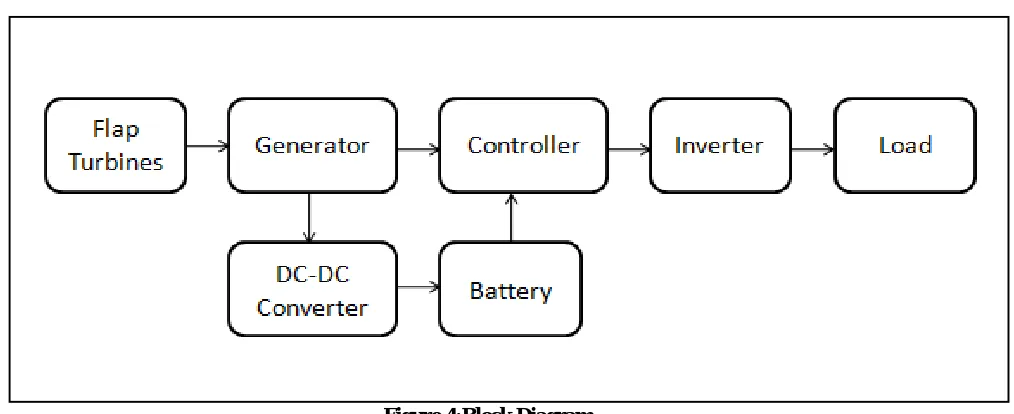
2.3.2 Block Diagram of Tilted Flap Type Vertical Axis Wind Turbine
Figure 4:Block Diagram 1. Flap
Turbine:-The most important characteristics of the FT, which is self-starting and omnidirectional, is that the flaps are operated by the wind and not with complex mechanisms.
2. Generator (DC 12V 500 RPM) :-
A machine that converts mechanical energy into electricity to serve as a power source for other machines. Electrical generators found in power plants use water turbines, combustion engines, windmills, or other sources of mechanical energy to spin wire coils in strong magnetic fields, inducing an electric potential in the coils. A generator that provides alternating current power is called an alternator
3. Battery (12V 1.3Ah)
The batteries in the system provide to store the electricity that is generated from the wind or the solar power. Any required capacity can be obtained by serial or parallel connections of the batteries. The battery that provides the most advantageous operation in the solar and wind power systems are maintenance free dry type and utilizes the special electrolytes. These batteries provide a perfect performance for long discharges.
4. Inverter(IC 1805)
Energy stored in the battery is drawn by electrical loads through the inverter, which converts DC power into AC power. The inverter has in-built protection for Short-Circuit; Reverse Polarity, Low Battery Voltage and Over Load.
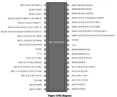
5. Controller (PIC18F4550):
Figure 5:Pin Diagram
6. DC to DC Converter (Boost Converter):
The boost converter performs a function of converting the unregulated voltage which causes fluctuation in the line to regulated dc output with increase voltage level. It is used in switch mode power supply and in dc motor application. The relation between the input and output voltage and current of the boost converter is expressed by the following equations.
Vin=1/(1-D)*Vout ...[1]
Iin=(1-D)*Iout ...[2]
III. RESULT
Table 1: Result Table
Sr. No. Wind Speed(M/sec) Output Voltage(V)
1 7 3.3
2 10 3.5
3 15 4.1
4 20 4.6
From the above result table we came to know that output voltage is directly proportional to wind speed.
IV. CONCLUSION
This paper presents wind turbine with mounting flap onto vertical axial wind turbine, the project found that flap can efficiently control aerodynamic performance of airfoil. mounting flap can raise the maximum lift of airfoil, decrease airfoil drag under suitable flap height, raise airfoil lift-to-drag ratio, and thus to enhance the aerodynamic performance of wind turbine.
REFERENCES
[1] R.V.Borkar “Modeling and Simulation of Wind Powered Permanent Magnet Direct Current (PMDC) Motor“ International Journal of Science
and Research (IJSR) ISSN (Online): 2319-7064 Index Copernicus Value (2013): 6.14 | Impact Factor (2013)
[2] Liebeck R H. Design of Subsonic Airfoils for High Lift, Journal of Aircraft, Vol. 15, No. 9, 1978, pp. 547-561