555-233-200
Comcode 108678673
Issue 1
April 2000
Release 8.2
Printed in U.S.A.
Notice
Every effort was made to ensure that the information in this book was complete and accurate at the time of printing. However, information is subject to change. This document was prepared by the Lucent Technologies Product Publications, Denver, CO Your Responsibility for Your System’s Security
Toll fraud is the unauthorized use of your
telecommunications system by an unauthorized party, for example, persons other than your company’s employees, agents, subcontractors, or persons working on your company’s behalf. Note that there may be a risk of toll fraud associated with your
telecommunications system and, if toll fraud occurs, it can result in substantial additional charges for your telecommunications services. You and your system manager are responsible for the security of your system, such as programming and configuring your equipment to prevent unauthorized use. The system manager is also responsible for reading all installation, instruction, and system administration documents provided with this product in order to fully understand the features that can introduce risk of toll fraud and the steps that can be taken to reduce that risk. Lucent Technologies does not warrant that this product is immune from or will prevent unauthorized use of common-carrier telecommunication services or facilities accessed through or connected to it. Lucent
Technologies will not be responsible for any charges that result from such unauthorized use.
If you suspect that you are being victimized by toll fraud and require assistance, contact the Toll Fraud Intervention Hotline at +1 800 643 2353 or contact your local Lucent representative.
How to get help
If you need additional help, the following services are available. You may need to purchase an extended service agreement to use some of these services. Contact your Lucent representative for more information.
DEFINITY Helpline +1 800 225 7585 (for help with feature administration and system applications)
Lucent Technologies National Customer Care Center Support Line +1 800 242 2121 (for help with maintenance and repair)
Lucent Technologies Toll Fraud Intervention +1 800 643 2353
Lucent Technologies Corporate Security +1 800 822 9009
--Western Europe/Middle East +44 1252 77 4800 /South Africa
--Central/Eastern Europe +361 645 4334 --Central/Latin America/Caribbean +1 303 804 3778 --Australia 61-2-9352-9090 --North America +1 800 248 1111 Standards Compliance
The equipment described in this book complies with the following standards, as applicable:
Electromagnetic Compatibility Standards
This product complies with and conforms to the following, as applicable:
Federal Communications Commission Statement
Part 68: Answer-Supervision Signaling. Allowing this
equipment to be operated in a manner that does not provide proper answer-supervision signaling is in violation of Part 68 rules. This equipment returns answer-supervision signals to the public switched network when
• answered by the called station, • answered by the attendant, or
• routed to a recorded announcement that can be administered by the CPE user.
Australia AS3548 (AS/NZ3548)
FCC Part 15 and Part 68
ITU-T (Formerly CCITT)
CSA C222 Number 225
ANSI EN55022 IEC 950 ISO-9000 CISPR22 EN50081 IPNS TS001 DEFINITY® EN50082 National
ISDN-1
National ISDN-2 DPNSS ETSI UL 1459 UL 1950I ECMA IEC 825
Limits and Methods of Measurements of Radio Interference Characteristics of Information Technology Equipment, EN55022 (CISPR22), 1993
EN50082-1, European Generic Immunity Standard FCC Part 15
Australia AS3548
The DEFINITY ECS conforms to Class A (industrial) equipment. Voice terminals conform to Class A equipment per the following standards.
• A reorder tone is received.
Lucent Technologies attests that this registered equipment is capable of providing users access to interstate providers of operator services through the use of access codes. Modification of this equipment by call aggregators to block access dialing codes is a violation of the Telephone Operator Consumers Act of 1990. This equipment complies with Part 68 of the FCC Rules. On the rear of this equipment is a label that contains, among other information, the FCC registration number and ringer equivalence number (REN) for this equipment. If requested, this information must be provided to the telephone company.
The REN is used to determine the quantity of devices which may be connected to the telephone line. Excessive RENs on the telephone line may result in devices not ringing in response to an incoming call. In most, but not all areas, the sum of RENs should not exceed 5.0. To be certain of the number of devices that may be connected to a line, as determined by the total RENs, contact the local telephone company. REN is not required for some types of analog or digital facilities.
Means of Connection
Connection of this equipment to the telephone network is shown in the following table.
If the terminal equipment (DEFINITY® System) causes harm to the telephone network, the telephone company will notify you in advance that temporary discontinuance of service may be required. But if advance notice is not practical, the telephone company will notify the customer as soon as possible. Also, you will be advised of your right to file a complaint with the FCC if you believe it is necessary.
If trouble is experienced with this equipment, for repair or warranty information, please contact the Technical Service Center at 1-800-242-2121 or contact your local Lucent representative. If the equipment is causing harm to the telephone network, the telephone company may request that you disconnect the equipment until the problem is resolved.
It is recommended that repairs be performed by Lucent Technologies certified technicians.
The equipment cannot be used on public coin phone service provided by the telephone company. Connection to party line service is subject to state tariffs. Contact the state public utility commission, public service commission or corporation commission for information. This equipment, if it uses a telephone receiver, is hearing aid compatible.
Canadian Department of Communications (DOC) Interference Information
This digital apparatus does not exceed Class A limits for radio noise emission set out in the radio interference regulation of the Canadian Department of
Communications.
Le Présent Appareil Nomérique n’émet pas de bruits radioélectriques dépassant les limites applicables aux appareils manicures de la class A préscrites dans le reglement sur le brouillage radioélectrique édicté par le ministére des Communications du Canada.
European Union Declaration of Conformity
Lucent Technologies Business Communications Systems declares that the DEFINITY equipment specified in this book bearing the “CE” (Conformité Europeénne) mark conforms to the European Union Electromagnetic Compatibility Directives. The CE mark indicates conformance to the European Union Electromagnetic Compatibility Directive (89/336/EEC) Low Voltage Directive (73/23/EEC), Telecommunication Terminal Equipment (TTE) Directive (91/263/EEC). The CE mark indicates conformance to i-CTR3 Basic Rate Interface (BRI) and i-CTR4 Primary Rate Interface (PRI) as applicable, and with CTR12. The CE mark is applied to the following products:
Global AC-powered multicarrier cabinet (MCC) with 20 Hz, 25 Hz and 50 Hz ring generator
DC-powered multicarrier cabinet (MCC) with 20 Hz, 25 Hz and 50 Hz ring generator
AC-powered single-carrier cabinet (SCC) with 20 Hz, 25 Hz and 50 Hz ring generator
AC-powered compact single-carrier cabinet (CSCC) with 20 Hz and 25 Hz ring generator
Manufacturer’s Port Identifier
FIC Code SOC/REN/ A.S. Code
Network Jacks
Off/On premises station
OL13C 9.0F RJ2GX, RJ21X, RJ11C DID trunk 02RV2-T 0.0B RJ2GX,
RJ21X CO trunk 02GS2 0.3A RJ21X CO trunk 02LS2 0.3A RJ21X Tie trunk TL31M 9.0F RJ2GX Basic Rate
Interface
02IS5 6.0F, 6.0Y RJ49C
1.544 digital interface 04DU9-BN, 1KN, 1SN 6.0F RJ48C, RJ48M 120A2 channel service unit
Enhanced DC-power system
ETS standards referenced by iCTR3 and CTR4
LASER Product
The DEFINITY ECS may contain a Class 1 LASER device if single-mode fiber-optic cable is connected to a remote expansion port network (EPN). The LASER device operates within the following parameters: Maximum power output: –5 dBm
Wavelength: 1310 nm Mode field diameter: 8.8 microns CLASS 1
LASER PRODUCT IEC 825 1993
Use of controls or adjustments or performance of procedures other than those specified herein may result in hazardous radiation exposure.
Contact your Lucent Technologies representative for more laser product information.
How to order more copies
Call: Lucent Technologies Publications Center US Voice +1 888 582 3688
US FAX +1 800 566 9568 Canada Voice +317 322 6619
Europe, Middle East, Africa +317 322 6416 Asia, China, Pacific Region, Caribbean, Latin America Voice +317 322 6411 Non-US Fax 1 317 322 6699
Write: Lucent Technologies Publications Center 2855 N. Franklin Road, Indianapolius, IN 46219 USA
Order: Document No. 555-233-200
Comcode 108678673, Issue 1, April 2000
list to receive future issues of this book, please contact the Lucent Technologies Publications Center. Comments
To comment on this book, return the card at the front of the book.
iCTR3 iCTR4 CTR3 CTR4 L1: ETS300012 ETS300011 ETS300012 ETS300011
L2: ETS300153 ETS300156 ETS300125 ETS300125
L3: ETS300104 ETS300104 ETS300102 ETS300102
Contents
Contents
v
About This Book
ix
■ Purpose ix
■ Intended Audience ix
■ Standards Compliance ix
■ Systems Supported x
1 — Overview of DEFINITY ECS R8
1
■ The ProductName 1
■ System Components 3
■ System Configurations 6
■ Architecture 11
■ DEFINITY ECS Hardware 11
■ Comparing System Versions 16
■ Integrating Adjunct, Peripheral, and
Third-Party Products 16
■ Duplication 18
■ Administration 19
■ Connecting with TCP/IP Networks 19
■ Connecting with ATM Port Networks
(Category A only) 20
■ IP Solutions (Category A only) 22
Contents
vi
2 — Site Requirements
27
■ Floor Area 27
■ Floor Load Requirements 30
■ Floor-Plan Guidelines 31
■ Environmental Considerations 41
■ Cabinet Power Requirements 47
■ Cabinet Cooling Fans 68
■ System Protection 69
3 — Cabinets, Carriers, and Circuit Packs
73
■ Cabinets 73
■ Carriers in MCCs 79
■ Single-Carrier Cabinets 92
■ Carriers in SCCs 96
■ Minimum Cabinet Configurations 106
■ Direct Connect Cabinet Configurations 110
■ Cabinet Configurations in CSS-Connected Systems 112
■ Cabling to On- and Off-Premises Systems 120
■ Circuit Packs and Related Hardware 120
■ DEFINITY Adjuncts 183
4 — Technical Specifications
193
■ Representative Number of Lines/Trunks 193
■ Call Performance 194
■ Additional Hardware to Use Features 195
■ Cabling Distances 234
■ Initialization and Recovery 240
■ Call Progress Tones 240
A — Wireless Business Solutions
249
■ Overview 249
■ FreeWorks™ Wireless Telecommunications 249
B — System Capacity Limits
255
■ Overview 255
■ System Capacity Limits 255
C — National Type-Approval Labels
291
■ Overview 291
Contents
About This Book
Purpose
This book gives you the broad overview of the components of the DEFINITY® Enterprise Communications Server (ECS) that you need when you are planning an installation, ordering equipment, or learning about the system and its parts. It is not intended to replace or modify instructions provided in other, task-specific documentation, such as installation, administration, or maintenance documents.
This book is also used for the Prologix, DEFINITY BCS, and Guest Works products. It contains references to Category A, which refers to ECS and Prologix, and Category B, which refers to DEFINITY BCS, DEFINITY One, and Guest Works.
Intended Audience
This book is for customers, Lucent Technologies marketing and sales representatives, field technicians, and educators who teach basic DEFINITY information to field technicians and customers.
Standards Compliance
The equipment in this document complies with the following standards (as applicable):
■ ITU-T (Formerly CCITT)
■ ECMA
■ ETSI
■ IPNS
■ DPNSS
■ National ISDN-1
■ National ISDN-2
About This Book
x Systems Supported
■ ANSI
■ FCC Part 15 and Part 68
■ EN55022 ■ EN50081
■ EN50082 ■ UNI 3.1
■ CISPR22
■ Australia AS3548 (AS/NZ3548)
■ Australia AS3260 ■ IEC 825
■ IEC 950 ■ UL 1459
■ UL 1950
■ CSA C222 Number 225
■ TS001 ■ ILMI 3.1
Systems Supported
1 —Overview of DEFINITY ECS R8
This document provides a general overview of the DEFINITY ECS R8.2.
The ProductName
Overview of DEFINITY ECS R8
2 The ProductName
Figure 1. The System as a Digital Switch
All endpoints are external to the system. The voice and data signals going to the endpoints enter and leave the system through port circuits. The system makes
high-speed connections between analog and digital trunks, data lines connected to host computers, data-entry terminals, personal computers (PCs), and IP network addresses.
DEFINITY
Multimedia call center
Voice terminal Attendant
console
Data terminal Management
terminal
Voice messaging
system
Outside private line data transmission
equipment
Digital facilities Analog
facilities
AUDIX DEFINITY Wireless
Business System
Voice terminal with data module
Data terminal
Host computer
Data terminals
The system converts all incoming (external source) analog signals to internal digital signals. Incoming (internal or external source) digital signals are not converted. Inside the system, voice is always coded digitally. Outgoing digital signals from the system are converted to analog signals for the analog lines and trunks.
System Components
The basic system component is the Port Network (PN), consisting of port circuits connected to internal buses that allow the circuits to communicate with each other. See
Figure 2.
Processor Port Network (PPN)
The required Processor Port Network (PPN) contains the Switch Processing Element (SPE). The SPE is a computer that operates the system, processes calls, and controls the PN containing the port circuits.
Expansion Port Network
An Expansion Port Network (EPN) (optional) contains additional ports that increase the number of connections to trunks and lines.
Center Stage Switch (CSS)
A Center Stage Switch (CSS) (optional for 3 PNs or less) in the DEFINITY ECS R8r is the central interface between the PPN and the EPNs. The CSS consists of 1, 2, or 3 switch nodes (SN). One SN can expand the system from 1 EPN to up to 15 EPNs. Two SNs can expand the system to up to 29 EPNs. Three SNs can expand the system to up to 43 EPNs.
NOTE:
Overview of DEFINITY ECS R8
4 System Components
ATM Switch (Category A only)
The Asynchronous Transfer Mode (ATM) switch is a replacement option for the CSS or the direct-connect switch. Several Lucent ATM switch types can provide DEFINITY ECS port network connectivity. Non-Lucent ATM switches that comply with the ATM standards set by the European Union can also provide DEFINITY ECS port network connectivity.
Main System Configuration
Figure 2 shows the following 6 main system configurations:
1. Basic system consisting of a Processor Port Network (PPN) only.
2. Direct-connect system with 3 PNs (1 PPN and 1 or 2 EPNs) connected directly together.
3. Center Stage Switch (CSS)-connected system with up to 15 EPNs interconnected by 1 SN to the PPN.
4. CSS-connected system with up to 29 EPNs connected by 2 SNs to the PPN, and up to 43 EPNs connected by 3 SNs to the PPN.
5. ATM switch-connected system with up to 43 EPNs.
Figure 2. Main System Configurations
PPN
PPN PPN
PPN
EPN
EPNs (up to 43)
EPNs
EPN SN SN
EPN EPNs EPNs
EPNs
fcdfmsc2 LJK 022200
CSS SN
CSS-connected system (PPN, CSS, and up to 15 EPNs)
ATM-connected system (PPN, ATM, and up to
43 EPNs)
ATM-connected system (PPN, multiple ATMs, and up to
43 EPNs)
CSS-connected system (PPN, CSS, and up to 43 EPNs)
CSS PPN
Basic system
To terminals or trunks
1
PPN
EPN EPN
Directly-connected system (PPN and up to 2 EPNs)
2
3
5 6
4
ATM Switch ATM Switch
EPNs ATM Switch
Overview of DEFINITY ECS R8
6 System Configurations
System Configurations
Figure 3 shows a direct-connect system with an SPE in the PPN. Buses route voice and data calls between external trunks and lines.
Figure 3. Components of a Direct-Connect System
PPN
Processor bus SPE
Processor Memory
Ports
Ports
Ports Ports
Expansion I/O
Expansion I/O Expansion I/O
Expansion I/O Expansion I/O
Fiber optic cable
Expansion I/O
Maintenance Maintenance
EPN EPN
Packet bus
TDM bus
Terminal
Terminal Terminal
External trunks, lines, and IP addresses
External trunks, lines,
and IP addresses External
trunks, lines, and IP addresses
External trunks, lines,
and IP addresses Network Control/
Packet Interface
Packet bus
Packet bus
TDM bus TDM bus
Figure 4 shows a system with the added CSS to route voice and data calls between external trunks and lines.
Figure 4. Components of a CSS-Connected System
NOTE:
The components of an ATM-connected system are similar to those shown in Figure 4. However, in an ATM-connected system, the CSS is replaced with an ATM switch or switches and each Expansion I/O is replaced with a TN2305 or TN2306 circuit pack.
PPN
Processor bus SPE
Processor Memory
Ports
Ports
Ports Ports (Port network) Expansion I/O
Expansion I/O
Maintenance Typical
T1 or E1 EPN CSS Packet
bus
TDM bus
Terminal
Terminal
External trunks and lines
External trunks and lines I/O I/O
EPN EPN
EPN EPN
Packet bus
TDM bus
Overview of DEFINITY ECS R8
8 System Configurations
Switch Processing Element (SPE)
When a device, such as a telephone, goes off-hook or signals call initiation, the SPE receives a signal from the port circuit connected to the device. The digits of the called number are collected and the switch is set up to make a connection between the calling and called devices.
The SPE consists of the following control circuits connected by a processor bus:
■ Processor: All R8 systems use a Reduced Instruction Set Computer (RISC)
processor. The TN790 processor circuit pack is used in R8si systems. The TN798 is used in R8csi systems. The UN332C is used in R8r systems.
■ Memory: R8csi and R8si systems use 16 Mbytes of flash Read Only Memory (ROM) and 16 Mbytes of Dynamic Random Access Memory (DRAM) resident on the processor circuit pack. R8r systems require 3 TN1650B memory circuit packs to provide a total of 96 Mbytes of DRAM.
■ Storage: In all R8 systems except R8r, translations are stored in nonvolatile memory on a PCMCIA memory card. In R8r systems, the disk drive is a nonvolatile system bootstrap and translation storage device. A R8r system can use an optic drive as backup storage.
■ Input/output (I/O) circuits: These act as interfaces between the SPE and the time division multiplexing bus and packet bus.
■ Maintenance interface: connects the system to an administration terminal and monitors power failure, clock signals and temperature sensors.
Port Network (PN)
The Port Network (PN) consists of the following components:
■ Time Division Multiplexing (TDM) bus: Has 484 time slots, 23 B channels and 1 D
■ Packet bus: Runs internally throughout each PN and terminates on each end. It is
an 18-bit parallel bus that carries logical links and control messages from the SPE, through port circuits, to endpoints such as terminals and adjuncts.
The packet bus carries logical links for both on-switch and off-switch control between some specific port circuits in the system; for example, D-channels, X.25, and remote management terminals. Typically, the csi model does not support the packet bus. Any MAPD or ISDN application rides the TDM bus. However, in R7 and later csi systems with C-LAN, the applications use the packet bus provided by the C-LAN board.
■ Port circuits: form analog/digital interfaces between the PN and external trunks and devices providing links between these devices and the TDM bus and packet bus. Incoming analog signals are converted to pulse-code modulated (PCM) digital signals and placed on the TDM bus by port circuits. Port circuits convert outgoing signals from PCM to analog for external analog devices. All port circuits connect to the TDM bus. Only specific ports connect to the packet bus.
■ Interface circuits: Located in the PPN and in each EPN. These are types of port circuits that terminate fiber optic cables connecting TDM buses and the packet bus from the PPN cabinet to the TDM buses and packet bus of each EPN cabinet. The fiber-optic cable also connects the CSS to the PPN and the EPNs. These interface and cabling terminations provide a transmission path between the port circuits in different PNs.
In ATM-PNC, the ATM Interface connects each PN to the ATM switch. An Expansion Interface (EI) circuit pack also terminates each end of a cable
connecting the PPN to an EPN, each end of a cable connecting an EPN to another EPN, and the PN end of a cable connected between a PN carrier and an SN carrier.
A Switch Node Interface (SNI) circuit pack terminates the SN carrier end of a cable connected between an SN carrier and a PN.
■ DS1 converter: Converts from a fiber interface to a DS1 interface between PNs for DS1 remoting.
■ Service circuits: Connect to an external terminal to monitor, maintain, and
Overview of DEFINITY ECS R8
10 System Configurations
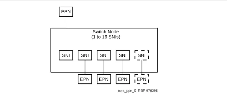
Center Stage Switch (CSS)
Figure 5 shows the CSS linking the PPN to EPNs by the SNI circuit packs in a SN carrier. A SN reduces the amount of interconnect cabling between the PPN and the EPNs by acting as a hub to distribute cabling.
A system using a CSS can connect from 3 to 43 PNs. The CSS can consist of up to 3 SN carriers. The CSS can also consist of 2, 4, or 6 SN carriers (duplicated SNs) in a critical-reliability system.
Each SN contains from 1 to 16 SNI circuit packs. Each interface can connect to a PN or another SN using fiber-optic cable. One interface always connects to the PPN and 1 connects to each EPN.
Figure 5. CSS with Switch Nodes (SNs)
In a high reliability system (with duplicated processor), 2 SNI circuit packs connect to the PPN, allowing up to 15 PNs to connect to 1 SN, up to 20 PNs to connect to 2 SNs, and up to 25 PNs to connect to 3 SNs, depending on the exact configuration chosen.
ATM Port Network Connectivity
(Category A only)
Several Lucent ATM switch types can provide port network connectivity for a DEFINITY ECS. Non-Lucent ATM switches that comply with the ATM standards set by the ITU can also provide DEFINITY ECS port network connectivity. In this configuration, TN2305 multi-mode or TN2306 single-mode ATM circuit packs are installed on the port networks and connected to the ATM switch with the multi- or single-mode fiber specified for the ATM switch.
PPN
SNI SNI SNI SNI SNI Switch Node
(1 to 16 SNIs)
EPN EPN EPN EPN
Architecture
The system consists of 2 main components:
■ The Oryx/Pecos real-time, multiprocessing operating system. Oryx/Pecos supports the SPE.
■ Applications layer, consisting of 3 major subsystems:
— Call processing: starts up and completes calls and manages voice and data in the system.
— Maintenance: detects faults, recovers operations, and performs tests in the system.
— System management: controls the internal processes necessary to install, administer, and maintain the system.
Logical interconnection between system components refers to the 2 kinds of logical links into the SPE:
■ System links for internal system control
■ Application links used by external applications such as adjuncts
DEFINITY ECS Hardware
DEFINITY ECS hardware is covered in detail later in this volume. The following provides only a general overview of type of equipment used in DEFINITY ECS implementations.
Carriers
Carriers hold circuit packs and connect them to power, the TDM bus, and the packet bus. There are 5 types:
■ Control carrier (PPN cabinet only)
■ Optional Duplicated Control Carrier (PPN cabinet only) ■ Optional port carrier (PPN and/or EPN cabinets)
Overview of DEFINITY ECS R8
12 DEFINITY ECS Hardware
Cabinets
The system cabinets house the carriers and all other components, including the power supply. A cabinet contains at least 1 carrier in an enclosed shelf with vertical slots to hold circuit packs. The circuit packs fit into connectors that attach to the rear of the slots. There are 3 cabinet types:
Compact Modular Cabinets (csi)
Overview of DEFINITY ECS R8
14 DEFINITY ECS Hardware
The CMC carrier contains universal port slots. The processor circuit pack resides in slot 1 and the tone-clock circuit pack resides in slot 2 of the A cabinet. The AUX connector on the side of the carrier provides power for 1 attendant console and 1 emergency transfer panel.
Single-Carrier Cabinets (si, r)
Up to 4 Single-Carrier Cabinets (SCC) can be stacked to form a single PN. DEFINITY ECS si supports a stack of up to 3 cabinets. See Figure 7, "Typical Single-Carrier Cabinet".
Single-Carrier Cabinets come in any of 4 configurations:
■ A basic control cabinet that contains a TN790B processor, tone clock, and a power
converter (si model only)
■ An expansion control cabinet that contains additional port circuit packs, interfaces to the PPN, a maintenance interface and a power converter
■ A duplicated control cabinet that contains the same equipment as the basic control cabinet (an SCC cannot be used for duplication on an r model)
■ A port cabinet that contains port circuit packs and a power converter
Figure 7. Typical Single-Carrier Cabinet
Air circulation vents
scdf001 KLC 060597
Circuit packs
Multi-Carrier Cabinets (si, r)
A Multi-Carrier Cabinet (MCC) is a 70 in. (178 cm) cabinet that has up to 5 carriers (see
Figure 8, "Typical Multi-Carrier Cabinet"). The 3 types of Multi-Carrier Cabinets are as follows:
■ PPN cabinet contains the ports, SPE, an interface to an EPN cabinet, and/or a CSS.
■ EPN cabinet contains additional ports, interfaces to the PPN and other EPN cabinets, the maintenance interface, and optional interfaces to other EPN cabinets and/or a switch node (in an SN in a CSS-connected system).
■ Auxiliary cabinet contains equipment used for optional, system-related hardware, such as rack-mount equipment.
Overview of DEFINITY ECS R8
16 Comparing System Versions
Comparing System Versions
To compare the differences between the system version and the carrier version, see
Table 1 and Table 2.
Integrating Adjunct, Peripheral, and
Third-Party Products
The ProductName can work with a wide range of external equipment, applications, and peripherals. It provides extensive support for third-party equipment and applications, such as external ringing equipment and music-on-hold systems. The CallVisor Adjunct-Switch Application Interface (Category A only) gives independent application developers access to DEFINITY ECS features and routing information from within their own applications.
Table 1. System Versions
System PPN Maximum EPNs Connection Method
Release 8csi 1 0 Does not apply
Release 8si 1 2 Direct (fiber only)
Release 8r 1 43 Direct, CSS or ATM
Table 2. Carriers
Carrier Type R8csi R8si R8r
Basic control PPN PPN PPN
Duplicated control Does not apply PPN PPN
Port PPN PPN and EPN PPN and EPN
Expansion control Does not apply EPN EPN
Supported Terminals
■ 300-series attendant consoles (301A, 302A, 302B, 302C)
■ 500-, 2500-, 6200-, 7100-, 8100-, 9100-series analog voice terminals (some 7100 series sets may not be available)
■ 602/603/606 CallMaster sets. The 603 and 606 terminals display the full 8-bit
OPTREX character set of graphical characters, including Eurofonts, and the Japanese katakana character alphabet. (some 602 and 603 CallMaster sets may not be available)
■ The 6400-series 2-wire DCP voice terminals connect to a digital line circuit pack and allow the use of both I-Channels for voice. The number of displayed characters is 27 for calls involving a single ID. If more than one party’s ID displays, the ID truncates to 15 characters.
These terminals also display the full 8-bit OPTREX character set of graphical characters, including Eurofonts, and the Japanese katakana character alphabet.
■ 7300-series hybrid (some sets may not be available)
■ 7400-series DCP voice terminal (some sets may not available)
■ The 8400-series DCP voice terminal connects to a digital line circuit pack and uses one I-channel for voice (the 8411 uses both I-channels). The number of displayed characters for calls involving a single ID is 27. If more than one party’s ID displays, the ID truncates to 15 characters.
This terminal also displays the full 8-bit OPTREX character set of graphical characters, including Eurofonts, and the Japanese katakana character alphabet.
■ The 7500 series and 8500-series ISDN-BRI sets extend the existing ISDN-BRI to allow connection of terminals designed to a variety of BRI specifications.
■ 9000-series cordless sets (TransTalk 9000)
■ The 9400-series DCP terminals 9403B, 9410D, and 9434D display the full 8-bit
OPTREX character set of graphical characters, including Eurofonts, and the Japanese katakana character alphabet. The number of non-United States displayed characters is 27 for calls involving a single ID. If more than one party’s ID displays, the ID truncates to 15 characters.
■ 9601 DEFINITY Wireless Business System terminal
NOTE:
Overview of DEFINITY ECS R8
18 Duplication
IP SoftPhones
IP SoftPhones extend the level of DEFINITY services. They turn a PC or a laptop into an advanced telephone. You can place calls, take calls and handle multiple calls on your PC. There are 4 types of telephones available. They are:
Telecommuter application -- a multifunction station that runs on a PC plus a conventional telephone. Call control is done on the SoftPhone and the voice path is on the DCP set. This IP SoftPhone is intended to be used by home workers who require PSTN quality audio. The MedPro board is not used in this application. Road-warrior application -- a multifunction station that is based entirely on the PC. It is used when there is only a single telephone line available to access the IP network and the DEFINITY. This IP SoftPhone is intended to use by your traveling associates. The MedPro board is used for the road-warrior application.
CentreVu IP Agent -- This SoftPhone is the telecommuter application that has been configured to use the CentreVu IP Agent user interface software. It is used as a Call Center agent station.
Native H.323 -- This is an IP-connected SoftPhone running off-the-shelf H.323 software. It operates as a single-line phone with limited features, which are activated by Feature Access Codes.
Duplication
Duplication is a strategy to create fully redundant systems. Duplication minimizes single failure points that can interrupt call processing. Three system duplication options are available:
■ Standard reliability--this is the only reliability configuration option available for
DEFINITY ECS csi model. Will not duplicate Tone-Clock(s), the Control Carrier or any inter-PN connectivity.
■ Critical reliability--is available with DEFINITY si and r models and requires the full
duplication of the SPE, inter-PN connectivity and the Tone-Clocks (Category A only).
■ ATM Network Duplication--requires full duplication of the inter-PN connectivity and the Tone-Clocks (Category A only).
As duplication increases, the maximum number of port carriers and port circuit packs per cabinet decreases. The information regarding the needed hardware can be found in
Chapter 3.
Administration
A management terminal connects to the system for administrative purposes. Enter commands at the terminal to display administration screens (forms). The forms list data and allow you to add, change, and remove system and voice-terminal features. For system administration information, consult the DEFINITY Enterprise Communications Server Release 8 Administrator’s Guide.
Connecting with TCP/IP Networks
LAN Gateway
With the optional J58890MA-1List 2 LAN Gateway circuit-pack assembly installed, DEFINITY ECS works with PC/LAN-based communications applications that support the CallVisor Adjunct-Switch Application Interface (ASAI) (Category A only).
C-LAN
Overview of DEFINITY ECS R8
20 Connecting with ATM Port Networks (Category A only)
Network Control/Packet Interface
Communicates control channel messages between the processor circuit pack and the distributed network of port circuit packs on the TDM bus. The NetPkt circuit pack (TN794) provides 8 asynchronous data channels that process and route information directly from the processor circuit pack to customer-connected equipment.
PassageWay Integrated
Voice/Data-Workstation Applications
PassageWay applications make the features of the DEFINITY ECS telephone system available from the Windows desktop. With PassageWay and the DEFINITY LAN gateway implemented, a Call Center application could, for instance, let Agents access all
job-related resources—the order-processing database, company World Wide Web site, phone system, voicemail system, and fax machine—from a single interface on the PC.
Connecting with ATM Port Networks
(Category A only)
ATM-PNC (Category A only)
ATM Port Network Connectivity (ATM-PNC) provides an alternative to either the direct connect or Center Stage Switch configurations for connecting the Processor Port Network (PPN) to one or more Expansion Port Networks (EPNs). ATM-PNC replaces the Center Stage Switch in a DEFINITY R8r network with an Asynchronous Transfer Mode (ATM) switch. ATM-PNC is available with all three DEFINITY ECS reliability options— standard, high, and critical.
ATM-PNC integrates delivery of voice, video, and data via ATM over a common large bandwidth LAN, providing reduced infrastructure cost and improved network
manageability. ATM-PNC uses standards-based open interfaces that can be provisioned with either new or existing DEFINITY ECS systems and is ATM-ready for future
ATM-CES (Category A only)
ATM-CES (Circuit-Emulation Service) lets the DEFINITY ECS emulate an ISDN-PRI trunk on an ATM facility. These virtual trunks can serve as integrated access, tandem, or tie trunks. ATM-CES trunk emulation maximizes port network capacities by consolidating trunking. For example, the CES interface can define up to ten virtual circuits for tie-line connectivity, consolidating onto one circuit card network connectivity that usually requires multiple circuit packs.
ATM WAN (Category A only)
ATM Wide Area Network (ATM WAN) extends the Port Network Connectivity (PNC) beyond a single ATM switch. This allows you to use either a private ATM network, public WAN, or a combination of both. Several networked ATM devices can be used as effectively as a single ATM switch for inter-port network connectivity. ATM WAN is supported by the "Multiple Location" feature, where port network cabinets can be administered as separate locations; however, it is not required. You can use multiple ATM switches without multiple locations administered.
EPN
cydfatm2 KLC 102299 ATM
backbone switch
ATM Enterprise
switch Wide
area ATM network
PPN
CES
CES PNC
PNC PPN
Network management platform
ATM Enterprise
Overview of DEFINITY ECS R8
22 IP Solutions (Category A only)
IP Solutions (Category A only)
DEFINITY ECS IP Solutions brings together the flexibility of IP networks with the richness of voice communication. It allows investment protection and optimization in IP, ATM, and PSTN networks. Full applications, features, and management capabilities are carried into the IP environment. Remote workers have full access to communication system features from their PCs. Figure 1 shows the trunk and line connections available with IP Solutions.
NOTE:
Voice quality can and will vary based on LAN conditions, which are extraneous to IP Solutions.
Figure 9. IP Solutions
PSTN
LAN/WAN
cydfipsl EWS 022800 DEFINITY R8
C-LAN C-LAN
C-LAN DS1 MedPro
Mode
TN802B TN802B
IP Trunk Mode
MedPro Mode TN802B
DEFINITY R8
DEFINITY R7
IP Trunk Mode TN802B
TN802B MedPro Mode
DEFINITY IP Softphone or CentreVu IP Agent
Voice Terminal
Telecommuter application
DEFINITY IP Softphone with H.323 voice application
Road-warrior application
H.323 Trunk
As shown in Figure 1, DEFINITY ECS IP Solutions supports IP connectivity for two types of trunks and three types of IP Softphones.
DEFINITY ECS IP Solutions is implemented using the TN802/TN802B IP Interface assembly, which is a Windows NT server that resides on the IP-Interface circuit pack inside the DEFINITY ECS. The TN802B IP Interface, introduced in Release 8, operates in either the IP Trunk mode (for IP trunk connections) or in the MedPro mode (for H.323 trunk connections and H.323 voice processing for IP softphones). The TN802
IP-Interface, introduced in Release 7, operates only in the IP Trunk mode. The TN802B defaults to IP Trunk mode and is backward compatible with Release 7. The MedPro mode requires the new TN799B C-LAN circuit pack.
With Release 7 software, or with Release 8 software configured as Release 7 (that is, R8 used as a bugfix for R7), the TN802B can be used only in the IP Trunk mode. With Release 8 software, the TN802B can be used in either mode but each TN802B can operate in just one of the two modes at a time; that is, all trunks supported by the same TN802B must all be operating in the same mode. DEFINITY ECS supports multiple TN802Bs operating in a mixture of the two modes or a combination of TN802s (operating in the IP Trunk mode) and TN802Bs (operating in either mode).
The IP Trunk and MedPro modes are not interoperable; that is, the TN802B in MedPro mode cannot communicate with another TN802B in IP Trunk mode or with a TN802.
Trunks
DEFINITY ECS IP Solutions supports two trunk configurations:
■ H.323 Trunk
■ IP Trunk
H.323 Trunk
Overview of DEFINITY ECS R8
24 IP Solutions (Category A only)
IP Trunk
In Release 8, the IP Trunk mode will typically be chosen for interoperability with existing TN802 (as opposed to the TN802B) IP Interface circuit packs.
The IP Trunk mode allows trunk groups to be defined as DS1 tie lines between DEFINITY ECS systems over a virtual private network (VPN). Each IP Interface circuit pack in IP Trunk mode provides a basic twelve-port package that can be expanded up to a total of 30 ports.
The benefits of IP Trunk include a reduction in long distance voice and fax expenses, facilitating global communications, providing a full-function network with data and voice convergence and optimizing networks by using the available network resources. Each TN802 or TN802B in IP Trunk mode requires a connection to a modem and an incoming line for Lucent remote access. The TN802 (but not the TN802B in IP Trunk mode) also requires direct access to the NT server on the TN802 hard disk using pcANYWHERE, version 8 or later. A TN802B in the IP Trunk mode does not require the TN799B.
IP Softphones
DEFINITY IP Softphones operate on a PC equipped with Microsoft Windows 95/98/NT and with TCP/IP connectivity to DEFINITY ECS.
DEFINITY IP Solutions supports three IP Softphone configurations:
■ Road-warrior application (voice over IP) ■ Telecommuter application (dual-connection)
Road-warrior application
The road-warrior application of the DEFINITY IP Softphone enables travellers to use the full DEFINITY ECS feature set from temporary remote locations anywhere in the world such as a hotel room. The road-warrior application consists of two software applications running on a PC that is connected to DEFINITY ECS over an IP network. The single network connection between the PC and DEFINITY ECS carries two channels, one for the signaling path and one for the voice path. DEFINITY IP Softphone software handles the call signaling and an H.323 V2-compliant audio application, such as Microsoft NetMeeting, handles the voice communications. The user places and receives calls via the IP Softphone interface on the PC and uses a headset connected to the PC (or the PC’s microphone and speakers) to speak and listen.
With the road-warrior application, NetMeeting has been configured to run in the background and use only the audio portion of the applications. The data collaboration feature of NetMeeting can be used as a stand-alone application but it is disabled during an IP Softphone session.
On DEFINITY ECS, the road-warrior application of the IP Softphone requires the TN799B (C-LAN) for signaling and the TN802B IP Interface circuit pack assembly running in MedPro mode for voice processing. Each VOIP Softphone requires the administration of two stations — an H.323 station and one of the types of DCP station.
Telecommuter application
The telecommuter application of the DEFINITY IP Softphone enables telecommuters to use the full DEFINITY ECS feature set from home. It consists of a PC and a telephone with separate connections to DEFINITY ECS. The PC is connected to DEFINITY ECS over an IP network to provide the signaling path. The PC runs the DEFINITY IP
Softphone software to provide the user interface for call control. A standard telephone is connected to DEFINITY ECS over the public switched telephone network (PSTN) to provide a high-quality voice path. The user places and receives calls via the IP Softphone interface on the PC and uses the telephone handset to speak and listen.
Overview of DEFINITY ECS R8
26 International Requirements
CentreVu IP Agent
The DEFINITY CentreVu IP Agent is a variation of the telecommuter application. The CentreVu IP Agent emulates a Lucent CallMaster set and provides use of the call end capabilities required for Call Center operations from a remote location, such as the agent’s home.
Native H.323
This is an IP-connected softphone running off-the-shelf H.323 software. It operates as a single-line phone with limited features, which are activated by Feature Access Codes.
International Requirements
The DEFINITY system complies with the regulations of many countries and supports a wide range of languages, including user-defined languages. These are a few examples of the country-specific features that are available:
■ Terminal-display language
■ Tone plans and customizable tones (within selected tone plan)
■ Transmission, conference-loss, and tone-loss plans ■ Ringing
■ 12- or 16-kHz periodic pulse metering (PPM) ■ A-Law or µ-Law companding
■ ISDN and non-ISDN, bit-oriented digital protocols ■ Analog, line and trunk port impedances
■ Gain and loss characteristics
■ 1.544-Mbps T1 and CEPT 2.048-Mbps E1 protocols
■ DS1 port administration (DS1 framing, signaling, line coding, and companding on
CEPT trunks).
2 —Site Requirements
This section describes the wall and floor area, and loading specifications for various DEFINITY ECS cabinets.
Floor Area
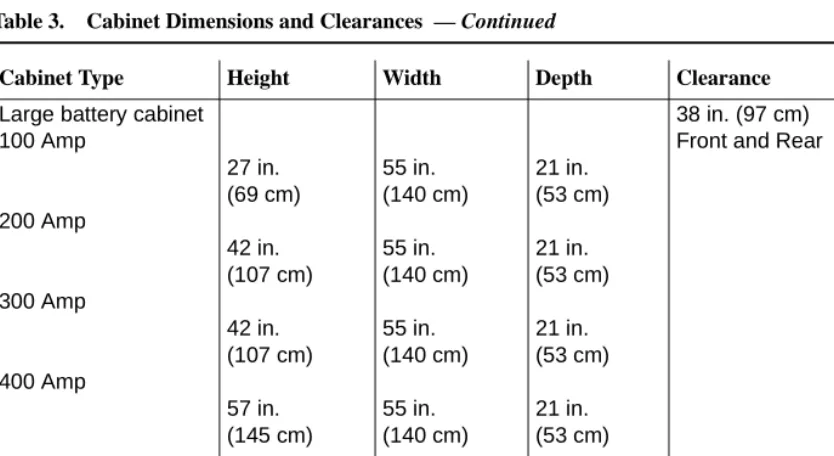
For maintenance access, floor plans typically allocate space around the front, ends, and rear of the cabinets. Floor area requirements vary between cabinets. Dimensions and clearances for all cabinet configurations are listed in Table 3.
Table 3. Cabinet Dimensions and Clearances
Cabinet Type Height Width Depth Clearance
Compact Modular 1-cabinet
2-cabinets
3-cabinets
25.5 in. (64.8 cm) 51 in. (129.6 cm) 76.5 in. (194.4 cm)
24.5 in. (62.2 cm) 24.5 in. (62.2 cm) 24.5 in. (62.2 cm)
12 in. (30.5cm) 12 in. (30.5 cm) 12 in. (30.5 cm)
Left, Right, and Front 12 in. (30.5 cm)
Site Requirements 28 Floor Area Single-Carrier 1-cabinet 2-cabinets 3-cabinets 4-cabinets 20 in. (51 cm) 39 in. (99 cm) 58 in. (1.5 m) 77 in. (2 m) 27 in. (69 cm) 27 in. (69 cm) 27 in. (69 cm) 27 in. (69 cm) 22 in. (56 cm) 22 in. (56 cm) 22 in. (56 cm) 22 in. (56 cm)
38 in. (97 cm) between cabinet and wall
Multi-Carrier1 70 in. (1.8 m)
32 in. (81 cm)
28 in. (71 cm)
Rear 38 in. (97 cm) Front 36 in. (91 cm) Cable slack manager2 7 in.
(18 cm)
32 in. (81 cm)
38 in. (97 cm) DC power cabinet3 20 in.
(51 cm)
27 in. (69 cm)
22 in. (56 cm)
38 in. (97 cm) Front and Rear Table 3. Cabinet Dimensions and Clearances — Continued
Cabinet Type Height Width Depth Clearance
Large battery cabinet 100 Amp
200 Amp
300 Amp
400 Amp
27 in. (69 cm) 42 in. (107 cm) 42 in. (107 cm) 57 in. (145 cm)
55 in. (140 cm) 55 in. (140 cm) 55 in. (140 cm) 55 in. (140 cm)
21 in. (53 cm) 21 in. (53 cm) 21 in. (53 cm) 21 in. (53 cm)
38 in. (97 cm) Front and Rear
1. Includes the auxiliary cabinet, the global AC cabinet, and the global DC cabinet. 2. Used with Multi-Carrier and Single-Carrier cabinets.
3. Requires a floor area of 8 square feet (0.74 square m). Also requires 38 in. (97 cm) between cabinet and wall.
Table 3. Cabinet Dimensions and Clearances — Continued
Cabinet Type Height Width Depth Clearance
Site Requirements
30 Floor Load Requirements
Floor Load Requirements
The equipment room floor must meet the commercial floor loading code of at least 50 lbs. per square foot (242 kg per square meter). Floor plans typically allocate space around the front, ends, and rear (if necessary) of the cabinets, for maintenance access. Additional equipment room floor support may be required if the floor load is greater than 50 lbs. per square foot (242 kg per square meter). See the table below.
Table 4. CabinetWeights and Floor Loadings
Type Weight Floor Loading Remarks
Compact Modular
50 lb. (22.7 kg) Typically wall
mounted—one cabinet can be floor-mounted. Single-Carrier 125 lb. (56 kg) 31 lb./sq. ft. (148.9 kg/m2)
Multi-Carrier 200-800 lb. (90-363 kg) 130 lb./sq. ft. (624.2 kg/m2) Includes Auxiliary, Global AC and Global DC cabinets 100-Amp
battery
400 lb. (181 kg) max. 180 lb./sq. ft. (871.2 kg/m2)
200-Amp battery
815lb. (370 kg) max. 328 lb./sq. ft. (1587.5 kg/m2)
300-Amp battery
1480 lb. (671 kg) max. 476 lb./sq. ft. (2303.8 kg/m2)
400-Amp battery
1580 lb. (717 kg) max. 625 lb./sq. ft. (3025 kg/m2)
Floor-Plan Guidelines
DEFINITY ECS floor plans vary with the size and shape of the equipment room and the extent of future growth. Future growth includes a new or upgraded system, adjuncts and peripherals, and the cross-connect field. See ‘‘Cross-Connect Field’’ on page 41. For floor standing cabinets, reserve the area behind a cabinet for the cross-connect field and the cable slack manager. For wall mounted cabinets, reserve the area beside the cabinets for the cross-connect field. Figure 10 through Figure 15 show typical floor plans. All dimensions are shown in inches. Refer to Table 11 for power requirements.
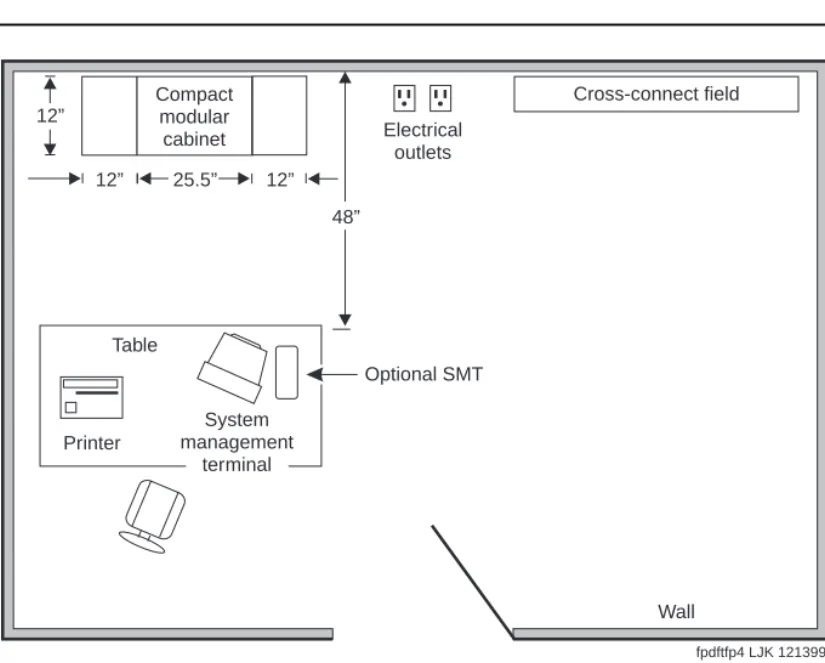
Compact Modular Cabinet (CMC)
Configuration Guidelines
The cross-connect field is either to the rear or right of the cabinet. To allow service access, the table for the management terminal and optional printer is away from the equipment area. See Figure 10 and ‘‘Table Area’’ on page 40 for requirements. In an installation where no cross-connect field is present, an cross-connect field can be installed in the CMC right panel.
The following steps are pre-installation guidelines:
1. Locate the power outlets outside the cross-connect field area. The outlets must not be controlled by a wall switch or be shared with other equipment.
2. Locate the trunk/auxiliary field inside the cross-connect field, if desired. 3. Ground the system. See ‘‘Approved Grounds’’ on page 62.
Site Requirements
32 Floor-Plan Guidelines
Figure 10. Typical Compact Modular Cabinet Floor Plan
NOTE:
To provide power for testing equipment and peripherals, locate electrical outlets at intervals that are in accordance with local codes. Also, ensure that you locate the main shutoff switch near the door in accordance with local codes.
Cross-connect field
Electrical outlets
Table
Printer
System management
terminal
Optional SMT 12”
12” 25.5” 12”
48” Compact
modular cabinet
Wall
Single-Carrier Cabinet Configuration Guidelines
The cross-connect field can be directly behind the cable slack manager. To allow service access, the table for the management terminal and optional printer is away from the equipment area. See Figure 11 and ‘‘Table Area’’ on page 40 for requirements. The following steps are pre-installation guidelines:
1. Locate the power outlets outside the cross-connect field area. The outlets must not be controlled by a wall switch or be shared with other equipment.
2. Locate the trunk/auxiliary field inside the cross-connect field, if desired. 3. Ground the system. See ‘‘Approved Grounds’’ on page 62.
4. For fiber connections between PNs, use a 20-foot (6.1 m) multimode fiber optic cable.
5. Install earthquake protection (if required). See ‘‘Earthquake Protection’’ on page 71.
6. Each cabinet requires either: NEMA 5-15R, NEMA 5-20R receptacle (or equivalent) for United States installations or local
Site Requirements
34 Floor-Plan Guidelines
Figure 11. Typical Single-Carrier Cabinet Floor Plan
NOTE:
To provide power for testing equipment and peripherals, locate electrical outlets at intervals that are in accordance with local codes. Also, ensure that you locate the main shutoff switch near the door in accordance with local codes.
LAN connection
Cross-connect field
Cable slack manager Processor
port network cabinet(s)
(front)
Electrical outlets
Table
Optional SMT
Printer
Wall 38"
22"
32" 27"
System management
terminal
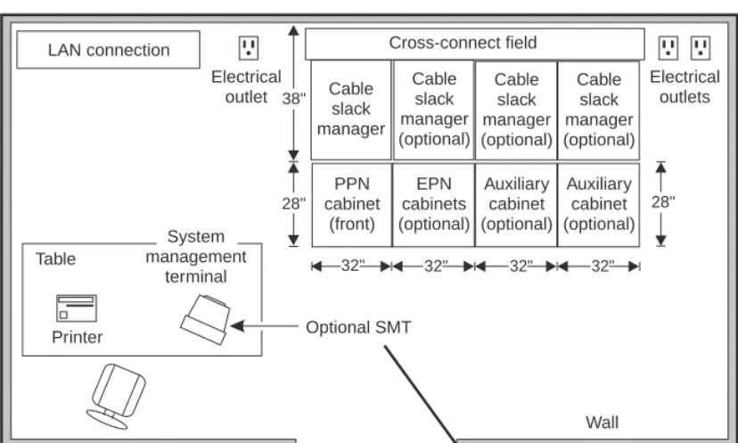
Multi-Carrier Cabinet Configuration
Guidelines
The cross-connect field is directly behind the cable slack manager. To allow service access, the table for the management terminal and optional printer is away from the equipment area. See Figure 12 and ‘‘Table Area’’ on page 40 for requirements. The following steps are pre-installation guidelines:
1. Locate the power outlets outside the cross-connect field area. The outlets must not be controlled by a wall switch or be shared with other equipment.
2. For the PPN cabinets, use either a NEMA 5-50R receptacle (or equivalent) or a NEMA L14-30R receptacle (or equivalent) power outlet or: 220 VAC, 50-60 Hz power outlet for the Global AC Cabinet.
3. For the Auxiliary Cabinet, use a NEMA 5-20R receptacle (or equivalent).
4. Allow at least 3 feet (91.4cm) of space in front of the cabinet to permit the door to open.
5. Ground the system. See ‘‘Approved Grounds’’ on page 62.
6. Install earthquake protection (if required). See ‘‘Earthquake Protection’’ on page 71.
7. Locate the LAN connection field inside the cross-connect field, if desired.
Site Requirements
36 Floor-Plan Guidelines
Figure 12. Typical Multi-Carrier Cabinet Floorplan
NOTE:
To provide power for testing equipment and peripherals, locate electrical outlets at intervals that are in accordance with local codes. Also, ensure that you locate the main shutoff switch near the door in accordance with local codes.
Cross-connect field
Cable slack manager (optional) Cable
slack manager
Port network
cabinet (front)
Auxiliary cabinet (optional)
Electrical outlets Electrical
outlet
Table
Printer
Wall 38"
28" 28"
32" 32"
LAN connection
fpdfmcc1 LJK 121399 System
management terminal
Additional Floor Plans
The following floor plans illustrate recommendations for other possible installations. See
Figure 13, Figure 14, Figure 15, and Figure 16.
Figure 13. Typical Floor Plan with EPN and Auxiliary Cabinet
NOTE:
To provide power for testing equipment and peripherals, locate electrical outlets at intervals that are in accordance with local codes. Also, ensure that you locate the main shutoff switch near the door in accordance with local codes.
LAN connection Cross-connect field
Cable slack manager (optional)
Cable slack manager (optional) Cable
slack manager
PPN cabinet
(front)
EPN cabinet (optional)
Auxiliary cabinet (optional) Electrical
outlet
Table
Printer
Wall 38"
28" 28"
32" 32" 32"
fpdftfp1 LJK 121399 System
management terminal
Site Requirements
38 Floor-Plan Guidelines
Figure 14. Typical Floor Plan with an additional EPN and Auxiliary Cabinets
NOTE:
To provide power for testing equipment and peripherals, locate electrical outlets at intervals that are in accordance with local codes. Also, ensure that you locate the main shutoff switch near the door in accordance with local codes.
LAN connection Cross-connect field
Table Printer Wall 38" 28" Cable slack manager (optional) Cable slack manager PPN cabinet (front) EPN cabinets (optional) 28" 32" Cable slack manager (optional) Auxiliary cabinet (optional) 32" Cable slack manager (optional) Auxiliary cabinet (optional) 32" 32"
Figure 15. Typical Floor Plan with Battery Cabinets
NOTE:
To provide power for testing equipment and peripherals, locate electrical outlets at intervals that are in accordance with local codes. Also, ensure that you locate the main shutoff switch near the door in accordance with local codes.
LAN connection Cross-connect field
Cable slack manager (optional)
Cable slack manager (optional) Cable
slack manager
PPN cabinet
(front)
Battery cabinet (optional)
Battery cabinet (optional) EPN
cabinet (optional)
Auxiliary cabinet (optional) Electrical
outlet
Table
Printer
38"
28" 28"
21" 32" 32"
32"
55" 55"
fpdftfp5 LJK 121399 System
management terminal
Wall
Site Requirements
40 Floor-Plan Guidelines
Figure 16. Typical Floor Plan with ATM Switch (Category A only)
NOTE:
To provide power for testing equipment and peripherals, locate electrical outlets at intervals that are in accordance with local codes. Also, ensure that you locate the main shutoff switch near the door in accordance with local codes.
Table Area
Reserve the table area in the equipment room for the management terminal and optional printer, if so equipped. Terminals require approximately 3.2 square feet (0.3 square m) of area.
LAN connection ATM
switch
Cross-connect field
Cable slack manager (optional)
Cable slack manager (optional) Cable
slack manager
PPN cabinet
(front)
EPN cabinet (optional)
Auxiliary cabinet (optional)
Electrical outlet
Table
Printer
Wall 38"
28" 28"
32" 32" 32"
fpdftfp6 LJK 121399 System
management terminal
Cross-Connect Field
The cross-connect field equipment is located a specified distance from the DEFINITY cabinets and must meet specific requirements. An optional cross-connect field can be installed in the CMC right panel.
For new installations, Lucent Technologies personnel may install the cross-connect field. For more details about the cross-connect field and other site requirements, refer to the following documents:
■ DEFINITY Communications System Generic 1 and Generic 3 Main Distribution Field Design, 555-230-630
■ DEFINITY Communications System Generic 3 Planning and Configuration, 555-230-601
NOTE:
The cross-connect field is wired to the external environment (trunks and lines outside of the building) by telephone company personnel.
Environmental Considerations
This section details the environmental considerations for the Multi-Carrier and
Single-Carrier cabinets. For information about the DEFINITY Wireless Business System, refer to Appendix A.
Heat Dissipation
Site Requirements
42 Environmental Considerations
Altitude and Air Pressure
At altitudes above 5,000 feet (1,525 meters), the maximum short-term temperature limit reduces by 1o Fahrenheit for each 1,000 feet (305 meters) of elevation above 5,000 feet (1,525 meters). For example: at sea level, the maximum short-term temperature limit is 120o F (49o Celsius). At 10,000 feet (3,050 meters), the maximum short-term temperature limit is 115o F (46o C).
The normal operating air pressure range is: 9.4 to 15.2 psi (lbs. per sq. in.) (648 to 1,048 millibars).
Temperature and Humidity
Install the equipment in a well-ventilated area. Maximum equipment performance is achieved at an ambient room temperature between 40 and 120o F (4o and 49o C) for short term operation (not more than 72 consecutive hours or 15 days in a year) and up to 110o F (43o C) for continuous operation.
The relative humidity range is 10 to 95% at up to 84o F (29o C). Above this, maximum relative humidity decreases from 95% down to 32% at 120o F (49o C). Installations outside these limits may reduce system life or affect operation. The recommended temperature and humidity range is 65o to 85o F (18o to 29o C) at 20 to 60% relative humidity. See Table 6.
Table 5. Typical Heat Dissipation for Various Cabinet Configurations
Cabinet type
Number in Stack
With
Terminals? BTUs/Hour
Gram-Cals./
Hour Watts
Compact Modular
1 No 202 810 kg 234
Yes 378 1500 kg 439
Single-Carrier 1 Yes 438 1700 kg 499
4 (max.) Yes 1436 5700 kg 1672
Multi-Carrier 1 No 1058 4200 kg 1232
Yes 1662 6600 kg 1935
Table 6. Temperature and Relative Humidity
Room Temperature (Degrees Fahrenheit)
Room Temperature
(Degrees Celsius) Relative Humidity (%)
40 to 84 4.4 to 28.8 10 to 95
86 30.0 10 to 89
88 31.1 10 to 83
90 32.2 10 to 78
92 33.3 10 to 73
94 34.4 10 to 69
96 35.6 10 to 65
98 36.7 10 to 61
100 37.8 10 to 58
102 38.9 10 to 54
104 40.0 10 to 51
106 41.1 10 to 48
108 42.2 10 to 45
110 43.3 10 to 43
112 44.4 10 to 40
114 45.6 10 to 38
116 46.7 10 to 36
118 47.8 10 to 34
120 48.9 10 to 32
Site Requirements
44 Environmental Considerations
Air Purity
The Compact Modular Cabinet, Single-Carrier and Multi-Carrier Cabinets contain an air filter to reduce particulates flowing through the equipment. Do not install the cabinet where the air may be contaminated by excessive dust, lint, carbon particles, paper fiber contaminants, or metallic contaminants. For example, do not install the cabinet near paper handling equipment such as copiers and high-speed printers, which introduce paper dust and print particles into the environment. Corrosive gases above the levels in
Table 7 must be avoided.
Lighting
Lighting must be bright enough to allow personnel to perform their tasks. The
recommended light intensity is 50 to 70 footcandles (538 to 753 lumens/m2) to meet the Occupational Safety and Health Act (OSHA) standards.
Radio Frequency Noise
Noise is introduced into the system through trunk or station cables, or both. Electromagnetic fields near the system control equipment may cause system noise. Place the system and cable runs in areas where high electromagnetic field strengths do not exist. Radio transmitters (AM or FM), television stations, induction heaters, motors with commutators of 0.25 horsepower (187 watts) or greater, and similar equipment are leading causes of interference.
Table 7. Allowable Concentrations for Atmospheric Contaminants
Contaminant Average Concentration Not to Exceed
All particulate matter 185 micrograms/cubic meter
Nitrate 12 micrograms/cubic meter
Total hydrocarbons equivalent to methane 10 ppm (parts per million)
Sulphur dioxide 0.20 ppm (parts per million)
Oxides of nitrogen 0.30 ppm (parts per million) Total oxidants equivalent to ozone 0.05 ppm (parts per million)
Small tools with universal motors are generally not a problem when they operate on separate power lines. Motors without commutators generally do not cause interference. Field strengths below 1.0 volt per meter are unlikely to cause interference.
Measure weak fields with a tunable meter. Measure field strengths greater than 1.0 volt per meter with a broadband meter.
Estimate field strengths of radio transmitters by dividing the square root of the emitted power in kilowatts by the distance from the antenna in kilometers. This yields the approximate field strength in volts per meter and is relatively accurate for distances greater than about half a wavelength (150 meters for a frequency of 1000 kHz).
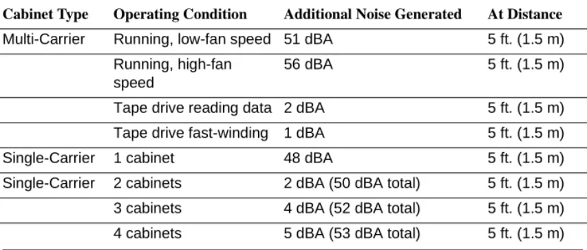
Acoustic Noise Generated by Cabinets
Acoustic noise levels are provided below. In all types of cabinet configurations, if the system cabinet door is open, there is an additional 1 dBA (decibels measured acoustically) of noise. Table 8 lists some typical noise figures for various cabinet combinations.
Table 8. Noise Generated by Cabinets
Cabinet Type Operating Condition Additional Noise Generated At Distance
Multi-Carrier Running, low-fan speed 51 dBA 5 ft. (1.5 m) Running, high-fan
speed
56 dBA 5 ft. (1.5 m)
Tape drive reading data 2 dBA 5 ft. (1.5 m) Tape drive fast-winding 1 dBA 5 ft. (1.5 m)
Single-Carrier 1 cabinet 48 dBA 5 ft. (1.5 m)
Single-Carrier 2 cabinets 2 dBA (50 dBA total) 5 ft. (1.5 m) 3 cabinets 4 dBA (52 dBA total) 5 ft. (1.5 m) 4 cabinets 5 dBA (53 dBA total) 5 ft. (1.5 m)
Site Requirements
46 Environmental Considerations
Electromagnetic Compatibility Standards
This product complies with and conforms to the following EMC standards (as applicable):
■ Limits and Methods of Measurements of Radio Interference Characteristics of Information Technology Equipment, EN55022 (CISPR22), 1993
■ EN50082-1, European Generic Immunity Standard
■ FCC Part 15
■ Australia AS3548
NOTE:
The DEFINITY system conforms to Class A (industrial) equipment. Voice terminals meet Class B requirements.
■ Electrostatic Discharge (ESD) IEC 1000-4-2
■ Radiated radio frequency field IEC 1000-4-3 ■ Electrical Fast Transient IEC 1000-4-4
■ Lightning effects IEC 1000-4-5
■ Conducted radio frequency IEC 1000-4-6
■ Mains frequency magnetic field IEC 1000-4-8 ■ Low frequency mains disturbance IEC 1000-4-11
European Union Standards
Lucent Technologies Business Communications Systems declares that the DEFINITY equipment specified in this document bearing the “CE” mark conforms to the European Union Electromagnetic Compatibility Directives.
The “CE” (Conformité Europeénne) mark indicates conformance to the European Union Electromagnetic Compatibility Directive (89/336/EEC), Low Voltage Directive
The “CE” mark is applied to the following products:
■ Global AC-powered Multicarrier Cabinet (MCC) with 25-Hz and 50-Hz ring generator
■ DC-powered Multicarrier Cabinet (MCC) with 25-Hz ring generator
■ AC-powered Enhanced Single-Carrier Cabinet (ESCC) with 25-Hz ring generator
■ AC-powered Compact Single-Carrier Cabinet (CSCC) with 25-Hz ring generator
■ AC-powered Compact Modular Cabinet (CMC) with 25-Hz and 50-Hz ring generator (for France)
■ Enhanced DC Power System
Cabinet Power Requirements
This section describes cabinet AC- and DC-power source requirements.
AC Power
Power feeders from a dedicated AC-power source (usually located outside the building) connect to an AC-load center. These feeders do not power other equipment. The AC-load center distributes the power to receptacles. The power cord from the AC-power
distribution unit in each multicarrier cabinet and AC-power supply in each single-carrier cabinet plugs into a receptacle.
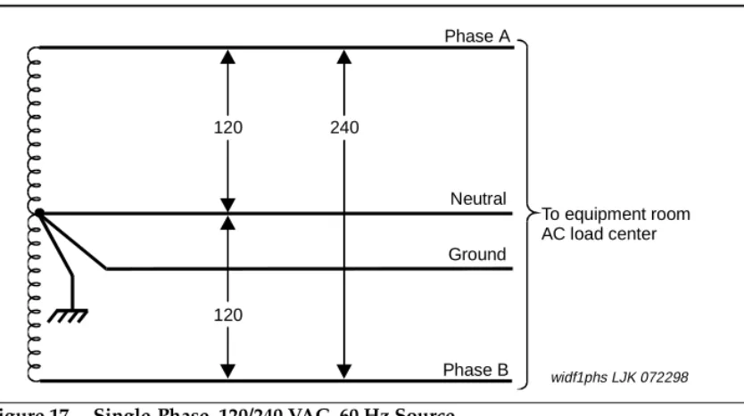
60 Hz Power Sources in R8 Systems
Each of the following power sources can supply 60-Hz power to the AC load in R7 and later systems:
Site Requirements
48 Cabinet Power Requirements
Figure 17. Single-Phase, 120/240 VAC, 60 Hz Source
Figure 18. Three-Phase, 120/208 VAC, 60 Hz Source
120 240
120
Phase A
Ground Neutral
Phase B
To equipment room AC load center
widf1phs LJK 072298
120
208 208 120
120
Neutral Phase A
Phase C Ground Phase B
To equipment room AC load center
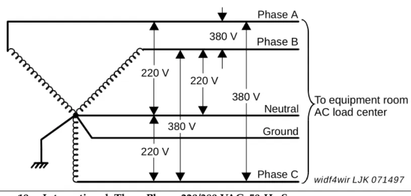
50 Hz Power Sources in R8 Systems
Either of the following power sources can supply 50-Hz power to the AC- load in R7 and later systems:
■ International 5-wire, Y, 220/380 VAC. See Figure 19.
■ International Delta, 3-wire, 220 or 240 VAC. See Figure 20.
NOTE:
The type of power for a Multi-Carrier Cabinet is shown on the cabinet’s rear door, a Single-Carrier Cabinet is shown on the cabinet’s rear cover, and a Compact Modular Cabinet is shown on the right door.
Figure 19. International, Three Phase, 220/380 VAC, 50-Hz Source
220 V
220 V
220 V 380 V
380 V 380 V
Phase A Phase B
Neutral Ground
Phase C
To equipment room AC load center
Site Requirements
50 Cabinet Power Requirements
Figure 20. International Delta, 220 or 240 VAC, 50-Hz Source
Table 9 lists the AC-power sources that can supply power to an AC- load in a cabinet. A NEMA receptacle (or equivalent) connects to the wires from the unit. The AC power cord from the power input of each unit plugs into a receptacle.
Contact your Lucent Technologies representative for the list number of each power source application.
220 V
220/240 V
220 V
Phase A
Phase B
Phase C
To equipment room AC load center
Table 9. Cabinet AC Power Sources
Cabinet Style and Power
Distribution Unit Power Sources Power Input Receptacles
Compact Modular Cabinet AC power supply
(650A)
Single phase 120 VAC with neutral
Single phase 240 VAC with neutral
120 VAC, 60 Hz NEMA 5-15R
240 VAC, 50 Hz IEC 320 Japan installs use country specific receptacles for 100 and 200 VAC, 50/60 Hz
Multi-Carrier Cabinet AC power distribution (J58890CE-1 and J58890CE-2)
Sing