POINT CLOUDS
R
AVIA
NCILP
ERSADA DISSERTATION SUBMITTED TO THE FACULTY OF GRADUATE STUDIES IN PARTIAL FULFILLMENT OF THE REQUIREMENTS FOR THE DEGREE OF
DOCTOR OF PHILOSOPHY
G
RADUATEP
ROGRAMME IN EARTH AND SPACE SCIENCEY
ORKU
NIVERSITYT
ORONTO,
O
NTARIOA
UGUST2017
Abstract
Automatic 3D point cloud alignment is a major research topic in photogrammetry, computer vision and computer graphics. In this research, two keypoint feature matching approaches have been developed and proposed for the automatic alignment of 3D point clouds, which have been acquired from different sensor platforms and are in different 3D conformal coordinate systems.
The first proposed approach is based on 3D keypoint feature matching. First, surface curvature information is utilized for scale-invariant 3D keypoint extraction. Adaptive non-maxima suppression (ANMS) is then applied to retain the most distinct and well-distributed set of keypoints. Afterwards, every keypoint is characterized by a scale, rotation and translation invariant 3D surface descriptor, called the ‘radial geodesic distance-slope histogram’. Similar keypoints descriptors on the source and target datasets are then matched using bipartite graph matching, followed by a modified-RANSAC for outlier removal.
The second proposed method is based on 2D keypoint matching performed on height map images of the 3D point clouds. Height map images are generated by projecting the 3D point clouds onto a planimetric plane. Afterwards, a multi-scale wavelet 2D keypoint detector with ANMS is proposed to extract keypoints on the height maps. Then, a scale, rotation and translation-invariant 2D descriptor referred to as the ‘Gabor, Log-Polar-Rapid Transform’ descriptor is computed for all keypoints. Finally, source and target height map keypoint correspondences are determined using a bi-directional nearest neighbour matching, together with the modified-RANSAC for outlier removal.
Each method is assessed on multi-sensor, urban and non-urban 3D point cloud datasets. Results show that unlike the 3D-based method, the height map-based approach is able to align source and target datasets with differences in point density, point distribution and missing point data. Findings also show that the 3D-based method obtained lower transformation errors and a greater number of correspondences when the source and target have similar point characteristics. The 3D-based approach attained absolute mean alignment differences in the range of 0.23m to 2.81m, whereas the height map approach had a range from 0.17m to 1.21m. These differences meet the proximity requirements of the data characteristics and the further application of fine co-registration approaches.
Acknowledgements
I would like to express the utmost thanks and appreciation to my PhD. supervisor, Dr. Costas Armenakis for his constant support, guidance, patience and mentorship during my time at York University. Under his numerous years of tutelage, I have learnt many things about academics and about life in general. I cannot thank him enough for the opportunity to do so. I’d also like to sincerely thank Dr. Gunho Sohn for his years of support. He and Dr. Armenakis graciously welcomed me into the GeoICT Lab when I first came to Canada. I have thoroughly enjoyed working with and learning from him. I also wish to extend my thanks and appreciation to Dr. Regina Lee, Dr. Burton Ma, Dr. Derek Lichti and Dr. Franz Newland for their valuable time and effort on reviewing this dissertation. I also thank my colleagues at the GEOICT lab with whom I have worked on several interesting research projects over the years.
I would like to sincerely thank Dr. James Elder, Department of Electrical Engineering and Computer Science, York University, for providing the Aeryon Scout UAV video data, and Mike Demuth (Geological Survey of Canada) and Alexander Chichagov (Canada Centre for Mapping and Earth Observation), both from Natural Resources Canada (NRCan) for providing the Columbia Icefield datasets. Teledyne Optech and First Base Solutions are much thanked for providing the urban datasets.
Finally, I dedicate this work to my parents, Sundar and Deokie Persad and thank them for their endless support.
Table of Contents
Abstract ii Acknowledgements iv Table of Contents v List of Tables ix List of Figures xi List of Acronyms xv 1 Introduction 11.1 Initial alignment versus refined alignment ... 4
1.2 Initial alignment: global versus local methods ... 7
1.3 Overview and objectives ... 8
1.4 Contributions ... 10
1.5 Organization ... 11
2 Related Works on Initial Point Cloud Alignment 14
2.1 3D Descriptor-based methods ... 15
2.1.1 3D keypoint extraction ... 15
2.1.2 Matching of 3D keypoints using descriptors ... 18
2.3 2D image-based methods ... 27
2.4 Summary ... 29
3 A 3D-based Approach for Point Cloud Alignment 31
3.1 3D-based Point Cloud Alignment Methodology ... 32
3.2 Extraction of 3D Surface Keypoints ... 34
3.2.1 Scale invariance for 3D keypoints ... 37
3.2.2 Keypoint refinement by adaptive non-maxima suppression ... 41
3.3 3D Surface Descriptors for Keypoints ... 44
3.3.1 Rigid invariance for local 3D descriptors ... 44
3.3.2 Local 3D surface description ... 46
3.3.3 3D Keypoint matching using RGSH descriptor ... 50
3.3.4 Removal of 3D keypoint correspondence outliers ... 51
3.4 Summary ... 54
4 A Height Map-based Approach for Point Cloud Alignment 55
4.1 Height Map-based Point Cloud Alignment Methodology ... 56
4.2 Multi-scale 2D keypoint extraction ... 58
4.2.1 2D keypoint extraction using DTCWT ... 60
4.3 Scale, rotation and translation invariant 2D keypoint descriptor ... 66
4.3.1 Log-polar sampling and mapping for 2D scale and rotation invariance ... 68
4.3.2 Descriptor invariance to 2D cyclic-shifts using the Rapid Transform ... 73
4.3.3 2D keypoint matching using GLP-RT descriptor ... 77
4.4 Summary ... 79
5 Results and Analysis 80
5.1 Results for Method 1: 3D-based Point Cloud Alignment ... 81
5.1.1 Empirical selection of RGSH descriptor bin size ... 82
5.1.2 Case 1: Same sensor datasets, different coordinate systems ... 88
5.1.3 Case 2: Different sensor datasets, different coordinate systems ... 94
5.2 Results for Method 2: Height Map-based Point Cloud Alignment ... 102
5.2.1 Experimental datasets ... 102
5.2.1.1 Dataset 1 (Urban, Loc1) ... 103
5.2.1.2 Dataset 2 (Urban, Loc2) ... 104
5.2.1.3 Dataset 3 (Non-Urban, Loc3) ... 106
5.2.1.4 Tuning and testing datasets ... 107
5.2.2 Empirical tuning: Selection of GLP-RT descriptor parameters ... 108
5.2.2.1 The minimum radius ... 110
5.2.2.2 The maximum radius ... 111
5.2.2.3 The number of rays and number of rings ... 112
5.2.3 Testing experiment: Assessment of the 2D height map approach with other 2D keypoint detectors and descriptors ... 114
5.3 Overall assessment of the proposed 3D-based and height map-based co-
registration methods ... 128
5.3.1 Observations for real datasets 1 and 2 (Urban, Loc1 and Urban, Loc2) .... 129
5.3.2 Observations for real dataset 3 (Non-Urban, Loc3) ... 132
5.4 Computation time ... 134
6 Conclusions 136
6.1 Research outcomes ... 137
6.1.1 Summary of the 3D-based point cloud alignment method... 137
6.1.2 Summary of the Height map-based point cloud alignment method ... 139
6.2 Recommendations for future work ... 140
References 143
Appendix A : Bipartite matching using the Hungarian method 155
Appendix B : Rapid Transform 158
List of Tables
5.1 Manually-defined transformation parameters used for generating target point
clouds of the 4 training sites in the tuning dataset ... 85
5.2 Descriptor matching for various keypoints on Figure 5.4 ... 92
5.3 Co-registration result for ‘Case 1’ Urban dataset ... 93
5.4 Co-registration result for ‘Case 1’ Icefield (Non-Urban) dataset ... 93
5.5 Average Angular and Translation errors for ‘Case 1’ datasets ... 94
5.6 Co-registration result for ‘Case 2’ Urban dataset ... 96
5.7 Co-registration result for ‘Case 2’ Icefield (Non-Urban) dataset ... 96
5.8 Average Angular and Translation errors for ‘Case 2’ datasets ... 98
5.9 Simulated and real source and target datasets which are used for the empirical tuning ... 109
5.10 Simulated and real source and target datasets which are used for the testing experiment ... 109
5.11 Optimal GLP-RT descriptor parameters after tuning ... 112
5.12 Combinations of 2D keypoint detectors and 2D descriptors evaluated on the height map testing datasets ... 116
5.13 Co-registration result for real test dataset 1 (Urban, Loc1) ... 122
5.14 Co-registration result for real test dataset 2 (Urban, Loc2) ... 122
5.15 Co-registration result for real test dataset 3 (Non-Urban, Loc3) ... 123
and GLP-RT descriptor ... 131
5.17 Co-registration errors using proposed surface curvature-based 3D detector and
RGSH descriptor ... 131
5.18 Co-registration errors using 3D-SIFT 3D keypoint detector
and FPFH descriptor ... 131
5.19 Co-registration errors using 3D-SIFT 3D keypoint detector
and SHOT descriptor ... 132
5.20 Comparison of 3D keypoint detectors for ‘real dataset 3’ based on localization
List of Figures
1.1 Illustration of the co-registration problem for 3D point cloud datasets from
multiple sensors ... 2
1.2 Distinction amongst various 3D point cloud alignment (co-registration) approaches ... 5
1.3 Example of two point cloud datasets from different sensors (left: UAV, right: Mobile laser scanner) with varying point characteristics such as different point density, point distribution and point details ... 9
2.1 Different approaches for the initial alignment of 3D point clouds ... 15
2.2 Concept of Spin Image point cloud descriptor formation ... 19
2.3 Concept of FPFH formation showing the triplet angular relation (α, θ, φ) between ps (the keypoint) and pt (neighbouring point) ... 20
2.4 Illustration of the SHOT descriptor ... 21
3.1 Concept of keypoint matching between source and target point clouds ... 33
3.2 Workflow of the proposed 3D-based point cloud co-registration approach ... 35
3.3 Workflow for the proposed 3D keypoint extraction process ... 38
3.4 Concept of obtaining scale-invariant keypoints ... 40
3.5 Example of keypoint extraction on point cloud surfaces. a) Before ANMS b) After ANMS ... 43
3.6 Local keypoint neighbourhood on the surface mesh. Geodesic paths running in radial pattern from keypoint (neighbourhood centroid) to all its neighbouring
points (in black) are shown ... 47
3.7 Illustration of 1-ring mesh neighbourhood around a point ℙ𝑗on the surface mesh and the geometry for obtaining its slope ... 47
3.8 Illustration of the 2D radial geodesic distance-slope histogram (the gray scale shows binning frequency) ... 49
3.9 Example of bipartite graph for keypoint point matching ... 51
4.1 Overview of the height map image point matching approach for co-registering 3D multi-sensor point clouds ... 57
4.2 Scale-space representation of a height map produced by the dual tree complex wavelet transform at three levels of decomposition ... 62
4.3 Keypoint energy maps generated at each of the three decomposition levels ... 64
4.4 Keypoint extraction results. (a) Initial keypoints (before ANMS). (b) Final keypoints (after ANMS) ... 66
4.5 Example of log-polar sampling and mapping ... 70
4.6 Concept of applying Rapid Transform to correct cyclical shift between log-polar descriptors on corresponding keypoints ... 74
4.7 Computation steps of the 1D rapid transform based on the signal flow (or
‘butterfly’) structure when 𝐾 = 8 ... 76
4.8 Concept of bi-directional keypoint descriptor matching showing a successful correspondence (dashed arrows) and an unsuccessful correspondence (solid arrows) ... 78
based point cloud alignment method ... 83
5.2 Icefield (Non-Urban) DSMs used for co-registration experiments to evaluate the proposed 3D-based point cloud alignment method. ... 84
5.3 Recall vs. 1-precision graphs for selecting optimal bin size of the RGSH descriptor across a range of coarse to dense bin resolutions using the DSM tuning dataset ... 87
5.4 Keypoint matching under scaling, rotation and translation ... 90
5.5 Alignment of urban test scene (Urban, Loc2) ... 99
5.6 Alignment of Saskatchewan Glacier test site (Non-Urban, Loc3) ... 100
5.7 Alignment differences between source and target point clouds for ‘Case 2’ datasets. ... 101
5.8 Dataset 1 (Urban, Loc1) used to evaluate the proposed height map-based point cloud alignment method. ... 104
5.9 Dataset 2 (Urban, Loc2) used to evaluate the proposed height map-based point cloud alignment method ... 105
5.10 Dataset 3 (Non-Urban, Loc3) used to evaluate the proposed height map-based point cloud alignment method ... 106
5.11 Recall vs. 1-precision graphs for selecting optimal GLP-RT descriptor parameters using the tuning datasets ... 113
5.12 Recall vs. 1-precision graphs of the six test datasets using different keypoint detectors/descriptor combinations from Table 5.12 ... 116
scale keypoint extraction and GLP-RT descriptor ... 117
5.14 Height map point matching results for real test dataset 2 using proposed multi- scale keypoint extraction and GLP-RT descriptor ... 118
5.15 Height map point matching results for real test dataset 3 using proposed multi- scale keypoint extraction and GLP-RT descriptor ... 119
5.16 Co-registration of point clouds for real test dataset 1 ... 124
5.17 Co-registration of point clouds for real test dataset 2 ... 125
5.18 Co-registration of point clouds for real test dataset 3 ... 126
5.19 Alignment differences between source and target point clouds for the real test datasets ... 127
B.1 Example showing rapid transform on a pair of synthetic images with translation differences ... 158
List of Acronyms
RGSH : Radial Geodesic distance-Slope Histogram GLP-RT: Gabor, Log-Polar-Rapid Transform UAV: Unmanned Aerial Vehicles
LIDAR : Light Detection and Ranging ICP: Iterative Closest Point
PCA: Principal Component Analysis RANSAC: RANdom Sample And Consensus SIFT: Scale Invariant Feature Transform DoG : Difference-of-Gaussian
SURF : Speeded Up Robust Features ISS : Intrinsic Shape Signature MRI: Magnetic Resonance Imaging CT : Computed tomography
FPFH: Fast Point Feature Histograms
SHOT : Signature of Histograms of Orientations TLS : Terrestrial Laser Scanning
MLS: Mobile Laser Scanning ALS : Airborne Laser Scanning
NDT: Normal Distributions Transform 4PCS: 4-Point Congruent Set
SVD: Singular Value Decomposition GPS: Global Positioning System
SPDF: Scale Parameter-Dependent Function KP: Keypoint
ANMS: Adaptive Non-Maxima Suppression NMS : Non-Maxima Suppression
DSID: Dense Scale Invariant Descriptor
DTCWT: Dual Tree Complex Wavelet Transform DWT: Discrete Wavelet Transform
FFT: Fast Fourier Transform RT: Rapid Transform
LP : Log-Polar
DSM: Digital Surface Model RMSE: Root Mean Square Error
AMRE: Absolute Mean Rotational Error AMTE: Absolute Mean Translation Error
ASTER: Advanced Spaceborne Thermal Emission and Reflection Radiometer GDEM: Global Digital Elevation Model
WV-2: WorldView-2 TP: True Positive FP: False Positive
HKS: Heat Kernel Signature
1. Introduction
Automatic alignment (or co-registration) of 3D point clouds is an active area of research in numerous fields of study including photogrammetry, computer vision, laser scanning, 3D modelling and computer graphics. Co-registration is the process of aligning multiple shapes (two or more) in a common coordinate system. It is typically applied to overlapping pairs of 2D images or 3D point cloud models. This research concentrates on addressing the latter issue of automated 3D pairwise point cloud co-registration.
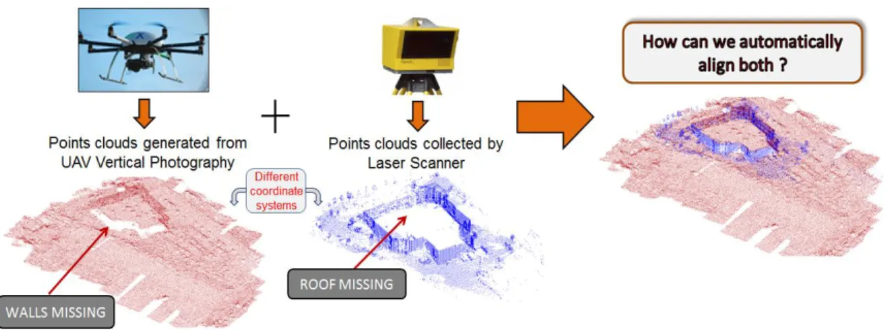
Typical registration tasks usually require the alignment of 3D point clouds that are: i) multi-temporal (i.e., collected at different epochs) and/or ii) acquired from various sensors (e.g., aerial, terrestrial or mobile laser scanners, satellite systems and unmanned aerial vehicles (UAV)) and/or iii) acquired from different viewpoints of the same or similar sensors. More specifically, the co-registration of point cloud datasets is required for 3D surface completion or reconstruction from partially overlapping 3D points located in different coordinate systems (Figure 1.1). Alignment of multi-sensory data has numerous applications in 3D building and terrain modelling, change detection and map-revision in urban and non-urban environments, cultural heritage, crime scene/accident reconstruction, and mapping of open-pit mines.
The co-registration process is based on the mathematical mapping that projects the ‘source’ point cloud to its ‘target’ point cloud. The mathematical mapping is expressed by the transformation relationship (e.g., scale, rotation, translation and shape deformation) between the coordinate systems of the two datasets. Generally, there are
Figure 1.1: Illustration of the co-registration problem for 3D point cloud datasets from multiple sensor platforms.
three categories of 3D coordinate transformations which are commonly utilized for 3D point cloud alignment: i) 3D conformal, ii) 3D rigid, and iii) 3D non-rigid.
The 3D conformal transformation accounts for uniform scale, 3 rotations and 3 translations. The 3D conformal transformation is also referred to as ‘3D similarity transformation’, ‘Helmert transformation’ or ‘7-parameter transformation’ (Andrei, 2006). The 3D rigid transformation estimates 3 rotations and 3 translations. It assumes no scale change between the two datasets. 3D non-rigid transformations such as the affine transformation and spline functions (Jian and Vemuri, 2005) also model the shape deformation between the source and target. There are different types of 3D affine transformation solutions (Lehmann et al., 2014), which vary in terms of the number of estimated transformation parameters, for example: i) 12-parameters (3 rotation angles, 3 translations, 3 skew factors (i.e., shearing along each axis) and different scale factors
along each axis), and ii) 9-parameters (3 rotation angles, 3 translations and different scale factors along each axis).
Traditionally, co-registration is achieved by the manual selection of user-specified corresponding point features, which is then used as input to compute the transformation parameters. However, this is a tedious process particularly when: i) there are a large number of datasets to be co-registered, ii) when datasets contain a large number of points and iii) when the determination of corresponding features is difficult to establish between two point cloud datasets. To overcome these difficulties, an automated process is highly desirable. The challenge in this process includes the automatic extraction and correspondence of the distinct point features. The extraction of point features relates to the automated detection of distinct ‘keypoints’ (e.g., points of sharp topographic variation such as building corners). Correspondence relates to the automatic matching of source keypoints to their corresponding target entities in the 3D space, which are then used to solve for the desired mapping parameters. When there is significant variation between the two point cloud datasets to be aligned, for example, large differences in scale, rotation, translation, and point characteristics (e.g., point density and spatial distribution), it is challenging to establish correct correspondences.
In this dissertation, the source and target point cloud datasets to be aligned differ in terms of a 3D conformal displacement (Equation 1.1) and in terms of point characteristics.
where,
- 𝑠 is the scaling factor,
- 𝑅 is a 3x3 orthogonal rotation matrix formed using the 3 rotation angles (ω , φ , κ) about the x, y and z-axes respectively,
- 𝑇 is a 3x1 translation vector with x, y and z components.
A minimum of three point correspondences are required to determine the scale, rotation and translation 3D conformal parameters. The parameters are commonly estimated through the use of a least squares solution which minimizes the sum of squares of the spatial distances between the source to target point correspondences, thereby estimating the parameters. The solution can be either linear, closed form (Horn, 1987) or non-linear, iterative (Luhmann et al., 2006). Upon estimation of the 3D conformal mapping parameters, the final step for the alignment is to transform the source point clouds into the coordinate system of the target point clouds using Equation 1.1.
1.1
Initial alignment versus refined alignment
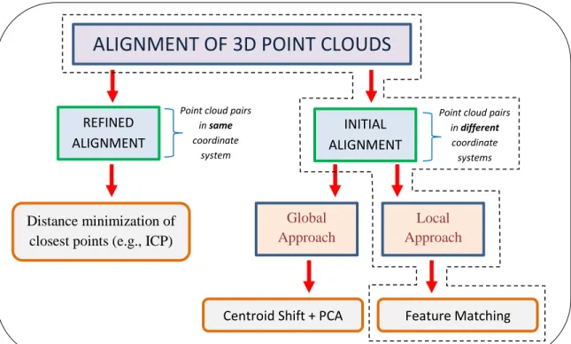
There are two main phases for automated, pairwise 3D point cloud co-registration as illustrated in Figure 1.2: i) the initial alignment, and ii) the refined alignment. The former case handles the co-registration of point cloud datasets in different coordinate systems and there is no proximate matching between the source and target. The latter case assumes that an initial alignment has been applied and there is an existing, approximate
Figure 1.2: Distinction amongst various 3D point cloud alignment (co-registration) approaches (this work concentrates on the framework marked by the dashed outline).
co-registration between the source and target datasets. Both require the computation of a mathematical mapping between two point cloud datasets.
For over two decades, the refined alignment problem has received considerable attention since the development of the influential ‘Iterative Closest Point’ (ICP) algorithm (Besl and McKay, 1992; Chen and Medioni, 1992). Rusinkiewicz and Levoy (2001) provide an overview of many ICP variants. Bouaziz et al. (2013) developed the so-called ‘Sparse ICP’ which is less sensitive to outliers than the classical ICP. In the photogrammetric community, Gruen and Akca (2005) proposed an alternative to the ICP
REFINED ALIGNMENT INITIAL ALIGNMENT Global Approach Local Approach Feature Matching Centroid Shift + PCA
Distance minimization of closest points (e.g., ICP)
ALIGNMENT OF 3D POINT CLOUDS
Point cloud pairs in different coordinate systems Point cloud pairs
in same coordinate
referred to as ‘Least Squares 3D Surface Matching’ (LS3D). Resembling the ICP approach, LS3D also iteratively minimizes the sum of squares of Euclidean distances between two point cloud datasets. However, LS3D differs from ICP in its formulation. ICP computes the transformation parameters using Horn’s linear least squares closed-form solution (Horn, 1987), whereas LS3D uses the Generalized Gauss-Markov nonlinear model. Instead of using the closest point concept for correspondences as done in ICP, Bae and Lichti (2008) developed the ‘Geometric Primitive ICP’ method, which instead uses the point normal vector information together with change in surface curvature for point cloud matching. In more recent times, another class of refinement techniques are ‘non-rigid’ 3D point cloud alignment approaches (Chui and Rangarajan (2003); Lin et al. (2016)). ‘ICP’-based methods assume that the source and target differ in terms of a 3D conformal or 3D rigid transformation. However, ‘non-rigid’ techniques also handles deformation changes between the pairwise point clouds to be co-registered. ‘Refinement-based’ registration methods strongly depend on a very good initial point cloud alignment with sufficient overlap between the source and target. The ‘refinement’ methods do not require an intricate feature-matching step as they are typically based on minimizing the Euclidean distance between the closest points. If the initial alignment is inaccurate, the refinement-based approaches are prone to various mis-registration factors such as local minima solutions and exhaustive searching in the solution space, which negatively affects computational efficiency. Motivated by these issues, this research work concentrates on addressing the initial 3D point cloud co-registration problem.
1.2
Initial alignment: global versus local methods
As shown in Figure 1.2, there are two known primary approaches for initial 3D-to-3D point cloud alignment: i) global techniques and ii) local techniques, (Castellani and Bartoli, 2012). The global-based initial alignment revolves around the use of the principal component analysis (PCA) of the point clouds. The translation can be estimated by the difference in centroids of the source and target data. Then, PCA is used to approximate the rotation required to align the coordinate systems of the source and target point clouds. The global scale factor can be derived based on the ratio of the respective largest distances between the source and target data.On the other hand, local techniques are based on the definition of local surface properties (i.e., descriptors) for automatically detected ‘key geometric features’ on both the source and target point clouds (Note: geometric features can include points, lines, curves or planes). The similarities of the descriptors are then assessed for the determination of corresponding key geometric features. The global co-registration approach suffers when there is partial overlap and/or shape deformation between the source and target surfaces. For instance, the centroids of both shapes may differ due to deformations or when the source and target have different coverage. This affects the estimation of translation parameters. Difference in shape creates similar problems when attempting to estimate scale and rotation parameters. Therefore, it can be argued that the local alignment technique are better suited for co-registering the ‘stable’ parts of the point cloud surfaces, for instance, when dealing with natural terrain datasets which may have undergone deformation, for example, landslides, flow of glaciers, etc.
1.3
Overview and objectives
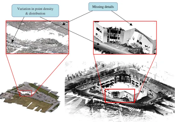
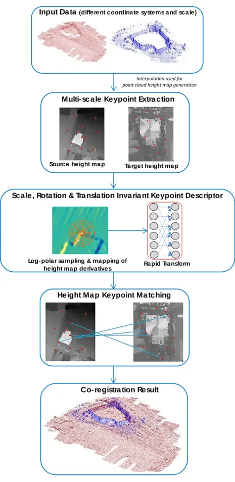
3D point clouds have varying characteristics and be represented in various ways. They are represented in 3D or 2D formats such as: i) as raw 3D points, or as ii) interpolated, 2D height (or depth) map raster images. As shown in Figure 1.3, source and target point cloud datasets can also differ in terms of characteristics such as: i) point density (e.g., dense versus sparse point spacing), ii) point distribution (e.g., regular, gridded points versus irregular, non-gridded points), and iii) missing point data (i.e., data gaps/holes), possibly caused by occlusions or by different sensor viewpoint perspectives during data acquisition. To handle these different cases (i.e., differences in data representation and characteristics) two independent approaches for the automatic co-registration of point clouds in different 3D conformal coordinate systems are investigated and explored. Both of the implemented methods are local alignment type techniques which follow an automated feature matching pipeline that includes three main phases: i) feature extraction, ii) feature description and iii) feature correspondence. The proposed methods are based on extracting and matching distinct point landmarks, i.e., keypoints on the source and target point clouds.
Although both proposed approaches adopt a similar feature matching workflow, their inherent individual components are unique, i.e., the techniques used for keypoint extraction, keypoint descriptor formation and keypoint matching are different. This stems from the two different ways in which the point clouds can be represented, i.e., either as 3D points or as interpolated, height map 2D raster images.
Figure 1.3: Example of two point cloud datasets from different sensors (left: UAV, right: Mobile laser scanner) with varying point characteristics such as different point density,
point distribution and point details.
In the first proposed approach, feature matching is performed entirely in the original 3D point cloud space, whilst in the second method, the feature matching process is applied to the planimetric, height map projection (i.e., 2D image representation) of the 3D point clouds. For the latter, even though feature matching is performed in the 2D domain, the resulting matched points also have an associated Z or depth component, thereby facilitating 3D to 3D co-registration. The objectives of this dissertation are:
Missing details
details Variation in point density
i) To develop a 3D-based feature matching approach for co-registering 3D point clouds in different 3D conformal coordinate systems.
ii) To develop a height map-based feature matching approach for co-registering 3D point clouds in different 3D conformal coordinate systems.
iii) To individually evaluate the experimental findings of each approach on urban and non-urban datasets with different point cloud characteristics.
iv) To assess the performance of both methods relative to each other, as well as with existing, state-of-the-art approaches.
1.4
Contributions
This research work contributes to the alignment of 3D point clouds in the geomatics fields of photogrammetry, remote sensing, laser-scanning and geographic information systems and incorporates multi-sensor and multi-temporal, urban and non-urban datasets. In this section, the main contributions in each of the two proposed 3D point cloud alignment methods are listed.
The contributions in the 3D-based co-registration method are:
The development of a scale-invariant 3D keypoint feature extraction method using morphological properties, specifically the local surface curvature.
The development of a scale, rotation and translation invariant 3D keypoint surface descriptor referred to as the radial geodesic distance-slope histogram (RGSH).
The use of bipartite graph descriptor matching for establishing 3D keypoint feature correspondences without the need for user-specified thresholds. A threshold-free, RANSAC outlier detection algorithm is then used to filter incorrect keypoint correspondences (i.e., outliers).
The contributions in the Height map-based co-registration method are:
The development of a multi-scale, wavelet-based 2D keypoint extraction method on the height map image representations of the 3D point clouds.
The development of a scale, rotation and translation invariant 2D keypoint descriptor referred to as the Gabor, Log-Polar-Rapid Transform (GLP-RT) descriptor.
The use of bi-directional, nearest neighbour descriptor matching for establishing height map keypoint correspondences, without the need for user-specified thresholds.
1.5
Organization
The remaining chapters in this dissertation are organized as follows:
Chapter 2: A literature review of relevant works related to initial 3D point cloud alignment techniques is discussed. These include a survey of: i) 3D descriptor-based
point cloud registration methods, ii) 3D non-descriptor-based point cloud co-registration methods and iii) 2D-image based point cloud co-co-registration methods.
Chapter 3: This chapter covers the proposed 3D-based point cloud alignment approach. An automated 3D feature matching approach is presented. This is achieved by extracting scale-invariant 3D keypoints and generating their 3D local surface descriptors. To match the 3D keypoints, a one-to-one correspondence approach based on bipartite graphs is used. To filter outliers (i.e., incorrect keypoint correspondences), a threshold-free modified-RANSAC is applied. Finally, the 3D conformal transformation parameters are determined using the established correspondences.
Chapter 4: The second proposed height map-based automated approach for 3D point cloud alignment is detailed in this chapter. Unlike the first method, whose feature matching process is implemented entirely in the 3D domain, this approach instead uses 2D height map images of the 3D point clouds to find correspondences. Prior to co-registration, source and target height map images are generated directly from the source and target 3D point cloud datasets respectively. This is achieved by projecting and interpolating the 3D point cloud dataset onto the x,y-plane. Afterwards, 2D keypoints are extracted on both height map image pairs using a multi-scale wavelet technique. This is followed by generation of scale, rotation and translation-invariant 2D keypoint descriptors. Source and target descriptors are matched using a bi-directional nearest neighbour search in the feature space. Then, the modified-RANSAC developed in
Chapter 3 is applied to remove keypoint correspondence outliers. Finally, the 3D conformal transformation parameters are determined using the established correspondences.
Chapter 5: This chapter presents experimental results for each of the two proposed co-registration approaches. The methods are evaluated through comparisons with reference data, reference 3D conformal transformation parameters. Experiments are also carried out to directly evaluate the performance of both proposed methods with each other, as well as with existing state-of-the-art 3D point cloud co-registration approaches.
Chapter 6: A summary of the contributions and research findings are outlined in this chapter. Also discussed are suggestions for future work and potential improvements.
2. Related Works on Initial Point
Cloud Alignment
This chapter provides an overview of existing work related to the initial 3D point cloud alignment problem. In particular, a review of methods used for solving initial 3D point cloud co-registration is discussed from Sections 2.1 to 2.3.
Automatic estimation of scale and the six 3D rigid parameters between point clouds is a challenging problem. For initial point cloud alignment, it is assumed that there is no prior knowledge of the 3D conformal transformation parameters (i.e., single global scale factor, 3D rotation angles and 3D translations). However, in some of the reviewed literature, the scale factor is assumed to be known and only the six rigid parameters are considered as the unknowns to be computed. Instances of such cases for the reviewed literature will be identified in this chapter. If scale is assumed to be known, the matching (or correspondence) problem is greatly simplified, since geometric elements such as lengths, distance between features and surface area can all be utilized to find correspondences.
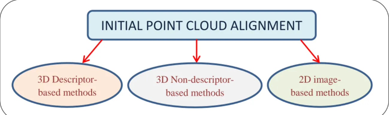
There are various approaches one can apply to achieve initial source to target 3D point cloud co-registration. These can be classified into three categories (Figure 2.1): i) 3D descriptor-based methods, ii) 3D non-descriptor-based- methods and iii) 2D image-based methods. There are three general steps to solve the alignment problem: detection/extraction of key geometric features, matching/correspondence of these features
Figure 2.1: Different approaches for the initial alignment of 3D point clouds.
and assessment of the correspondences. These tasks are explicit or implicit depending on the co-registration approach utilized.
2.1 3D Descriptor-based methods
2.1.1 3D keypoint extraction
Descriptor-based methods are typically applied in 3D feature matching workflows. They usually rely on the extraction of salient key-features (e.g., 3D keypoints) on the point cloud surface. For these keypoints, descriptors are formed by utilizing various types of local neighbourhood shape attributes of the point cloud. Similar descriptors on source and target point clouds can then be matched using a similarity cost function to find corresponding keypoints.
Interest points or keypoints are well utilized for matching and registration problems in various 2D image-processing applications such as object recognition (Lowe, 1999; Azad
INITIAL POINT CLOUD ALIGNMENT
3D Descriptor-based methods 3D Non-descriptor-based methods 2D image-based methods
et al., 2009) and scene reconstruction (Hartley and Zisserman, 2000). Keypoint detectors can be regarded either as: i) a fixed scale detector, where the user has to manually define a local neighbourhood around a candidate point to perform the required checks for keypoint detection, or ii) a scale-invariant detector, where the local scale (i.e., local neighbourhood of interest) around a keypoint is automatically defined by the algorithm. The concept of scale invariance is that the attribute or features of an object should not change when the object is scaled by a multiplicative factor. The definition of a similar local scale for a corresponding source and target keypoint is important since it ensures that they both have the same local neighbourhood regions, which can then be used for computing comparable keypoint descriptors (or attributes). Scale-invariant detectors are typically used for this purpose.
Automated scale selection mechanisms have been popularly applied for 2D keypoint detectors. Examples include the Scale Invariant Feature Transform (SIFT) detector (Lowe, 2004), which uses a ‘Difference-of-Gaussian’ (DoG) framework for estimating the local scale, whereas another detector, i.e., the Harris-Laplacian interest point operator (Mikolajczyk and Schmid, 2004) uses Lindeberg’s automatic scale selection approach (Lindeberg, 1998). The DoG approach smoothes the data with Gaussian kernels of differing standard deviations and then takes the difference of smoothed outputs to build a scale-space representation. The details of Lindeberg’s approach will be discussed in Chapter 3.
With the increasing use of point clouds for 3D object recognition and matching (Lai and Fox, 2010; Tam et al., 2013), there are numerous 3D keypoint detectors including the
intrinsic shape signature (ISS) (Zhong, 2009), the mesh-Difference of Gaussians (mesh-DoG) (Zaharescu et al., 2009), Heat Kernel Signature (HKS) (Sun et al., 2009) and Harris 3D (Sipiran and Bustos 2011). ISS is a fixed scale detector. ISS uses the ratios of the eigenvalues of the local neighbourhood to determine surface variation. Points with large surface variations are marked as keypoints. The mesh-DoG, HKS and Harris 3D detectors operate on mesh representations of the point clouds. The mesh-DoG is a scale-invariant detector which uses a DoG-based scale-space representation. For mesh-DoG, the ratios of eigenvalues from the Hessian matrix of the local mesh neighbourhood are used for keypoint definition. The HKS is related to the surface curvature of a point and is based on the diffusion of heat on a surface mesh using the Laplace-Beltrami operator. This operator is extensively used in 3D shape analysis to describe physical processes such as heat diffusion and wave propagation (Wetzler et al., 2013). Keypoints are determined by searching for local maxima HKSs across the surface mesh (Teran and Mordohai). HKS is not a scale-invariant detector, however, Bronstein and Kokkinos (2010) have presented an approach to address this problem. Harris 3D is a fixed scale detector. It fits a local surface quadratic patch to the point data and computes the so-called ‘Harris-response’ (Harris and Stephens, 1988) for each mesh vertex. Query vertices with large responses are classified as keypoints.
ISS, mesh-DoG, HKS and Harris 3D are examples of detectors which utilize surface geometry for the extraction of 3D keypoints. There are also volume-based methods which utilize 3D voxel representations instead of direct point cloud data for keypoint detection (Yu et al., 2013). These include a 3D extension of the SIFT method (Rusu and Cousins,
2011; Hänsch et al., 2014). 3D-SIFT is scale-invariant and utilizes a ‘Difference-of-Gaussian’ scale-space approach, where a series of downsampling/smoothing is applied to the point data to determine keypoints and their local scale. 3D-SIFT encompasses both keypoint detection, as well as keypoint description (Section 2.1.2). Volume-based approaches operate on voxel representations of the 3D model, whereas surface geometry-based methods use geometric attributes from surface patches, normals or contours of the 3D point clouds.
2.1.2 Matching of 3D keypoints using descriptors
Following the extraction phase, attributes (or descriptors) must be assigned to the keypoints. Then a search strategy is employed to find keypoint descriptors with high similarities. The generation of uniquely discriminable descriptors is an important step since it influences the keypoint matching success rate. Descriptors can be represented in various forms including: 1D vectors, 2D / 3D histograms or multi-dimensional arrays. Volume-based 3D keypoint descriptors such as the 3D-SIFT implementations have been used for video sequences and 3D medical images (e.g., MRI and CT scans) (Scovanner et al., 2007; Flitton et al., 2010). In these cases, the 3D data is first converted into a 3D array of voxels containing data points and the descriptor is generated based on the gradient magnitude and orientation of these voxels.
There has also been various surface geometry 3D point cloud descriptors developed over the years. Some of these include the Spin Images (Johnson and Hebert, 1999), Fast Point Feature Histograms (FPFH) (Rusu et al., 2009) and Signature of Histograms of
Orientations (SHOT) (Tombari et al., 2010). The HKS described in the previous section can also be used as a descriptor for surface keypoints (Section 2.1.1).
For Spin Images (Figure 2.2), every point within the local keypoint neighbourhood are assigned two coordinates, α and β ; α is the distance from the keypoint to the projection of the neighbourhood point on the local surface tangent plane (i.e., the plane tangent to the normal vector of the keypoint). β is the distance from the neighbourhood point to the local tangent plane. For every point in the local neighbourhood, these pair of coordinates is accumulated into a 2D array, thus forming the descriptor.
Point Clouds Spin Image coordinate system
Figure 2.2: Concept of Spin Image point cloud descriptor formation. Left: Keypoint (red point) with its normal vector N and tangent plane to this vector (blue region). Right: Coordinate system of spin image where the coordinate pair (α, β) is defined by
the vector projecting from the keypoint (red point) to a neighbouring point cloud (yellow point). (Modified after: Ruiz-Correa et al., 2004)
FPFH is a histogram-based descriptor which bins three angular attributes defined by the relation between every neighbourhood point and the keypoint (Figure 2.3). SHOT is also a histogram-based descriptor which defines a spherical neighbourhood around the
Figure 2.3: Concept of FPFH formation showing the triplet angular relation (α, θ, φ)
between ps (the keypoint) and pt (neighbouring point). The u,v and w vectors defines a
local coordinate frame of the point cloud and is computed using the normal vector of the keypoint. (From: Rusu, 2009).
keypoint (Figure 2.4). This spherical neighbourhood is then partitioned into spherical grid sectors. For each grid sector, the angles between the normals at the neighbouring points and the normal at the keypoint are accumulated into a local histogram. The local histograms of all grid sectors are then concatenated to form the SHOT descriptor.
Geometry-based descriptors such as Spin Images, FPFH and SHOT require a local point cloud neighbourhood to be defined around the keypoint. A user-specified distance
can be applied to define local neighbourhoods when the source and target point clouds have the same scale. However, in situations where there is a scale difference between the source and target datasets, the descriptors are not scale-invariant and will fail during the feature matching process. As discussed earlier, scale-invariance is typically provided by local keypoint scales estimated from a front-end detector. Mellado et al. (2016) developed an approach for scale-invariant co-registration of multi-sensor point clouds based on a descriptor known as ‘Growing Least Squares’ (GLS). The GLS descriptor is built in a logarithmic scale space by fitting algebraic spheres on the point cloud data.
Figure 2.4: Illustration of the SHOT descriptor. It is based on the partitioning of sectors within a spherical grid structure around the keypoint. (From: Tombari et al., 2010).
Descriptor-based matching usually comprises of three main components: i) the design of a cost (or similarity) function to assess the similarities of source and target keypoint descriptors, ii) a searching mechanism to efficiently compare the descriptors in their feature space (i.e., 1D, 2D, 3D or multi-dimensional feature space) for establishing
one-to-one keypoint correspondences and iii) an approach to filter false (or outlier) keypoint matches.
Weber et al. (2015) developed a descriptor-based point-matching framework to automatically align surface point clouds collected from a Microsoft Kinect sensor. The method fuses multiple Kinect-based point clouds of an object or scene. Their approach uses the FPFH point cloud descriptor and does not extract points of interest or keypoints. Instead, the descriptors are computed for every point cloud in the dataset. The local point cloud neighbourhood used to compute the surface descriptors are defined by a user-specified radius value. This indicates that the approach is not scale-invariant as the same radius value is applied on both source and target point clouds. Thus, the approach is unable to handle cases where the point clouds to be co-registered differ by a global scale factor. The descriptor-based point matching is determined using the nearest neighbour distance ratio (NNDR) (Szeliski, 2010) followed by the RANdom SAmple Consensus (RANSAC) (Fischler and Bolles, 1981) for removal of correspondence outliers. The combination of NNDR and RANSAC is a popular strategy for matching keypoints using descriptors.
NNDR is based on searching for the target keypoint that is the ‘nearest neighbour’ for a source keypoint within the descriptor feature space. The nearest neighbour is the target keypoint with the minimum Euclidean distance to the source keypoint in the feature space. In this case, the Euclidean distance metric is the similarity (or cost) function. Efficient nearest neighbour searching is typically achieved using k-d trees (Bentley, 1975)
It is possible that 1st and 2nd nearest neighbour target matches have similar distances to the source keypoint. NNDR compares the ratio of these two distances. A distance ratio that tends to 1 indicates matching ambiguity and thus the source keypoint should not be included in the final set of correspondences. RANSAC is used to further filter wrong matches. It is based on randomly sampling the minimum number of correspondences required to compute the transformation parameters. Then all the source keypoints are back-projected onto the target domain using these parameters. Matches are then established by searching for source to target keypoints which are in close proximity to each other based on a threshold. The number of correspondences are then recorded. RANSAC is iterative and the final set of matches is the sample set which gives the highest amount of correspondences. The disadvantage of utilizing both the NNDR and RANSAC is that user-defined thresholds are required to filter potentially incorrect point matches. If there is no information about the coordinate systems of the source and target point clouds prior to matching, it becomes difficult to determine optimal threshold values without some empirical analysis.
Zeng et al. (2016) proposed a 3D local volumetric patch descriptor algorithm referred to as ‘3DMatch’. The approach is based on deep learning which requires training the descriptors on large volumes of data. This can be time-consuming and also depends on the availability of training data.
2.2 3D Non-descriptor-based methods
There are also descriptor-free approaches which address the initial 3D point cloud alignment problem based on the data and data-derived geometric primitives. A common approach for global co-registration is the utilization of PCA or SVD (Singular Value Decomposition). PCA (or SVD) is used to approximate the rotation required to align the coordinate systems of the source and target point clouds. The translation can be estimated by the difference in centroids of the source and target data. However, when there is partial overlap and/or shape deformation between the source and target surfaces this approach does not provide the correct transformation parameters (Salvi et al., 2007; Castellani and Bartoli, 2012).
Other non-descriptor based methods utilize various geometric constraints and relationships amongst points, lines or planes. In terms of the plane-based methods, von Hansen (2006) presented a framework for terrestrial laser scanning (TLS) co-registration. Firstly, planes are extracted from point cloud data and this is followed by an exhaustive search for corresponding planes. The method does not cater for scale differences between the point clouds. Brenner et al. (2008) derived two methods for the initial co-registration of TLS data: a plane-based scoring approach and another which uses the normal distributions transform (NDT) (Biber, 2003). In the first method, plane triplet correspondences are scored using the similarity of their normal vector directions, in combination with distances to the plane origin. The second method sliced the 3D scans into 2D layers, and then used the 2D NDT algorithm for co-registration. NDT is an optimization-based co-registration algorithm which tries to maximize a probabilistic
matching score between two 2D scans. Only the 3D roto-translational parameters were accounted for in their work.
Stamos and Leordeanu (2004) used both linear and planar features to align laser scans of buildings. Properties such as length of the lines, in addition to plane sizes were used to discard possible erroneous matches, thus reducing the combinatorial correspondence search space. This was accomplished using a variety of heuristically set thresholds. Their method solved for the six rigid parameters. Yang et al. (2016) used semantic features from urban scenes for automated TLS co-registration. The point cloud data was segmented into ground and non-ground followed by the extraction of vertical linear features. The vertical features were then triangulated to form a network. Then a hashing table with triangular constraints were used to find matching source and target triangles. The method used various Euclidean distance-based constraints and thresholds which can only be applied when source and target point clouds are of the same scale. A geometric object approach was proposed by Chan et al. (2016) where a single, octagonal lamp pole was used for the alignment of terrestrial laser scans in different coordinate systems (i.e., different 3D position and orientation). The premise of the approach is to fit an octagonal pyramid model to the raw point clouds. Then, virtual points from the lamp pole structure are computed and used within an iterative matching strategy to estimate the registration parameters.
Linear features extracted from point clouds have been used to match Airborne Laser Scanning (ALS) and TLS data (von Hansen et al., 2008). This method sequentially computed the 3D rotation and translation parameters. Rotation was derived via the
correlation of line orientation histograms. Afterwards, translation was determined using a ‘generate and test’ scheme, where the quality of all line correspondence combinations are assessed using the proximity of matching between ALS and TLS line midpoints. Yang et al. (2015) presented an approach for ALS to TLS alignment in urban scenes. They employed a spectral graph correspondence approach for matching building outlines. The graph matching utilized scale-variant geometric constraints such as distances together with several other spatial relations derived from the TLS and ALS building outlines. Urban areas typically contain many other rich descriptive details such as road networks, street furniture and vegetation. Therefore, the method may falter in urban datasets where there is a lack of building structures.
Aiger (2008) developed the ‘4-Point Congruent Set’ (4PCS) method for initial rigid alignment of point clouds. The approach begins by sampling four-point coplanar tuples from the source point cloud, followed by a search based on an affine ratio to find corresponding four-point tuples in the target point cloud. The best transformation is then selected from multiple candidate transformations formed by the set of matching quad- ruples. There have been several extensions/variations of 4PCS. Theiler et al. (2014) combined 3D keypoints with the 4PCS for the alignment of terrestrial laser scans. In other work, Mellado et al. (2014) developed a speeded up version of 4PCS. In context of full initial registration (i.e., solving for scale and rigid parameters), Corsini et al. (2013) presented an extension of 4PCS which can handle scale changes between datasets.
Yang et al. (2013) developed an ICP method referred to as ‘Globally Optimal ICP’. This ICP approach does not require any initial alignment and is based on a branch and
bound optimization search for optimal registration parameters. However, as mentioned in Theiler et al. (2014), the globally-optimized ICP is not efficient when applied to large scale data such as laser scans.
In comparison to non-descriptor based methods, descriptor-dependent approaches take into account local data information, i.e., it considers neighbouring elements for attribute definition. Descriptor-based methods provide semantic context, thus strengthening the matching process with richer information about the local keyfeatures (for example, enabling the elimination of false matches by comparing descriptor similarity).
2.3 2D image-based methods
Another active branch of research which addresses initial point cloud alignment are image-based approaches. The concept revolves around the utilization of image-based representations of the point cloud data collected from various sensor acquisition systems. One type of image representation can be obtained from optical cameras which are mounted to and synchronised with the laser scanners during point cloud data collection. If the transformation between the camera coordinate system and the laser scanning system is established prior to data collection, then the relative orientation of an image pair can be used to derive the transformation parameters between the associated source and target laser scans. Image representations can also be 2D reflectance intensity images formed from the energy of the backscattered laser light on a laser scanning system. Another type of image representation are 2D height maps or range images. The pixels of height maps store the 3D coordinates of a point cloud. Usually each height map image pixel is a
visualization of the point cloud surface elevation. However, depending on the application, the other axes directions of the point cloud’s 3D coordinate system can also be used to project the point clouds into the 2D height map/range image domain.
Manasir and Fraser (2006) used the relative orientation of optical image pairs to co-register multiple TLS datasets. However, a significant amount of work instead focuses on TLS point cloud co-registration using reflectance intensity images (Böhm and Becker, 2007; Wang and Brenner, 2008; Kang et al., 2009; Weinmann et al., 2011). These works all follow a similar alignment framework based on 2D keypoint matching between reflectance image pairs.
Various interest point operators can be used for extracting 2D keypoints including the Förstner operator (Förstner and Gülch, 1987), and Moravec and Harris corner detectors (Moravec, 1980; Harris and Stephens 1988). 2D descriptors such as SIFT (Lowe, 2004) and Speeded Up Robust Features (SURF) (Bay et al., 2008) can then be used for matching the 2D keypoints. The SURF descriptor is based on the computation of Haar wavelet filter statistics in both the horizontal and vertical image directions.
The matched 2D feature points from the intensity images also have accompanying 3D point cloud coordinates, therefore 3D transformations can be directly computed for 3D point cloud co-registration. A common trend in these works is the usage of Lowe’s SIFT keypoint detector and descriptor algorithm coupled with RANSAC. This due to the scale and rotation invariance properties of SIFT. SIFT has also been applied to match 2D keypoints on range images for the purposes of 3D point cloud alignment (Barnea and Filin, 2007; Sehgal et al., 2010).
Barnea and Filin (2008) proposed a combinatorial keypoint approach for terrestrial point cloud matching using panoramic range images. Range image keypoints are extracted using a so-called ‘min-max’ interest point detector. These keypoints are then subjected to RANSAC. Firstly, a triplet of keypoints is randomly selected. Then differences in 3D Euclidean distances between source and target keypoint pairs from the sample set are used as a check for the verification step within RANSAC. For multi-sensor point clouds which may have scale differences, this verification check will not suffice. Additionally, depending on the amount of keypoints extracted from scene to scene, the correspondence search space can significantly increase and be time consuming.
Novák and Schindler (2013) used height maps for the co-registration of 3D laser scanning and photogrammetric point clouds. Point clouds are firstly converted to height maps by projecting onto a planimetric x, y-plane. Then gradient information and RANSAC are used to match points on source and target height maps. Afterwards, ICP is applied to refine the 3D point cloud registration accuracy.
2.4 Summary
From the reviewed literature, a considerable amount of 3D approaches (both descriptor and non-descriptor based methods) are not scale-invariant and only consider the estimation of 3D rigid transformation parameters. This work addresses the alignment of 3D point clouds which differ in terms of a 3D conformal transformation. In Chapter 3, a modified approach of Lindeberg’s local scale selection mechanism (Lindeberg, 1998) for scale invariant extraction of 3D surface keypoints is proposed.
In terms of 3D descriptors, most current methods utilize geometric relations (e.g., angles) between the 3D points. The proposed 3D descriptor uses surface morphology characteristics for the local neighbouring region around the keypoints.
From the reviewed works on 2D image-based methods for 3D point cloud co-registration, many of the current approaches utilize intensity-based methods for extracting and matching 2D keypoints. The majority of them uses a rectangular grid system for descriptor definition. In Chapter 4, this research studies the wavelet scale-space structure of the height map images for keypoint extraction. In addition, a biological vision-inspired gridding system for space-variant sampling is utilized for generating the 2D descriptors.
3. A 3D-based Approach for Point
Cloud Alignment
In this chapter, a 3D keypoint-based feature-matching framework is proposed for co-registering multi-temporal, multi-sensor, natural and anthropogenic (man-made) 3D point clouds. There are four main components: i) the development of a scale-invariant 3D keypoint feature extraction method using morphological properties, specifically the local surface curvature, ii) the development of a rotation, translation and scale invariant 3D keypoint surface descriptor based on surface topography, iii) the application of a bipartite graph descriptor matching method for establishing initial keypoint feature correspondences without the need for user-specified thresholds, and iv) the development of a threshold-free, RANSAC-like outlier detection algorithm to eliminate wrong keypoint correspondences.
Once the final set of keypoint correspondences are found, a 3D conformal transformation is applied to recover the seven parameters (i.e., a global scale factor, three rotation angles and three translations), which will enable source to target point cloud co-registration.
3.1 3D-based Point Cloud Alignment
Methodology
This work follows a surface geometry-based approach, using: i) 3D points for estimating surface curvature in the keypoint extraction process and ii) point surface patches for capturing local 3D surface topography details which are utilized in the descriptor generation process. The proposed approach uses an automated feature-matching pipeline which includes feature extraction, feature description and feature correspondence.
The presented method is based on extracting and matching distinct 3D point landmarks referred to as keypoints on the source and target point clouds. A couple of the main challenges lie in the establishment of: i) keypoints which are scale-invariant (i.e., point features which can be used for matching source and target datasets which differ by a global scale factor), and ii) keypoint descriptors, which must be invariant to scale, rotations and translations as a result of the 3D conformal displacement between source and target datasets.
Figure 3.1 is an illustration of the keypoint matching concept, where two point cloud datasets are given and differ by a rotation matrix R, translation T and scale factor s. Distinct keypoints (small blue circles) are extracted on both point cloud datasets. A scale-invariant neighbourhood (large circles) is determined for each keypoint. This neighbourhood is used to compute descriptors D (or attributes) for the keypoints. Source and target descriptors (DSOURCE and DTARGET) are matched using a similarity metric 𝑆𝑖𝑚𝐶𝑜𝑠𝑡
Figure 3.1: Concept of keypoint matching between source and target point clouds.
histograms (y-axis show the descriptor frequency and the x-axis show the descriptor dimensionality which is the descriptor size) for visual purposes. However, descriptors can also be represented in higher orders (e.g., 2D or 3D histograms).
For photogrammetric and mobile mapping applications, there is no guarantee of source and target datasets being in the same coordinate system and in close proximity to each other. For example, un-georeferenced source point clouds versus geo-referenced target point clouds. Common examples of such instances are when Global Positioning System (GPS) signals are lost during a mobile laser scanning operation or the generation of photogrammetric point clouds from platforms such as UAVs using structure-from-motion. In both cases, the resulting point data are in local coordinate systems. Hence, this work focuses on developing a co-registration framework which estimates the seven-parameter 3D conformal transformation between source and target point clouds without
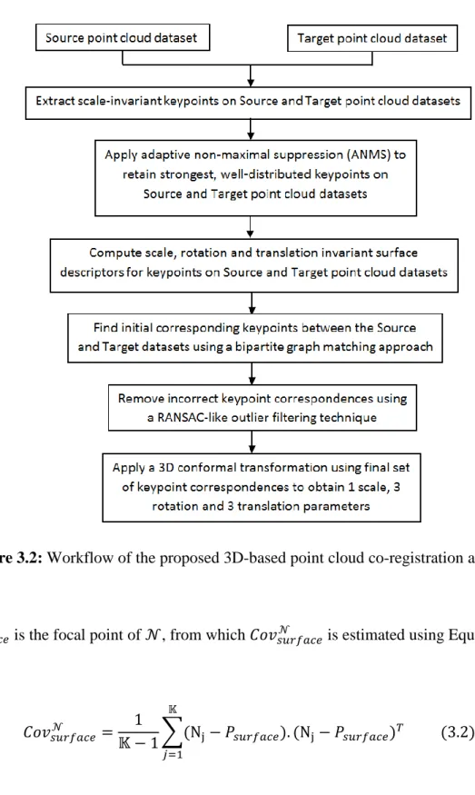
any proximate matching assumptions. The proposed 3D keypoint extraction and descriptor methods utilize various terrain characteristics such as curvature, slope and surface distances, specifically for the co-registration of urban and natural point cloud datasets. Figure 3.2 illustrates the proposed registration framework. In the following sections, each component of the framework is presented.
3.2 Extraction of 3D Surface Keypoints
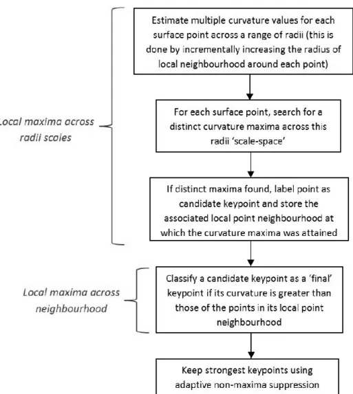
In this section, the aim is to establish discrete, 3D, stable and repeatable keypoints on the point cloud surface. Repeatable keypoints are those points that can be detected at the same location on both the source and target data, even in the presence of scale changes and rigid motion. To achieve this aim, a 3D detector has been developed which utilizes surface morphology, namely, the curvature of the point cloud surface, to find points of significance. The input datasets used in this 3D-based co-registration pipeline comprise of 3D point clouds with (x, y, z) coordinates. To classify a 3D surface query point cloud
𝑃𝑠𝑢𝑟𝑓𝑎𝑐𝑒 as a possible keypoint, the curvature at 𝑃𝑠𝑢𝑟𝑓𝑎𝑐𝑒 is computed. Given that
𝑃𝑠𝑢𝑟𝑓𝑎𝑐𝑒 is centered on a circular neighbourhood of surface point clouds 𝒩, the local surface curvature is estimated by utilizing the local covariance matrix 𝐶𝑜𝑣𝑠𝑢𝑟𝑓𝑎𝑐𝑒𝒩 . 𝒩 comprises of the 𝕂-nearest point neighboursaround 𝑃𝑠𝑢𝑟𝑓𝑎𝑐𝑒 (Equation 3.1).
𝒩 = [ N1 N2 . . . N𝕂] (3.1)
Figure 3.2: Workflow of the proposed 3D-based point cloud co-registration approach.
𝑃𝑠𝑢𝑟𝑓𝑎𝑐𝑒 is the focal point of 𝒩, from which 𝐶𝑜𝑣𝑠𝑢𝑟𝑓𝑎𝑐𝑒𝒩 is estimated using Equation 3.2.
𝐶𝑜𝑣𝑠𝑢𝑟𝑓𝑎𝑐𝑒𝒩 = 1
𝕂 − 1∑(Nj− 𝑃𝑠𝑢𝑟𝑓𝑎𝑐𝑒).
𝕂
𝑗=1
Eigen-decomposition of 𝐶𝑜𝑣𝑠𝑢𝑟𝑓𝑎𝑐𝑒𝒩 provides three eigenvalues 𝜆𝑢 and corresponding eigenvectors 𝑉𝑢 given in Equation 3.3. 𝑉𝑢 represents the three axes of the local, 3D orthogonal coordinate frame ℱ for 𝑃𝑠𝑢𝑟𝑓𝑎𝑐𝑒. 𝜆𝑢 represents the magnitude of the three ℱ axes and 𝑃𝑠𝑢𝑟𝑓𝑎𝑐𝑒 is ℱ’s origin. The magnitude of 𝜆𝑢<