Network Coding Aware Queue Management in
Multi-Rate Wireless Networks
Nicola De Coppi†, Jianxia Ning∗, George Papageorgiou∗, Michele Zorzi†, Srikanth V. Krishnamurthy∗ and Thomas La Porta‡
†University of Padova & CFR, Italy ∗University of California, Riverside, USA ‡Pennsylvania State University, USA
†{decoppin, zorzi}@dei.unipd.it, ∗{jning, gpapag, krish}@cs.ucr.edu, ‡ {tlp}@cse.psu.edu
Abstract—While network coding can potentially provide signif-icant throughput benefits by combining packets prior to forward-ing them, the achievable gains are directly related to the codforward-ing opportunities at a relay that performs encoding. If the relay does not have packets destined for distinct destinations, that can be encoded together, the network coding gains could be marginal. Towards increasing the opportunities for network coding, in this paper we propose a queue management scheme, that arbitrates the rate at which distinct transmitters send packets to a common relay which applies network coding. Our queue management approach prioritizes the channel access of nodes that do not have enough enqueued packets at the common relay, thereby essentially attempting to balance the number of packets from the distinct senders at the relay. We perform extensive simulations of our approach (built as a wrapper on top of the popular network coding approach COPE) in multi-rate scenarios. We find that our approach yields throughput gains of up to 57% compared to COPE due to enhanced opportunities towards encoding packets.
I. INTRODUCTION
Network coding has been proposed to increase the capacity of wireless networks towards the ever increasing demand for wireless capacity due to the emergence of high bandwidth applications. The fundamental idea in network coding is to reduce the number of wireless transmissions by encoding together different packets. In contrast with the traditionalstore
and forward paradigm, network coding uses a store, code
and forward approach. Network coding has been applied in
both multicast and unicast contexts. In particular, the COPE architecture [1] for network coding in wireless mesh networks has received a lot of attention; COPE has shown that it can improve the throughput of unicast traffic in dense networks with bursty flows. In addition, network coding aware rate adaptation algorithms [2] [3] have recently been proposed; these are built on top of the COPE architecture to further increase throughput.
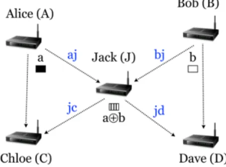
Scenario of Interest:First, let us revisit network coding in brief. Let us consider the five node topology as in Fig. 1. The five nodes typically occur in larger networks and thus, this topology is often analyzed for its simplicity. In this topology there are two flows, from Alice to Dave and from Bob to
Chloe.Jackis the relay node and is responsible for forwarding
packets. When COPE is used, Jack transmits an XOR of the packets (a ⊕ b) received from Alice (a) and Bob (b). Using network coding the number of transmissions is reduced from four to three. However, in this example, to decode the coded packet successfully, ChloeandDavehave to correctly overhear packets a and b, respectively. The radio channel
conditions between the sender and the overhearing node, and the transmission rates ofAliceandBob, affect the overhearing
atChloeandDave. IfChloecannot overhear the packet from
Alice, it will not be able to decode the XORed packet from
Jackand the native packet will have to be retransmitted.
Fig. 1. A topology of five nodes with network coding. Two flowsAlice→
DaveandBob→Chloego viaJackwho performs network coding. Loss in Coding Opportunities: When a relay node that performs network coding (Jack) has packets for different next hops (Chloe and Dave), it computes the probability that the receiver nodes can decode the coded packet. If the probability is greater that a certain threshold, it XORs native packets destined for these next hops and sends the coded packet on the wireless channel. However, if the relay does not have packets for the different next hop nodes (Chloe and Dave), it has to send each native packet as they are and thus, the coding opportunity is lost. To visualize the problem, assume thatJack
maintains virtual queues forChloe andDave. If there is
im-balancebetween these virtual queues, the likelihood that one
of these queues becomes empty increases and consequently
Jackloses coding opportunities.
Losing coding opportunities can be detrimental to through-put gains possible with network coding and should be avoided, especially in the presence of heavy traffic. Let us again consider our example withAlice,BobandJack. If CSMA/CA is the MAC protocol in use, each node in the same Carrier
Senserange has the same probability of accessing the channel
in the long term. Since the input traffic for Jackis twice its output rate, it starts accumulating packets in the queue. IfJack
uses network coding, it drains the queue faster. However, at each instance that Jackloses a coding opportunity, it reduces the rate at which its queue is drained and this contributes to an accumulation of packets in its queue.
Balancing the aforementioned virtual queues can avoid such losses of coding opportunities. One solution could be to use a perfect schedule wherein Alice and Bob send packets to
Jack’s queue at equal rates. Jackcan explicitly tellAliceand
Bob when to transmit. However, Jack may be unaware of whether or not Aliceand Bob have packets to transmit; thus a perfect schedule is difficult to implement. Moreover, today most systems use the popular IEEE 802.11 MAC standard. A second simple approach could be for Jack to delay the transmission of a packet until a coding opportunity is created (e.g., Alice’s packet is not forwarded unless there is also a packet fromBob). However, this can result in the filling up of
Jack’s queue and can also cause unnecessary delays; in fact, COPE is built on the underlying principle of never delaying packets.
Our contributions: Based on these considerations, in this paper we propose a queue management approach to increase the probability of coding packets (coding opportunities) in a multi-rate wireless network. Our proposed approach adaptively prioritizes channel access of the transmitters to a relay, based on the states of the virtual queues at the relay. Specifically, the probability of these nodes accessing the channel is adaptively varied by tuning the Contention Window (CW) size at the
MAC layer. Adjusting the CW size can be implemented via minor modifications to the IEEE 802.11 standard and has also been used in other contexts (e.g., in [4] and [5]). Based on how many packets are in the virtual queues and the quality of the links, the relay node (Jack) provides the sender nodes (Alice
andBob) with suggested values ofCWmin, towards balancing its virtual queues. The value of CWmin is inserted in the header of a COPE packet when such a packet is transmitted by Jack.
The paper is organized as follows. In Section II we present previous studies on network coding and queue management. In Section III we propose our queue management approach. In Section IV we evaluate the performance of our approach via extensive simulations. Section V concludes our work.
II. RELATEDWORK
In this section, we describe relevant related work. We first discuss related work on network coding and later that on queue management.
A. Related work on network coding
Most of the work on network coding in the literature is related to multicast traffic. Network Coding was introduced for the first time by Ahlswelde et al. [6], who showed that routers can achieve multicast capacity by mixing information in different messages. This work was followed by that of Li
et al. who showed that linear codes achieve the maximum
capacity bound [7]. They proposed linear network coding
where the output at a relay is obtained as a linear combination of its input flows. However, this approach needs centralized knowledge about the network topology. Koetter and Medard proposed random network codingwhere the linear codes are substituted with codes generated by a polynomial algorithm
[8]. Chou et al. proposed a distributed scheme for pratical network coding which does not need centralized knowledge of the network topology [9].
Katti et al. applied network coding to unicast traffic and integrate network coding into the current network stack [1]. They proposed COPE, a distributed scheme for network coding. With COPE each station is in promiscuous mode to overhear packets which are then stored for a short time
T and used for decoding. A relay needs to know which packets its neighbors have in order to be able to code. This information can be sent in periodic reception reports or can be estimated using a routing protocol based on the ETX/ETT metric. COPE by default uses the lowest rate available (i.e., 6 Mbps in IEEE 802.11g). It has been shown in [2] and [3] that network coding aware rate adaptation algorithms can further increase the capacity of wireless networks. None of these efforts however, examine the loss of coding opportunities due to a mismatch in the transmission rates of senders to a common relay. Note that in our work we consider this problem in a multi-rate setting.
B. Related work on queue management
Most of the queue management algorithms in the literature are proposed to improve congestion control with TCP (e.g., [10], [11]). In the context of network coding, queue models for both unicast [12] and multicast flows have been studied in [13], [14]. Seferogluet al.propose a queue management algorithm for TCP flows with COPE in [15]. They observe that a mismatch between flow rates can reduce coding opportunities. This mismatch is due to the fluctuation of wireless channel quality. They propose a change to the congestion control mechanisms of TCP to deal with this issue. In particular, when a node is congested, it chooses which packets to drop and the source reduces its packet generation rate. However, their solution does not consider that different flows may have different data rates. In contrast, our approach considers the use of multiple bit-rates in wireless networks; it is also independent of the transport protocol, and thus can be used with both UDP and TCP.
III. OURPROPOSEDQUEUEMANAGEMENTAPPROACH
As discussed, ensuring balanced throughput fromAliceand
Bob can increase Jack’s coding opportunities (Fig. 1). We propose to tune the CWs at the senders towards achieving this. We propose a queue management algorithm initiatied by
Jack towards estimating the proper CW sizes for Alice and
Bob.Jackthen feeds back this information to AliceandBob. First, let us look at how the queue is managed at the relay nodeJackin the COPE architecture. With COPE, each packet enqueued in the output queue at Jack is also enqueued in a
virtual queueto the packet’s next hop (ChloeorDave). When
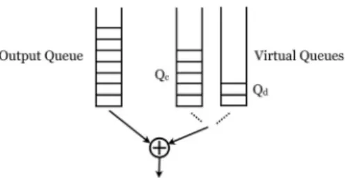
Jacksenses the channel to be idle, it dequeues the first packet in the output queue and searches the virtual queues to check whether there is a packet with a different next hop, that can be encoded with the dequeued packet (see Fig. 2). The use of virtual queues speeds up the search.
Fig. 2. Output queue and Virtual queues at the relay node for different next hop recipients.QcandQdare the sizes of the Virtual queues headed toChloe
and toDaverespectively.
Fig. 3. Block representation of our queue management algorithm.
Having unbalanced virtual queues increases the probability that some of these become empty and thus, cause Jack to miss out on coding opportunities. With our queue management algorithm we want to reduce the probability that a virtual queue becomes empty. We achieve this by appropriately pri-oritizing the channel access of either Aliceor Bob. Based on (i) information on the size of the virtual queues destined to
Chloe andDave(Qc, Qd in Fig. 2), and (ii) the packet error
rates (PERs) on the four links aj, bj, jc, jd, (see Fig. 1), our algorithm computes the appropriate CW sizes for Alice and
Bob, towards balancing their virtual queues at Jack. In other words, our algorithm takesQc,Qd,P ERaj,P ERbj,P ERjc and P ERjd as input and outputs the values of CWmina and
CWb
min, the contention window sizes for AliceandBob(see Fig. 3).1 Next, we describe the key design elements of our
algorithm, and then present the algorithmic details.
The effect of PER on the sizes of the virtual queues:The imbalance in the virtual queues maintained atJackis primarily because of mismatches in the packet error rates (PER) on the various links in the considered network. Specifically, we make the following observations:
• For the links Alice →Jack and Bob →Jack, when the medium access is fair as in CSMA/CA and P ERaj >
P ERbj,Alice has to transmit a packet more times than
Bob. Thus, atJackthe virtual queue that enqueues packets
from Alicewill have fewer packets than that fromBob.
• For the receiver links Jack→ ChloeandJack→ Dave, whenP ERjc> P ERjd,Jackaccumulates more packets headed to Chloe (due to a requirement for a higher number of retransmissions).
Tuning CWa
min and CWminb for balancing queues: By considering the entire path along which packets are delivered
(Alice → Dave andBob → Chloe), one can estimate which
virtual queue will tend to have fewer packets (atJack). Based on this, we propose to tune the congestion windows used for
1The algorithm does not use explicitly any information about the quality
of the overhearing links, but we simply assume that this quality is sufficient not to make network coding infeasible.
MAC access byAliceandBob, towards balancing the virtual queues.
We consider the fraction of P ERreceiver
P ERsender .Based on this frac-tion, we definesenderminandsendermaxto be the following:
sendermin|min !P ER jd P ERaj, P ERjc P ERbj " (1) sendermax|max ! P ERjd P ERaj, P ERjc P ERbj " , (2)
where, the notation | refers to the sender (Alice or Bob) with the minimum (or maximum) value of the aforementioned fraction. If the virtual queue gets drained faster than the rate at which the packets come into the queue, the queue tends to empty faster. In contrast, if packets arrive to the queue faster than they are drained, the queue tends to fill up. sendermin
is the sender (betweenAlice andBob) whose queue tends to fill up (the fraction is typically<1); sendermax refers to the sender whose virtual queue tends to empty out (the fraction is typically>1). Thus, our goal is to appropriately increase the probability of packet transmission of sendermin or decrease that ofsendermaxso as to balance the virtual queues atJack. Consider a link with a packet error rate P ERlink. Then, the average number of successful packet transmissions on this link is:
1 (1−P ERlink)
. (3)
The transmission probability (assuming a fixed contention windowW) is:
p= 2
(W+ 1). (4)
To increase the rate at which the sender with the higher queue imbalance sendermin sends packets to Jack, we de-crease its Contention Window to:
CWmini =K∗(CW
j
min+ 1)−1 (5)
whereiis thesendermin node andj is the other node.K is a coefficient that depends on the P ERs of the links on the two paths (defined below). Suppose that Alice is sendermin
and we want to increase her transmission probability while keeping the contention window of Bob (viz. CWb
min) fixed
at 31 (unchanged from default settings). We compute the contention window ofAliceto be:
CWmina =K(CWminb + 1)−1 (6) whereK= (1−P ERaj)(1−P ERjc)
(1−P ERbj)(1−P ERjd). Note here thatK≤1since Aissendermin, i.e., the contention window size is decreased. This decrease balances the delivery probability of the packets on the two paths Alice → Dave and Bob → Chloe and, in turn, balances the virtual queues atJack.
Alternatively, one can decrease the probability of transmis-sion ofBob by increasing his contention window. We fix the window of Alice to be CWa
min = 31; we compute CWminb
using (6) except that in lieu of K we use a new coefficient
K#=K−1 ≥1.
The above solution is used in our queue management al-gorithm. In particular, when the virtual queues become highly unbalanced, we reduce or increase the contention window. The details of the algorithm are presented later.
Communicating to the sender nodes the value of the congestion window to use : We insert the value of CWmin
in the COPE header by adding a new field. Thus, whenever
Jack sends a packet to Chloe or Dave, nodes Aliceand Bob
can overhear the packet by operating in promiscuous mode and extract the suggested minimum CW values from the header. The overhead for adding the field is negligible; only a few bits per node are needed.
Fig. 4. FIFO output queue divided in three segments.
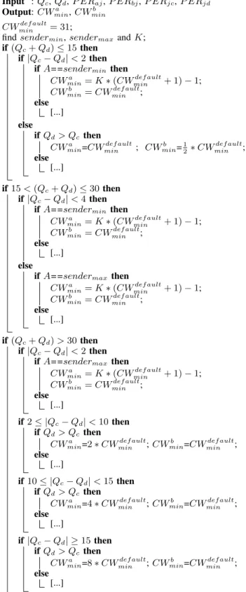
Details of the algorithm: Recall that our core objective is to ensure that the output queues at the relay node (Jack) have enough packets from both paths to prevent the loss of coding opportunities. Furthermore, the relay node should not have too many enqueued packets; if it does, packets may be dropped resulting in a degradation of the end-to-end throughput. Depend-to-ending on the queue (buffer) capacity, we propose to divide the output queue into three segments as shown in Fig. 4. The example values (15 and 30) are for a queue capacity of 50 packets.
• If the output queue size (Qc+Qd)≤15 and the value
|Qc−Qd|<2, we increase the transmission probability of the sendermin node as per (6). If the virtual queues become highly unbalanced (|Qc−Qd| ≥2) we divide by 2 the CWmin of the node with fewer packets.
• If the queue size is such that 15<(Qc+Qd)≤30and
|Qc−Qd| <4,we increase the transmission probability of thesenderminnode as per (6). Otherwise we decrease the transmission probability of the sendermax node.
• If the queue size is (Qc+Qd)>30, there is a risk that the queue becomes full and begins to drop packets. In this case, we reduce the transmission probability of the node with the higher number of packets: the higher the difference |Qc−Qd|, the higher theCWminof the node whose queue has more packets. We double the window size until the virtual queue size decreases to below30. In the third case, note that when we reduce the transmission probability of the sender node (AliceorBob) with the higher number of packets in the queue, Jackhas higher probability of accessing the channel and is able to drain his queue faster. The pseudocode of our queue management algorithm, ap-plied at Jack which is the relay node, is provided in Algo-rithm 1. The notation [...] under each “else” in the algorithm defines the same actions taken in the corresponding “if” part, in which the roles ofCWa
min andCWminb have been swapped
and K is substituted withK−1.
Input :Qc,Qd,P ERaj, P ERbj, P ERjc,P ERjd
Output:CWa
min,CWminb
CWmindef ault= 31;
findsendermin,sendermax andK;
if(Qc+Qd)≤15then
if|Qc−Qd|<2then
ifA==sendermin then
CWa
min=K∗(CWmindef ault+ 1)−1;
CWb
min=CWmindef ault;
else
[...]
else
ifQd> Qcthen
CWa
min=CWmindef ault; CWminb =12∗CW
def ault min ; else [...] if15<(Qc+Qd)≤30then if|Qc−Qd|<4then
ifA==sendermin then
CWa
min=K∗(CWmindef ault+ 1)−1;
CWminb =CWmindef ault;
else
[...]
else
ifA==sendermax then
CWmina =K∗(CWmindef ault+ 1)−1;
CWb
min=CWmindef ault;
else
[...]
if(Qc+Qd)>30then
if|Qc−Qd|<2then
ifA==sendermax then
CWmina =K∗(CWmindef ault+ 1)−1;
CWb
min=CWmindef ault;
else
[...]
if2≤ |Qc−Qd|<10then
ifQd> Qcthen
CWa
min=2∗CWmindef ault;CWminb =CWmindef ault;
else
[...]
if10≤ |Qc−Qd|<15then
ifQd> Qcthen
CWa
min=4∗CWmindef ault;CWminb =CWmindef ault;
else
[...]
if|Qc−Qd| ≥15then
ifQd> Qcthen
CWa
min=8∗CWmindef ault;CWminb =CWmindef ault;
else
[...]
Algorithm 1: Pseudo code of our queue management algo-rithm.
0 10 20 30 40 50 60 70 0 20 40 60 80 100 120 140 Simulations % Throughput Improvement with COPE+QUEUE MGMT with COPE
average with COPE+QUEUE MGMT average with COPE
Fig. 5. Throughput gain over a typical IEEE 802.11 system in two cases: with COPE and with COPE + QUEUE MGMT.
IV. SIMULATIONRESULTS
In this section, we use NS 2.34 [16] simulations to evaluate the proposed queue management algorithm. Since multi-rate transmissions are not supported by NS 2 by default, we used an external library [17]. For the implementation of COPE we began with the Google project [18] and retained the basic structure implemented in the project. We made some modi-fications and, in particular, changed the coding and decoding processes to exactly conform to the corresponding operations of COPE.
We use IEEE 802.11g, which allows transmissions at 6, 9, 12, 18, 24, 36, 48 and 54 Mbps. Since we deal with static networks, stable Signal-to-Noise Ratios (SNRs) are observed at nodes. The SNR is measured from packets sent on the wireless link; it depends on the distance between two nodes and on the noise power. For the same SNR, transmitting at a lower rate will result in a lower error rate. We use an SNR-based rate adaptation algorithm where each node chooses the highest rate so as to allow all of its neighbors to overhear packets withP ER≤0.2.
We consider the five node topology in Fig. 1. Two saturated UDP traffic flows are initiated from Alice toDave and from
Bob to Chloe. Each node uses a transmission power of 20
dBm. The 2.4 GHz frequency band is used. The free-space path loss channel model is assumed. The packet size is set to 1500 Bytes. The positions of the nodes are generated randomly and the noise power is randomly chosen from the setN={10−10,2 ×10−10,3 ×10−10,4 ×10−10,5 ×10−10 }; these values are chosen to be close to the default settings in NS 2. The combination of node positions and noise powers allows us to vary the PER on each link. We consider 73 different combinations. The simulations last for 100 seconds and the results shown are the average over three simulations;
0 20 40 60 80 0 20 40 60 80 100 Simulations
% Coded Packets at the Relay Node J
% Coded Packets Mean (a) 0 20 40 60 80 0 20 40 60 80 100 Simulations
% Coded Packets at the Relay Node J
% Coded Packets Mean
(b)
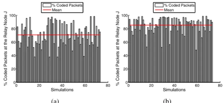
Fig. 6. Fraction of coded packets over total number of sent packets at the relay node with (a) COPE and (b) COPE + QUEUE MGMT . The average increases from 70% to 85%. 0 20 40 60 80 0 10 20 30 40 50 Simulations
Output Queue at the Relay Node J
Packets headed to C Packets headed to D (a) 0 20 40 60 80 0 10 20 30 40 50 Simulations
Output Queue at the Relay Node J
Packets headed to C Packets headed to D
(b)
Fig. 7. Size of the output queue with packets headed toC andD with (a) COPE and (b) COPE + QUEUE MGMT. In the second case the virtual queues are more balanced.
we check the results from the three runs and verify that we have sufficient statistical confidence.
We compare the throughput of the system obtained without COPE, with COPE and with COPE + QUEUE MGMT. Fig. 5 shows the throughput improvements of the system in the 73 different topologies (based on PERs) with COPE and with COPE + QUEUE MGMT with respect to the throughput without COPE. We notice that our algorithm enhances the performance of COPE when COPE’s gain is low. On average our algorithm increases COPE’s performance by 7.5%, with a maximum improvement of 57%. Furthermore, the fraction of encoded packets at the relay node increases from 70% with COPE to 85% with COPE + QUEUE MGMT (Figs. 6 (a) and (b)). Lastly, the average difference between the virtual queues is 10 packets with COPE and 2.7 packets with COPE + QUEUE MGMT (Figs. 7 (a) and (b)). This shows that our algorithm is able to balance the virtual queues at the relay node and thereby improve coding opportunities.
A. The Best Improvement Case
First we consider the case where our algorithm provides a system gain of 57%. This case is shown in Fig. 8. The noise power is fixed toN = 4×10⁻¹⁰. We observe that the
receiver links have different values of PER (P ERjc = 0.18 andP ERjd = 0.009). Packets headed to Chloe, denoted by
C, will tend to accumulate at the relay node queue (as shown in Fig. 10 (a)).
Fig. 8. SNR (in dB), data rate and PER for each link in the case where we obtain the best throughput improvement with COPE + QUEUE MGMT.
2 4 6 8 10 12 14 1.5 2 2.5 3 3.5 4 4.5 5 5.5 Offered load [Mbps] Network Throughput [Mbps] Without COPE
With COPE With COPE+QUEUE MGMT (a) 2 4 6 8 10 12 14 0 10 20 30 40 50 60 70 80 90 100 Offered load [Mbps] Percentage Coded With COPE With COPE+QUEUE MGMT (b)
Fig. 9. (a) COPE+QUEUE MGMT provides 57% increase in UDP through-put in the presence of saturated traffic. (b) Percentage of packets encoded at the relay nodeJack.
2 4 6 8 10 12 14 0 10 20 30 40 50 Offered load [Mbps]
Output Queue at the Relay Node J
Packets headed to C Packets headed to D (a) 2 4 6 8 10 12 14 0 10 20 30 40 50 Offered load [Mbps]
Output Queue at the Relay Node J
Packets headed to C Packets headed to D
(b)
Fig. 10. Size of the output queue with packets headed toChloeandDave(a) with COPE and (b) COPE + QUEUE MGMT. In case (b) the output queue size is reduced and the virtual queues are more balanced.
We gradually increase the offered load in the considered scenario. We see in Fig. 9(a) that the systems have the same throughput as long as the offered traffic is low. At high traffic loads, the performance degrades. However, COPE with our algorithm is able to better cope with the performance degradation by adaptively tuning the transmission probabilities via contention window adjustments. We point out that the fraction of encoded packets is higher with our algorithm (see Fig. 9 (b)). If we look at the output queue at the relay node with only COPE (Fig. 10(a)), we see that the relay node does not accumulate packets in its output queue if the offered load is less than 5 Mbps. After that, the average queue size quickly becomes 45 packets. This means that packets have a high probability of being dropped because the output queue often reaches the maximum size of 50 packets. Moreover, the virtual queues are highly unbalanced. Our algorithm (Fig. 10(b)) reduces the size of the output queue to 30 packets and balances the number of packets headed to different next hop nodes,
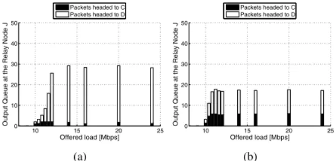
Fig. 11. SNR (in dB), PHY rate and PER for each link in a case where we obtain about a 7% throughput improvement with COPE+QUEUE MGMT.
8 10 12 14 16 18 20 22 24 5.5 6 6.5 7 7.5 8 8.5 9 9.5 10 10.5 Offered load [Mbps] Network Throughput [Mbps] Without COPE With COPE With COPE+QUEUE MGMT (a) 8 10 12 14 16 18 20 22 24 0 10 20 30 40 50 60 70 80 90 Offered load [Mbps] Percentage Coded With COPE With COPE+QUEUE MGMT (b)
Fig. 12. (a) COPE+QUEUE MGMT provides 7% increase in UDP through-put in the presence of saturated traffic. (b) Percentage of packets encoded at the relay nodeJack.
10 15 20 25 0 10 20 30 40 50 Offered load [Mbps]
Output Queue at the Relay Node J
Packets headed to C Packets headed to D (a) 10 15 20 25 0 10 20 30 40 50 Offered load [Mbps]
Output Queue at the Relay Node J
Packets headed to C Packets headed to D
(b)
Fig. 13. Size of the output queue with packets headed toChloeandDave
with COPE (a) and COPE+QUEUE MGMT (b). In the second case the output queue is reduced and the virtual queu es are more balanced.
thereby increasing coding opportunities at the relay.
B. The Average Improvement Case
In this case, COPE + QUEUE MGMT provides throughput gains of about 7% over COPE as seen in Fig. 12(a). Here, we see that there is a difference in the PERs on sender links (P ERbj = 0.144 and P ERaj = 0.012 as in Fig. 11). In addition, the receiver links have low values of PERs. As seen from Fig. 13(a), without the queue management scheme the relay node accumulates packets headed to Dave, denoted by
D. This is because of the fact that the relay node receives more packets from Alice(denoted byA), sinceP ERaj < P ERbj, and thus is able to encode only 60% of the packets, losing coding opportunities. Again, our algorithm reduces the size of the output queue while making the virtual queues more balanced (Fig. 13(b)).
V. CONCLUSIONS
In this paper we proposed a queue management algorithm on top of the COPE architecture to increase the coding opportunities and network throughput. Our algorithm balances the virtual queues headed to different next hop recipients at a relay node, by adaptively tuning the contention windows of the sender nodes. We simulated our scheme considering a five node topology and the IEEE 802.11g standard. We compared the system without COPE, with COPE and with COPE + QUEUE MGMT. Our algorithm achieves a best case throughput gain of 57% over COPE, with an average gain of 7.5%. As a future work we plan to investigate the scalability of our approach by implementing it and studying the behavior of the relay nodes in a larger network.
ACKNOWLEDGMENTS
This work was partially supported by the US Army Re-search Office under the Multi-University ReRe-search Initiative (MURI) grant W911NF-07-1-0318, by the NSF NeTS grant 1017012 and by the European Commission under the FP7 EU project SAPHYRE, grant agreement no. 248001.
REFERENCES
[1] S. Katti, H. Rahul, W. Hu, D. Katabi, M. Medard, and J. Crowcroft, “XORs in the air: Practical wireless network coding,”IEEE/ACM Trans. Netw., vol. 16, no. 3, pp. 497–510, Jun. 2008.
[2] T.-S. Kim, S. Vural, I. Broustis, D. Syrivelis, S. Krishnamurthy, and T. La Porta, “A framework for joint network coding and transmission rate control in wireless networks,” inProceedings of INFOCOM, 2010, Mar. 2010.
[3] R. Kumar, S. Tati, F. de Mello, S. Krishnamurthy, and T. La Porta, “Network coding aware rate selection in multi-rate IEEE 802.11,” in
Proceedings of the18th IEEE International Conference on Network
Protocols (ICNP), 2010, Oct. 2010, pp. 92–102.
[4] A. Nafaa, A. Ksentini, A. Mehaoua, B. lshibashi, Y. Iraqi, and R. Boutaba, “Sliding contention window (SCW): towards backoff range-based service differentiation over IEEE 802.11 wireless LAN networks,”
IEEE Netw., vol. 19, no. 4, pp. 45–51, Jul. 2005.
[5] L. Gannoune and S. Robert, “Dynamic tuning of the contention win-dow minimum (CWmin) for enhanced service differentiation in IEEE 802.11 wireless ad-hoc networks,” inProceedings of the 15th IEEE
International Symposium on Personal, Indoor and Mobile Radio Com-munications, PIMRC 2004, vol. 1, Sep. 2004, pp. 311–317.
[6] R. Ahlswede, N. Cai, S.-Y. Li, and R. Yeung, “Network information flow,”IEEE Trans. Inf. Theory, vol. 46, no. 4, pp. 1204–1216, Jul. 2000. [7] S.-Y. Li, R. Yeung, and N. Cai, “Linear network coding,”IEEE Trans.
Inf. Theory, vol. 49, no. 2, pp. 371–381, Feb. 2003.
[8] R. Koetter and M. Medard, “An algebraic approach to network coding,”
IEEE/ACM Trans. Netw., vol. 11, no. 5, pp. 782–795, Oct. 2003. [9] P. A. Chou, Y. Wu, and K. Jain, “Practical network coding,” in
Proceedings of Allerton Conference on Communication, Control, and Computing, 2003.
[10] S. Athuraliya, S. Low, V. Li, and Q. Yin, “REM: Active Queue Management,”IEEE Netw., vol. 15, no. 3, pp. 48–53, May 2001. [11] F. W-C., K. Shin, D. Kandlur, and D. Saha, “The BLUE active queue
management algorithms,”IEEE/ACM Trans. Netw., vol. 10, no. 4, pp. 513–528, Aug. 2002.
[12] S. E. Tajbakhsh, M. Orang, M. H. Sohi, and A. Movaghar, “A queuing model of opportunistic network coding in wireless medium,” in Interna-tional Conference on the Latest Advances in Networks (ICLAN), 2008. [13] B. Shrader and A. Ephremides, “A queueing model for random linear coding,” inIn the proceedings of the IEEE Military Communications Conference, MILCOM 2007, Oct. 2007.
[14] M. Iraji, M. Amerimehr, and F. Ashtiani, “A queueing model for wireless tandem network coding,” inIn the proceedings of the IEEE Wireless Communications and Networking Conferences. WCNC 2009, Apr. 2009.
[15] H. Seferoglu and A. Markopoulou, “Network coding-aware queue man-agement for unicast flows over coded wireless networks,” inProceedings of the IEEE International Symposium on Network Coding (NetCod), 2010, Jun. 2010, pp. 1–6.
[16] The Network Simulator, “ns-2,” http://nsnam.isi.edu/nsnam/index.php/ Main Page.
[17] dei80211mr, “An improved 802.11 implementation for ns2 with en-hanced interference model.” http://www.dei.unipd.it/wdyn/?IDsezione= 5090.
[18] COPE on ns2, “Google project by Uppsala University,” http://code. google.com/p/uu-cope/.