1.Introduction
As environmental issues become more prominent, energy generated by wind has gradually increased year by year. Application fields of wind energy have been gradually ex-tended to the industrial areas from agricultural irrigation, navigation and grinding. However, due to the randomness of wind power, WECS (wind energy conversion systems) may implement either VSWT (variable speed wind tur-bines) or VSVPWT (variable speed variable pitch speed wind turbines) [1-6]. When the wind speed is below the rated value, wind energy conversion efficiency is used for improving the wind energy conversion efficiency. The commonly control strategy for capturing most wind en-ergy is maximum power point tracking (MPPT) [7], and corresponding control methods include PI [8] control, LPV [9] control, neural network control [10,11], etc. However, the above control methods for energy conver-sion systems have an undesirable effects, as the existence of many nonlinear and uncertain facts caused by the wind.As the PID control of the WECS based on the fuzzy logic ruler hasgood adaptive capacity, the effect applied to the VSWT WECS is ideal [12]. Giuseppe and Pietro [13] developed a method for predicting working state of
wind turbines with neural network control. Sargolzaei and Kianifar [14] presented a control strategy for improving the power quality with neural network control. Yurdusev et al. [15] developed a method for tracking optimal tip speed ratio with the neural network. Compensation con-trol of neural network is proposed to suppress interference of wind power systems [16]. RBF neural network is ap-plied in the variable-pitch control system [17]. When the wind speed is above the rated value, LPV compensator for VSWT WECS is designed to regulate the high fre-quency output of wind generator torque and blade angle pitch, combining neural network control with PID control, a new type of PID neural network intelligent controller for VSVPWT WECS is designed for dynamic compensate steady-state output. The training algorithms used are gra-dient descent algorithm with momentum factor, which presents the on-line version of auto-tuning algorithm for PID control parameter. A hardware platform for multi-variable compensation control of the VSVPWT WECSis built up based on Dspace. The results confirm the superi-ority of the proposed control (multi-variable in this paper) scheme to the conventional ones(traditional multi-vari-able).Fathabadi [18] proposed a novel fast and highly ac-curate universal maximum power point (MPP) tracker for hybrid fuel cell/photovoltaic/wind power generation sys-tems. The tracker called “universal tracker” because it used a unified algorithm and controller to concurrently track the MPPs of the photovoltaic (PV), fuel cell (FC) and wind energy conversion subsystems of a hybrid FC/PV/wind power system. Soufi et al. [19] proposed a
Intelligent Control for the Variable-Speed Variable-Pitch
Wind Energy System
M. Heidari (C.A.)
Abstract:In this paper, a new type of multi-variable compensation control method for the wind energy
con-version systems (WECS) is presented. Based on wind energy concon-version systems, combining artificial neural network (ANN) control and PID, a new type of PID NN intelligent controller for steady state torque of the wind generator is designed, by which the steady state torque output is regulated to track the optimal curve of wind power factor and the blade pitch angle is regulated to keep the stable power output. Also, the LPV model of the WECS, LPV compensator for the wind generator is designed to effectively compensate output of the wind generator torque and the blade pitch angle. Finally, simulation models of the control system based on a realistic model of a 8kw wind turbines are built up based on the Dspace platform. The results show that the proposed method can reduce interferences caused by disturbed parameters of the WECS, me-chanical shocks of the wind generator speed are reduced while capturing the largest wind energyfluctuation range of wind generator power output is reduced, and the working efficiency of the variable pitch servo sys-tem is improved.
Keywords: ANN, Dspace, PID NN, Wind Energy Conversion Systems.
Iranian Journal of Electrical & Electronic Engineering, 2017. Paper received 8October 2016 and accepted 19 July 2017.
*The Author is with the Department of Mechanical Engineering, Aligu-darz Branch, Islamic Azad University, AliguAligu-darz, Iran.
E-mail: [email protected] Corresponding Author: M. Heidari.
particle swarm optimization based sliding mode control of squirrel cage induction generator of a variable speed wind energy conversion system. The proposed method had good transient performance and fast convergence. Hong et al. [20] presented a artificial neural network for optimal control for variable-speed wind generation sys-tems.
The rest of this paper is organized as follows. Section 1 discusses the constant power control problem and the modeling of the WECS from the multi-variable control point of view. Section 2 depicts an overview of the pro-posed control structure, presents a new LPV dynamic compensation control method for the variable-speed vari-able-pitch WECS. Section 3 presents a new PID neural network control structure, explain the training algorithm of the multi-variable controller. Section 4 presents the ex-perimental results with the proposed control method based on a 8000 watt wind turbine. Section 5 concludes this work and represents one of the main contributions in this paper.
2. LPV Modeling of Variable WECS
The aerodynamic model of a wind wheel is computed from Eq. (1) [7, 15].
where is C=0.5πρR3, Г(t), ρand Rare the torque of the rotor,the air density and wind wheel radius respectively.
Г(t) = Cv(t)2C
Г(λ, β) (1)
The parameter CГ (λ, β) is the torque coefficient thatde-pends on the blade pitch angle β and the tip-speed ratio λ determined from Eq. (2):
CГ(λ, β) = Cp(λ, β)/λ (2)
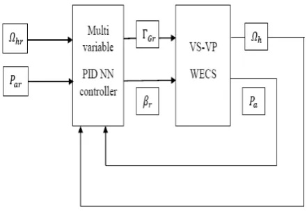
where Cp(λ, β)is the power coefficient, and the tip-speed ratio is λ=ΩlR/ѵ. Hereafter, the augmented system will be analyzed (see Figure 1 for a block diagram of the VSVPWT WECS), wind energy captured by the rotor of a wind wheel is computed from Eq. (3),
Pwt(t)=C/R ѵ(t)3C
p(λ, β) (3)
The nonlinear wind turbine is linearized around the steady-state operating point so as to obtain linear model of VSVPWT WECS [22]. Defining the error ∆x=x- , and the normalized errors . As the uncertainty of wind, we take the wind speed as stochastic processes of non-statistics, so it includes two part:
ѵ=ѵ+∆ѵ (4)
where, ѵ is low-frequency wind speed, ∆ѵ is high-fre-quency wind speed:
(5)
where, ξ is Gaussian white noise, Twis filter time con-stant, and , Lt is turbulence length of the wind speed. Linear parameter-varying (LPV) model for VSWT WECS can be expressed as [6, 18]:
(6)
where, state vector x, input vector ,
. Where, , , ,
is normalized wind wheel torque, is normalized generator torque, is normalized wind speed.
Parame-ters , B(Θ) and A(Θ) can be
ex-pressed as:
(7)
(8)
In Eq. (8), γ depends on the operating points of the
WECS. it defines as , and
.
JTis mechanical time constant of transmission system and define as follows:
ݔҧ
οݔ തതതത ൌ οݔ ݔҧൗ
ο˶ ൌ െ ͳ
ܶ௪ο˶
ͳ ܶ௪ߦ
ܶ௪ൌܮ௧ൗ˶ത
൜ݔሺݐሻ ൌ ܣሺܳሻݔ ܤሺܳሻݑ ܮሺܳሻݔ
ݖሺݐሻ ൌ ܥݔ ܦݑ
ݑሺݐሻ ൌ ሾοʒതതതതത οߚீ തതതതതതതሿ் , ߆ ൌ ߛሺ Where, οݒതതതത ൌ ൗݒҧ, οߗതതതതത ൌ οߗ Ȁ ߗത, οʒതതതതതത ൌ οʒ௪௧ ௪௧Ȁʒത
௪௧, ܦܩതതതതത௪ , ܦܩതതതതതതீ ܦݒ
തതതത
ܮሺ߆ሻ ൌ ሾͲ Ͳ ሺʹ െ ߛሻȀܶ௪ሿ்
ߛ ൌఒഥ ൫ఒഥǡఉഥ൯ ൫ఒഥǡఉഥ൯െ ͳ ܤሺ߆ሻ ൌ
ۏ ێ ێ ێ
ۍെͳȀܬͲ ் ͳȀܶͲ
ఉ
െߛȀܬ் ߦ ܶ ఉ
൘
ے ۑ ۑ ۑ ې
ܣሺ߆ሻ ൌ ൦
Ͳ Ͳ ͳȀܬ்
Ͳ െͳȀܶఉ Ͳ
ߛȀܶ௪ ்క
ೢെ
క ்ഁ
ߛ ܬ்
ൗ െ ͳ ܶൗ ௪ ൪
ܥሖ ൫ߣҧǡ ߚҧ൯ ൌ
ߣҧ ൌܴߗ
ݒҧ ൗ.
݀ܥሺߣҧǡ ߚҧሻȀ݀ߣȁఒୀఒഥǡఉୀఉഥ
ܬ்ൌ
ܬߗത
ʒത௪௧
ൌܬߗത ʒത௪௧
Fig. 1.Block diagram of the VSVPWT WECS
Affine coefficient matrix in the LPV model depending on the parameter vector Θ,which can be expressed as:
(9)
3. Designing of Multi-Variable Controller Based on the NN PID
3.1 MultivariableControl Strategy PID algorithm can be expressed as following:
(10)
u(k)is output of PID controller. To achieve better per-formance, a nonlinear multi-variable controller for the VSVPWT WECS have been proposed in [2]. Multi-vari-able controller includes two layers, the first layer is gen-erator torque controller, which is to regulate the output torque; the second layer is blade pitch angle controller, which is used to make the controller less complex and as the rotor speed regulation objective is partly guaranteed by the pitch controller. When the wind speed is above rated value, classical multi-variable control structure of the VSVPWT WECS is the following (Figure 2), two PID controllers are used as equations (11) and (12), [6, 21]:
(11)
(12)
Where , which is the generator speed tracking error, and , which is the generator output power tracking error, kp1and kp2are the proportional co-efficient, ki1and ki2are the integral coefficient, kd1and kd2are the differential coefficient.
However, the classical method depends on the linear op-erating point of the WECS, when the system is opop-erating far from the steady operating point, the rotor speed and power unfortunately presents large variations. The con-trollers (see Eq.(10)) are unable to obtain control rules with the input variable sum-of-error , that is inte-gral error, because the steady state value of inteinte-gral n error is unknown for VSVPWT WECS control systems. The proposed method (see Figure 3 for PID NN multi-variable control structure of the VSVPWT WECS), the PID neural
network can. This controller completes the online tuning of proportion, integral and differential parameters, and the network training algorithm by employing momentum fac-tor will not be easy to fall into a local minimum value.
3. 2. PID Neural Network Controller
In order to assist the torque controller to regulate the wind turbine electric power output, while avoiding significant loads and maintaining the rotor speed within acceptable limits, a proportional pitch controller is added upon the rotor speed tracking error:
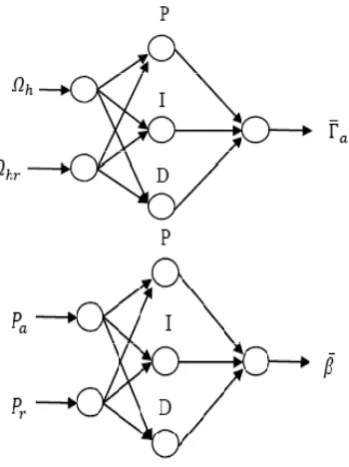
As is shown in Figure 4,there are two same 2-3-1 structure PID neural network controllerfor the multi-variable con-troller. Here we just give the torque controller [24, 25]: Two inputs of neural network are and , where, is
ቐ
ܣሺ߆ሻ ൌ ܣ ߆ܣଵ
ܤሺ߆ሻ ൌ ܤ ߆ܤଵ
ܮሺ߆ሻ ൌ ܮ ߆ܮଵ
ݑሺ݇ሻ ൌ ܭ݁ሺ݇ሻ ܭூ ݁ሺ݆ሻ ܭሾ݁ሺ݇ሻ െ ݁ሺ݇ െ ͳሻሿ
ୀ
ʒ ൌ ݁ఆሺ݇ଵ
݇ଵ
ݏ ݇ௗଵݏሻ
ߚൌ ݁ሺ݇ଶ
݇ଶ
ݏ ݇ௗଶݏሻ
݁ఆൌ ߗെ ߗ ݁ൌ ܲെ ܲ
σ ݁ሺ݆ሻ ୀ
ݔଵଵ ݔଶଵ
ݔଵଵ
Fig. 2.Classical multi-variable control structure of the
VSVPWT WECS
Fig. 3.PID NN multi-variable control structure of the
VSVPWT WECS
the speed reference value of wind turbines. is the actual rotational speed of wind turbines. The output of the input layer is , j=1, 2. The state function of neurons is . Hidden layer includes three neurons, proportional element, integral element, differen-tial element. The sum of input weight which in hidden layer neurons is , i=1, 2, 3, is the input weights of thei-th neurons which in the hidden layer. The state of proportional element is:
(13)
The state of integral element is:
(14)
The state of differential element is:
(15)
Output layerincludes one neuron. The sum of neurons input weight is , is the input weights of the l-th neurons which in the output layer, and l=1. The output of the output layer is ). The state func-tion of neurons is . The output functions of input layer and hidden layer are f 1and f 2, which are Tan-sig function. The output function of output layer is f 3,
which is purelinand wavelet function. The initial weights from input layer to hidden layer are , . The initial weights from hidden layer to output layer arethe output ratio of PID controller ,integration kI, differentia-tion kD.kpis proportional coefficient, kIis integral coef-ficient, kDis differential coefficient.The network training target can be expressed as:
(16)
Where, yopis actual output of the neural network, ytpis expected output of the neural network, m is sample size. PID neural network weight is to train by the gradient de-scent algorithm with momentum factor, the final training steps can be express as equations (17) and (18):
(17)
where, δ ́(k)=2[ytp-yop], equation (17) is weight correction from hidden layer to output layer.
(18)
where, equation (18) is
weight correction from input layer to hidden layer.
3. 3. LPV Gain Scheduling Control
Full state feedback controllers is expressed as equation (19)[21]:
(19)
The closed-loop system can be expressed as:
(20)
where, .
where, .
Gain matrix of parameter state feedback controller given by matrix inequality can be expressed as follows [23, 26]:
(21)
where, V and R(Θ) are symmetric positive definite ma-trix.
The Control structure of the variable-speed WECS with ݊݁ݐଶൌ σଶୀଵݕଵǤ ݓଶ ݓଶ
ݕଷൌ ݂ଷሺ݊݁ݐ ଷ
߲ܧ ߲ݓଶ
ൌ െͳ
݉ ߜሺ݇ሻݕଶሺ݇ሻ
ୀଵ
ݔൌ ܣҧሺ߆ሻݔ ܮሺ߆ሻߦ
ݖ ൌ ܥሺ߆ሻݔ
ܭሺ߆ሻ ൌ ܴሺ߆ሻܸିଵ
ݑଵଶሺ݇ሻ ൌ ݊݁ݐଵଶ
ݑଶଶሺ݇ሻ ൌ ݑଶଶሺ݇ െ ͳሻ ݊݁ݐଶଶ
ݑଷଶሺ݇ሻ ൌ ݊݁ݐଷଶሺ݇ሻ െ ݊݁ݐଷଶሺ݇ െ ͳሻ
ܧ௧ሺሻ ൌ
ͳ
ʹሾݕ௧െ ݕሿ
ଶ
ୀଵ
߲ܧ ߲ݓଷ
ൌ െͳ
݉ ߜሖሺ݇ሻݕ
ଶሺ݇ሻ
ୀଵ
ߜሺ݇ሻ ൌ ߜሖሺ݇ሻݓଶݏ݃݊ ௬మሺሻି௬మሺିଵሻ ௧మሺሻି௧మሺିଵሻ
ݑ ൌ ܭሺ߆ሻݔ
ܣҧሺ߆ሻ ൌ ܣሺ߆ሻ ܤሺ߆ሻܭሺ߆ሻǡ ܥҧ ൌ ܥ ܦܭሺ߆ሻ.
ͳ Ͳ Ͳ ͳ Ͳ
ܥ ൌ ͳ Ͳ Ͳ ͳ Ͳ Ͳ Ͳ Ͳ Ͳ
൩, ܦ ൌ ͳ Ͳ Ͳ Ͳ Ͳ Ͳ ൩
i f f db
ݕଵൌ݂ଵ൫݊݁ݐଵ൯ǡ ݑଵሺ݇ሻ ൌ ൫݊݁ݐଵ൯.
݊݁ݐଷൌ σ ݕ ଶ ଷ
ୀଵ ݓଷ
ݑଷሺ݇ሻ ൌ ሺ݊݁ݐ ଷሻ
ݓଶൌ ͳ,ݓଶൌ െͳ
ߗ
ݔଶଵ ߗ
Fig. 4.PID NN controller
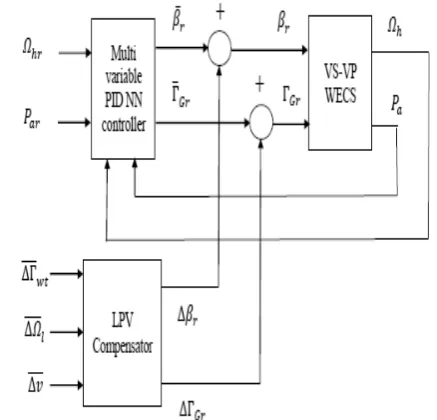
torque compensator is shown in Figure 5, As given in equations (22) and (23), where is the output of the torque controller, is the output of the blade pitch angle controller. Both the two controllers and the LPV compen-sator which outputs are ∆βrand ∆ГGrregulate the output power.
(22)
(23)
3. 4.SimulationResearch
The simulation model is set up so as to verify the control
ߚൌ ߚҧ οߚ
ʒீൌ ʒതீ οʒீ
ߚҧ
ʒതீ
Fig. 5.Control structure of variable-speed WECS with torque
compensator
i
(b)Goweroutput
0 20 40 60 80 100
1000 2000 3000 4000 5000 6000 7000 8000 9000
3 U R S R V H G 0 H W K R G
O
u
tp
u
t P
o
w
e
r
(W
)
Time(s)
& O D V V L F D O 0 H W K R G
60
(a)Windspeed
0 20 40 60 80 100
6 8 10 12 14 16 18 20
W
ind S
p
eed(
m
/s)
Time(s)
(c)Generatorspeed
0 20 40 60 80 100
0 10 20 30 40 50 60
3 U R S R V H G 0 H W K R G
Gener
a
tor
Speed
(r
ad/
s)
Time(s)
& O D V V L F D O 0 H W K R G
(d)Generatortorque
0 20 40 60 80 100
180 200 220
3 U R S R V H G 0 H W K R G
G
en
er
at
or
T
o
rque
(N.
M
)
Time(s)
& O D V V L F D O 0 H W K R G
Fig. 6.Blade pitch angle controller output
effect. There are two cases, the one is to test the blade pitch angle controller effect of PID neural network (see blade pitch angle controller output in Figure 6). It can be seen from Figure 6(b) to Figure 6(d), when changes of wind speed are immediate, system output has less distur-bances with the PID neural network controller than the PID controller.
The second is to test the torque controller effect of PID neural network (see torque controller output in Figure 7). As is shown in the Figures 7(b) and 7(c), wind power out-put can track the maximum power coefficient, and distur-bances with the PID neural network controller are less than the PID controller, so this method can keep the stable output of the VSVPWT WECS.
4. Experiment Results and Analysis
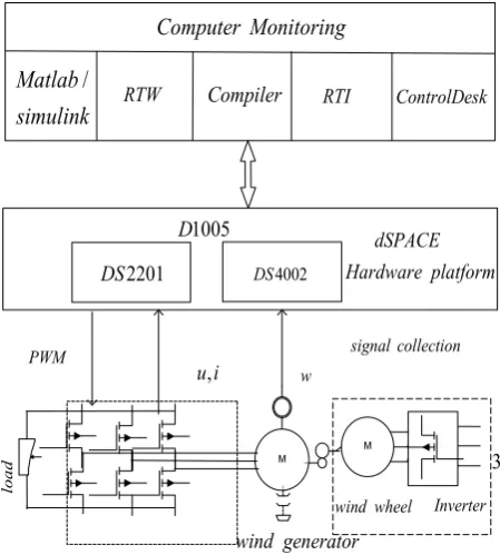
The Dspace experiment platform is shown in Figure 8, in-cluding Matlab/Simulink model, RTW model, Compiler model, RTI model, Control Desk model. Downloading the model compiled to processor through the establishment of Matlab/simulink model, the platform includes electric motor and wind generator [23]. Corresponding parameters of the VSVPWT WECS including: wind generator power is 8000 watt, gear ratio is 6.25, transmission efficiency of wind turbine is 0.95, time constant of filter is 10second, air density is 1.25 kg/m3, rated wind speed is 12.5 m/s. Wind generator speed output reference is 30 rad/s, wind generator torque output reference is 200 N.M.
Dspace experiment platform is set up so as to verify the control effect of the proposed Multi-variable controller. (a)Windspeed
0 20 40 60 80 100
2 4 6 8 10
W
ind S
peed
(m
/s
)
Time(s)
Computer Monitoring
dSPACE
Hardware platform
l
oa
d
signalcollection
wind wheel Inverter
wind generator
PWM
,
ui w
2201
DS DS4002
1005
D
/
Matlab
simulink RTW Compiler RTI ControlDesk
3
(b)Tipspeedratio
0 20 40 60 80 100
0 2 4 6 8 10 12
3 U R S R V H G 0 H W K R G
T
ip
Speed
R
at
io
Time(s)
& O D V V L F D O 0 H W K R G
(c) Power coefficient
0 20 40 60 80 100
0.0
0.2
0.4
0.6
0.8
3 U R S R V H G 0 H W K R G
Pow
e
r
C
oe
ff
i
c
ie
n
t
Time(s)
& O D V V L F D O 0 H W K R G
Fig. 7.Torquecontroller output Fig. 8.Dspace experiment platform
The wind speed shown in Figure 9(a) is above rated value after 50 s, the Multi-variable controller based on hard-ware-in-loop simulation output shown in the Figures 9(b)
and 9(g) have been selected here since they show some key characteristic of wind turbine dynamic behavior. Firstly, time evolution of the power coefficient, tip speed
(a) Wind speed
0 10 20 30 40 50 60 70 80 90 100
7 8 9 10 11 12 13 14 15 16
Time(s)
Wi
n
d
Sp
e
e
d
(m
/s
)
(b) Power coefficient
0 10 20 30 40 50 60 70 80 90 100
0
0.1
0.2
0.3
0.4
0.5
0.6
0.7
0.8
0.9
1
Time(s)
Po
w
e
r
C
oe
ff
i
c
ie
n
t ccompensationompensationwitwith h LPIDPV
(c) Tip speed ratio
0 10 20 30 40 50 60 70 80 90 100 0
2 4 6 8 10 12
Time(s)
Ti
p
S
p
eed
Ra
ti
o
compensationwith PID compensationwith LPV
(d) Output power
0 10 20 30 40 50 60 70 80 90 100 0
1000 2000 3000 4000 5000 6000 7000 8000 9000 10000
Time(s)
O
u
tput
pow
e
r
(W
)
compensationwith PID compensationwith LPV
(e)Bladepitch angle
0 10 20 30 40 50 60 70 80 90 100 -10
-5 0 5 10 15 20 25 30 35 40
Time(s)
Bl
ad
e
Pi
tc
h
A
n
gl
e(
d
e
g
ree)
compensationwithPID compensationwithLPV
(f) Generator speed
0 10 20 30 40 50 60 70 80 90 100 0
10 20 30 40 50 60
Time(s)
G
ener
at
or
S
peed(
ra
d
/
s)
compensationwithPID compensationwithLPV
ratio presented in Figures 9(b) and 9(c) remains close to the optimal value before 50-second , but standard devia-tion becomes large after 50-second. Both the torque con-troller and the blade pitch angle concon-troller with the PID neural network have better control effect, and LPV com-pensation control has shown better control performances as compared to the classical PID compensation control, which can be obtained with a reasonable control effort. Secondly on the Figures 9(d) and 9(g), the responses of output power, blade pitch angle, generator speed, genera-tor genera-torque with the compensation control methods to the step change in wind speed are shown. A sudden change in wind speed, the output responses can obtain the optimal values before 50-second and stably remain close to the rated values after 50-second. The results comparison of wind turbine with LPV compensation and classical PID compensation reflect that the LPV compensation control has more expected control performance. Therefore, it is clear that classic approach to Multi-variable controller de-sign are assumed to be constant. This is the reason why the wind turbines cannot follow the optimal work per-formance during the changes in wind speed. The proposed method can handle better changes in wind speed resulting in faster control of wind turbines, because this method can not only improve the sensitivity of the system by the PID neural network controller when the wind speed is below the rated value, but also assure reducing the system vibra-tion caused by fast dynamic resulted from the acvibra-tion of the turbulent wind speed.
5. Conclusion
In this brief, a framework for a generalized predictive con-trol method is presented. The Hammerstein-Wiener model
identification is used to establish the predictive model of variable pitch WECS, the model can quickly and accu-rately approaches the controlled object, so it provides a good model foundation for predictive control. In the de-sign of rolling optimization, the brief takes the CPSO al-gorithm as the rolling optimization strategy. In view of the rapidity, real-time and stability, the rolling optimiza-tion can be realized, the control requirements of rapidity and real-time are achieved. Finally, the method has been demonstrated on a realistic nonlinear simulation of the variable pitch WECS with two inputs and one output. The simulation results show a more stable output of speed and power for generator, it provides a good control scheme for variable pitch WECS.
References
[1] M. Kesraoui, N. Korichi, A. Belkadi, "Maximum power point tracker of l", Renewable Energy, vol. 36, no. 10, pp. 2655-2662, Oct. 2011.
[2] A. Meharrar, M. Tioursi, M. Hatti, A. Boudghen-eStambouli, "A variable speed wind generator maximum power tracking based on adaptive neuro-fuzzy inference system", Expert Systems with Ap-plications, vol. 38, no. 6, pp. 7659-7664, Jun. 2011. [3] A. Hansen, P. Sorensen, F. Iov, F. Blaabjerg, " Cen-tralized power control of wind farm with doubly fed induction generators", Renewable Energy, vol. 31, no. 7, pp. 935-951, Jun. 2006.
[4] P. Billy, E. Muhando, T. Senjyu, A. Uehara, T. Fun-abashi, "Gain-scheduled H∞control for WECS via LMI techniques andparametrically dependent feed-back part I: Model development fundamentals", IEEE Trans. Ind. Electron, vol. 58, no. 1, pp. 48-56, Jan. 2011.
[5] P. Billy, E. Muhando, T. Senjyu, A. Uehara, T. Fun-abashi, "Gainscheduled H∞ control for WECS via LMI techniques and parametrically dependent feedback part II: Controller design and implemen-tation", IEEE Trans. Ind. Electron, vol. 58, no. 1, pp. 7-65, Jan. 2011.
[6] F. D. Bianchi, H. De Battista, R. J. Mantz, "Robust multivariable gain-scheduled control of wind tur-bines for variable power production", Intentional Journal of System Control, vol. 1, no.3, pp.103-112, 2010.
[7] E. Koutroulis, K. Kalaitzakis, "Design of a maxi-mum power tracking system for wind-energy-con-version applications", IEEE Transactions on Industrial Electronics, vol. 53, no. 2, pp. 486- 494, Apr. 2006.
[8] H. Camblong, I. Martinez de Alegria, M. Rodriguez , G. Abad, "Experimental evaluation of windtur-bines maximum power point tracking controllers", Energy Conversation and Management, vol. 47, no.
Fig. 9.Multi-variable controller based on hardware-in-loop
simulation output (g) Generator torque
0 10 20 30 40 50 60 70 80 90 100 0
100 200 300 400 500 600 700
Time(s)
G
ene
ra
to
r
T
o
rq
u
e
(N
.
M)
compensationwith PID compensationwith LPV
18-19, pp. 2846-2858, Nov. 2006.
[9] R. Nazari, M. M. Seron, J. A. De Dona, " Fault-tol-erant control of systems with convex poly topic lin-ear parameter varying model uncertainty using virtual-sensor-based controller reconfiguration", Annual Reviews in Control, vol. 37, no. 1, pp.46-153, Apr. 2013.
[10] W. M. Lin, C. M. Hong, "Intelligent approach to maximum power point tracking control strategy for variable-speed wind turbine generation system", Energy, vol. 35, no. 6, pp. 2440-2447, Jun. 2010. [11] A. S. Yilmaz, Z. Ozer, "Pitch angle control in wind
turbines above the rated wind speed by multi-layer perceptron andradial basis function neural net-works", Expert Systems with Applications, vol. 36, no. 6, pp. 9767-9775, Aug. 2009.
[12] A. Oudalov, P. Korba, R. Cherkaoui, A. J. Ger-mond, "Fuzzy gain scheduling technique for power flow control", International Journal of Computer Applications in Technology, vol. 27, no. 2-3, pp. 119-132, 2006.
[13] G. Giuseppe,V. Pietro,"Wind energy prediction using a two-hidden layer neural network ",Commu-nications in Nonlinear Science and Numerical Sim-ulation, vol. 15, no. 9, pp. 2262-2266, Sep. 2010. [14] J. Sargolzaei, A. Kianifar,"Modeling and simulation
of wind turbine Savonius rotors using artificial neu-ral networks for estimation of the power ratio and torque", Simulation Modelling Practice and The-ory, vol. 17, no. 7, pp. 1290-1298, Aug. 2009. [15] M. A. Yurdusev, R. Ata, N. S. Cetin,"Assessment of
optimum tip speed ratio in wind turbines using ar-tificial neural networks", Energy, vol. 31, no. 12, pp. 2153-2161, Sep. 2006.
[16] H. S. Ko, K.Y. Lee, M. J. Kang, H. C. Kim, "Power quality control of an autonomous wind-diesel power system based on hybrid intelligent con-troller", Neural Networks, vol. 21, no. 10, pp. 1439-1446, Dec. 2008.
[17] M. Bayat, M.Sedighizadeh, A. Rezazadeh, "Wind energy conversion systems control using inverse neural model algorithm", International Journal of Engineering and Applied Sciences, vol. 21, no. 3, pp. 40-46, Mar. 2010.
[18] H. Fathabadi, "Novel highly accurate universal maximum power point tracker for maximum power extraction from hybrid fuel cell/photovoltaic/wind power generation systems", Energy, vol. 116, no. 1, pp. 402-416, Dec. 2016.
[19] Y. Soufi, S. Kahla, M. Bechouat, "Particle swarm optimization based sliding mode control of variable speed wind energy conversion system", Interna-tional Journal of Hydrogen Energy, vol. 41, no. 45, pp. 20956-20963, Dec. 2016.
[20] C. M. Hong, F. S. Cheng, C. H. Chen, "Optimal
control for variable-speed wind generation systems using general regression neural network", Interna-tional Journal of Electrical Power & Energy Sys-tems, vol. 60, pp. 14-23, Sep. 2014.
[21] F. D. Bianchi, H. De Battista, R. J. Mantz, "Wind gain scheduling design", Springer, London, 2006. [22] J. J., Chen, Z. C. Ji, "The gain scheduling control
for wind energy conversion system based on LPV model", In: 2010 International Conference on Net-working, Sensing and Control. pp. 653-657. [23] I. Munteanu, A. I. Bratcu, N. A. Cutululis,
E.Ceanga,"Optimal control of wind energy sys-tems", London, Springer, 2008.
[24] I. Munteanu, N. A. Cutululis, A. I. Bratcu, E. Ceangă, "Optimization of variable speed wind power systems based on a LQG approach", Control Engineering Practice, vol. 13, no. 7, pp. 903-912, Jul. 2005.
[25] C. Z. Xuan, Z. Chen, P. Wu, Y. Zhang, W. Guo, "Study of fuzzy neural network on wind velocity control of Low-Speed wind tunnel", In: 2010 Inter-national Conference on Electrical and Control En-gineering, pp. 2024-2027. IEEE Press.
[26] F. Wu, K. M. Grigoriadis, "LPV systems with pa-rameter-varying time delays: analysis and con-trol",Automatica, vol. 37, no. 2, pp. 221–229, Feb. 2001.
M. Heidari was born at 1978 in Iran. He is an assistance profes-sor of the Faculty of Engineering at Aligudarz Branch, Islamic Azad University, Aligudarz, Iran. Heidari is interested in noise and vibration, structural dynamics, noise and vibration control (AVC, ANC), rotor dy-namics, and fault detection. He has published more than 30 conference and journal papers and has more than 10-year professional experiences in cement and oil industries. He has done over 10 industrial projects. Heidari received his B.S. and M.S. de-grees from Shiraz University, Shiraz, Iran, and Ahvaz University, Ahvaz, Iran, respectively.