USING PATTERN SEARCH ALGORITHM AND FINITE
ELEMENT METHOD TO DETECT ROTOR CRACKS
H. Nahvi* and M. Silani
Department of Mechanical Engineering, Isfahan University of Technology P.O. Box 84154-83111, Isfahan, Iran
[email protected] - [email protected]
*Corresponding Author
(Received: March 17, 2008 – Accepted in Revised Form: December 11, 2008)
Abstract The vibration pattern of a rotor system reflects the mechanical parameter changes in the system. Hence, the use of vibration monitoring is considered as a possible means of detecting the presence and growth of the cracks. In this paper, a pattern search based method for shaft crack detection is proposed and described which formulates the shaft crack detection as an optimization problem by means ofthefinite element method and utilizes the pattern search algorithm to search the solution. Using a direct search method avoids some of the weaknesses of the traditional gradient based analytical search method, including the difficulty in constructing well-defined mathematical models directly from practical inverse problems. First, a finite element code was developed for analyzing a rotor system with open cracks. To extract the flexibility matrix of an element containing cracks an exact integration scheme was adopted which is more accurate than the conventional methods. Then, the crack detection method was formulated as an inverse problem which can be solved by optimization algorithms. The numerical simulations suggest that good predictions of shaft crack location and depth are possible and the proposed method is feasible.
Keywords Crack Detection, Rotor Dynamics, Pattern Search Algorithm, FEM
ﻩﺪﻴﻜﭼ
ﻪﺑﺷﺎﻌﺗﺭﺍﺹﺍﻮﺧﻪﮑﻧﺁﺖﻠﻋ ﻲ
ﺳ ﻴ ﻢﺘﺴ ﺎﻫ ﻱ ﻐﺗﺭﺍﻭﺩ ﻴﻴ ﺎﻫﺮﺘﻣﺍﺭﺎﭘﺕﺍﺮ ﻱ
ﻧﺎﮑﻣ ﻴ ﮑ ﻲ ﺳ ﻴ ﺎﻤﻧﺍﺭﻢﺘﺴ ﻳ
ﻣﻥﺎ ﻲ ،ﺪﻨﮐ
ﻌﺗﺵﻭﺭ ﻴﻴ ﻌﺿﻭﻦ ﻴ ﺷﺎﻌﺗﺭﺍﺖ ﻲ ﻪﺑ ﺕﺭﻮﺻ ﻳ ﮑ ﻲ ﺵﻭﺭﺯﺍ ﺎﻫ ﻱ ﺨﺸﺗ ﻴ ﺳﺭﺩﮎﺮﺗﺪﺷﺭﻭﺩﻮﺟﻭﺺ ﻴ
ﻢﺘﺴ ﺎﻫ ﻱ ﻪﺑﺭﺍﻭﺩ
ﻣﺭﺎﮐ ﻲ ﺩﻭﺭ
.
ﺍﺭﺩ ﻳ ﺎﺑ،ﻪﻟﺎﻘﻣ ﻦ ﻩﺩﺎﻔﺘﺳﺍ
ﻮﺠﺘﺴﺟﺵﻭﺭ ﺯﺍ ﻱ
ﻮﮕﻟﺍ ، ﺷﻭﺭ ﻲ ﺍﺮﺑ ﻱ ﺨﺸﺗ ﻴ ﭘ ﮎﺮﺗ ﺩﻮﺟﻭﺺ ﻴ
ﻩﺪﺷ ﺩﺎﻬﻨﺸ
ﺨﺸﺗﻪﮐﺖﺳﺍ ﻴ
ﻪﺑﺍﺭﮎﺮﺗﺺ ﺕﺭﻮﺻ
ﻳ ﻠﺌﺴﻣﮏ ﺔ ﻬﺑ ﻴ ﻪﻨ ﺯﺎﺳ ﻱ ﻝﻮﻣﺮﻓ ﺪﻨﺑ ﻱ ﻣ ﻲ ﺪﻨﮐ
.
ﮑﺗﺎﺑﺍﺪﺘﺑﺍﺭﺩ ﻴ
ﺍﺰﺟﺍﺵﻭﺭﺮﺑﻪ ﻱ
،ﺩﻭﺪﺤﻣ ﻳ ﺍﺭﺪﮐﮏ ﻳ ﻪﻧﺎ ﺍ ﻱ ﻩﺩﺎﻣﺁ ﺪﺷ ﻣﻪﮐ ﻲ ﺳﺪﻧﺍﻮﺗ ﻴ ﻢﺘﺴ ﺎﻫ ﻱ ﻭﺎﺣﺭﺍﻭﺩ ﻱ ﻝﺪﻣﺍﺭﺯﺎﺑﮎﺮﺗ ﺯﺎﺳ
ﻱ ﺪﻨﮐ
.
ﺍﺭﺩ ﻳ ﺪﮐﻦ
ﻝﺍﺮﮕﺘﻧﺍ ﺩﻭﺪﺣ ﮔﻴ
ﺮ ﻱ ﺎﺳ ﻳ ﻘﻘﺤﻣﺮ ﻴ ﻗﺩﺩﻭﺪﺣ ﻭﻩﺪﺷﺡﻼﺻﺍ ﻦ ﻴ
ﺎﺟ ﻖ ﻳ ﺰﮕ ﻳ ﺮﻘﺗ ﺩﻭﺪﺣﻦ ﻳﺒ
ﻲ ﻠﺒﻗ ﻲ ﺖﺳﺍ ﻩﺪﺷ
.
ﺲﭙﺳ
ﻠﺌﺴﻣ ﺔ ﺨﺸﺗ ﻴ ﺕﺭﻮﺻﻪﺑﮎﺮﺗﺺ ﻳ
ﻠﺌﺴﻣﮏ ﺔ ﺑﺱﻮﮑﻌﻣ ﻴ ﺎﺑﻪﮐﺪﺷﻥﺎ ﻩﺩﺎﻔﺘﺳﺍ
ﺭﻮﮕﻟﺍﺯﺍ ﻳ ﻢﺘ ﺎﻫ ﻱ ﻬﺑ ﻴﻨ ﻪ ﺯﺎﺳ ﻱ ﻞﺑﺎﻗ ﻞﺣ
ﺖﺳﺍ
.
ﺎﺘﻧ ﻳ ﺑﻞﺻﺎﺣﺞ ﻴ
ﭘﺵﻭﺭﻪﮐﺖﺳﺍﻥﺁﺮﮕﻧﺎ ﻴ
ﺩﺎﻬﻨﺸ ﻱ ﻪﺑ ﺑﻮﺧ ﻲ ﺍﻮﺗ ﺭﺍﺩﺍﺭﮎﺮﺗﻖﻤﻋﻭﻞﺤﻣﺺﻴﺨﺸﺗﻲﻳﺎﻧ ﺩ
.
1. INTRODUCTION
Current trends toward high speed, high power and lightweight in rotating machinery design and operation often impose severe stresses and environmental conditions upon rotors. High torsional and radial loads, together with a complex pattern of rotor motion, can create sever mechanical stress conditions that may eventually lead to the development of a crack in the shaft. The rotor crack is one of the most serious faults in high-speed rotating machinery. Obviously, a cracked rotor must be replaced or repaired to prevent equipment
from possible damage. If a crack is detected at an early stage, the rotor may be economically repaired at a relatively low cost and within a short period of time. Therefore, the detection of rotor cracks atan early stage is critical for the safe and efficient operation of rotors [1].
means of detecting the presence and growth of the cracks. Numerous works have been carried out in this field [3,4], however, detecting the location and size of the cracks is still a challenging problem. In all papers which deal with cracked rotors, modeling the cracked segment and detecting the fault are the most important aspects. The dynamic analysis of a cracked rotor has been investigated since the early 1970s. There is, by now, extensive literature on the vibrations of the cracked rotors [2,5].
Gasch [6] proposed a simple hinge crack model for the representation of the variable cyclic stiffness and the stability limits of rotors. With fracture mechanics methods, Dimarogonas, et al [7,8] modeled the crack as a local flexibility related to the crack depth. Using a known expression for the stress intensity factor of a shaft with a circumferential crack, Dimarogonas, et al [9] computed the local flexibility of the shaft due to the presence of the crack and verified the validity of the theoretical analysis with experimental results. Papadopoulos [10] modeled the crack by way of a local flexibility matrix. He, then, investigated the torsional vibrations of a rotor with a transverse crack using finite element method.
As for crack detection methods in the rotors, the late 1970s was the starting point of comprehensive investigation on vibration monitoring of rotors. Most of these researches were concentrated on experiments. For example, Henry [11] used the monitoring of rotating machinery to detect the crack growth. Kujath, et al [12] and Kujath [13,14] investigated the steady state response of a rotor with and without cracks and used these data to show the presence of cracks in a rotating machine. There are a few studies on using numerical analysis to detect the cracks. He, et al [15] used genetic algorithms and finite element methods to detect shaft cracks. They used the shaft vibration amplitudes at some points on the shaft to create the fitness function. In recent years, Suresh, et al [16] used the modal frequencies of a cracked beam to train a modular neural networks algorithm which can predict the presence of cracks in beams. Yukio, et al [17] proposed a method to detect cracks by applying a periodical external excitation force on the cracked rotor system. They clarified that various kinds of resonances, which do not occur in a symmetric or an asymmetric rotor, occur due
to the unique characteristics of rotor cracks. By applying a periodic excitation force, they investigated the vibration characteristics of the cracked rotor by using finite element methods.
According to Silani, et al [18], determining the dynamic changes in a rotor due to the presence of a known crack is straightforward. But, detecting the size and location of a crack from dynamic characteristics of the rotor is still a difficult problem. It seems that it is easier to formulate crack configuration detection as an inverse problem.
There are several algorithms which can be used for solving inverse problems. Genetic algorithms, neural networks, and direct search methods are the most popular ones. Generally, the solution technique for inverse problems consists of two parts: defining the objective function and finding the best result that minimizes this function.
This paper is concerned with a crack detection procedure for rotating systems containing open cracks. First, the theoretical aspect of crack modeling in rotating systems is discussed in details. An exact integration scheme to extract the flexibility matrix of an element containing cracks was adopted which is more accurate than the conventional methods. Then, crack detection is defined as an optimization problem and finally, the solution stage was discussed. The form of fitness function used in this paper helps to evaluate the results. This evaluation is very important in using pattern search and genetic algorithms.
2. EQUATION OF MOTION
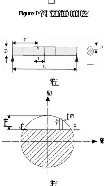
Figure 1 shows the components of a rotating system including the rotor shaft, the rigid disc and the bearings. In general the rotor can be discretized by finite elements. The equation of motion of the complete rotor system in a fixed coordinate system can be written as:
} ) t ( F { } { ] K [ . } { ] ) ( C [ ..
} { ] M
[ δ+ Ω δ + δ = (1)
inertia are included in the mass matrix [M]. Matrix [C] consists of the gyroscopic moments and the bearing damping. Stiffness matrix [K] considers the stiffness of the shaft elements including cracked shaft element and the bearing stiffness. For the analysis of cracked rotor system, the cracked element will be replaced with the element, which is initially uncracked. The excitation force {F} in Equation 1 consists of the weight of the disc and the unbalance forces due to the disc mass m and eccentricity e.
3. MODELING OF OPEN CRACKS
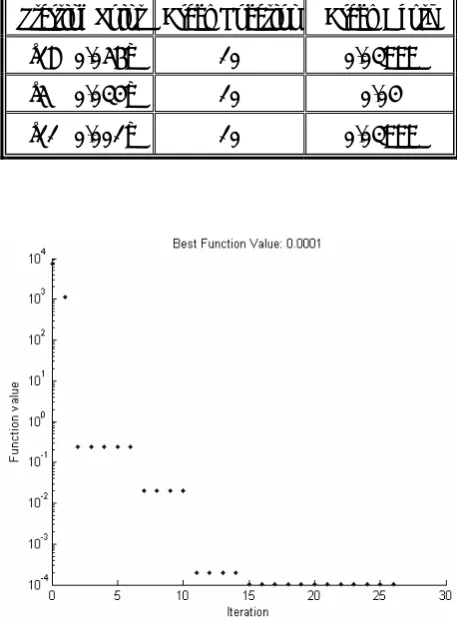
It has been shown that due to fatigue, lateral cracks will be initiated at high speed in heavy duty rotors in the long run. Combinations of permanent and dynamic stresses, as well, are responsible for the cracks that are initiated by fatigue. Generally, shafts that are under bending or reciprocating stresses are more susceptible to initiate cracks. Consider a rotor-bearing system with a crack as shown in Figure 2. The rotor is discretized into finite beam elements. Each element has two nodes with four degrees of freedom at each node; displacement and rotation in both x and z directions (see Figure 3). The shaft element is loaded at one node with two shear forces and two bending moments. The details of crack cross-section with crack of depth a are shown in Figure 2b.
The presence of crack in the shaft element increases its flexibility. With the shearing action neglected and by using the strain energy, the flexibility coefficients for a section of an element without crack can be derived as [9],
⎥ ⎥ ⎥ ⎥ ⎥ ⎥ ⎥ ⎥ ⎥ ⎥
⎦ ⎤
⎢ ⎢ ⎢ ⎢ ⎢ ⎢ ⎢ ⎢ ⎢ ⎢
⎣ ⎡
− − =
EI l 0 0 EI 2
2 l
0 EI
l EI 2
2 l 0
0 EI 2
2 l EI 3
3 l 0
EI 2
2 l 0 0 EI 3
3 l
0
C (2)
Where, l, E and I are lengths, Young's modulus and
moment of inertia for a shaft section, respectively. Equation 2 is the inverse of the stiffness matrix of a section of an uncracked element of Figure 2a.
Figure 1. The rotor components.
(a)
a
-bb
x z
α
dx
(b)
Figure 2. (a) Rotor-bearing system with cracked and uncracked
elements, (b) cross-section of cracked element.
The brief discussion on flexibility matrix of cracked section as given in [9] is repeated here for the beam element with 4 d.o.f. per node. A crack on a beam element introduces considerable local flexibility due to strain energy concentration in the vicinity of the crack tip under load. According to the principle of Saint-Venant, the stress field is affected only in the region adjacent to the crack. The element stiffness matrix may be regarded as unchanged under certain limitation of element size, except for the cracked element. Because of discontinuity of deformation in the cracked element, it is difficult to find out an appropriate shape function to express the kinetic and elastic potential energies. However, the additional stress energy of a crack has been studied thoroughly in fracture mechanics and the flexibility coefficient, expressed by a stress intensity factor, can be easily derived by means of Castigliano's theorem in the linear-elastic range.
Paris equation gives the additional displacement i
u due to the crack depth of α in the ith direction as:
⎥ ⎥ ⎦ ⎤ ⎢ ⎢ ⎣ ⎡ ∫ α α α ∂ ∂ = 0 d ) ( J i P i
u (3)
Where J(α) is the strain energy density function and Pi is the corresponding load. The strain energy density function is:
⎥ ⎥ ⎥ ⎦ ⎤ ⎢ ⎢ ⎢ ⎣ ⎡ ⎟ ⎟ ⎠ ⎞ ⎜ ⎜ ⎝ ⎛ ∑ = + ⎟ ⎟ ⎠ ⎞ ⎜ ⎜ ⎝ ⎛ ∑ = + ⎟ ⎟ ⎠ ⎞ ⎜ ⎜ ⎝ ⎛ ∑ = = 2 4 1 j KIII,j m
2 4
1 j KII,j 2
4
1 j KI,j '
E 1 J
(4) Where m=(1+ν), E′=E for plane stress and
) 1 /( E
E′= −ν2 for plane strain. Also, Kij is the stress intensity factor for mode i, i = I, II and III, and index j represents the load direction. The details of the derivations of Equations 3 and 4 are presented in [9]. The local flexibility due to the crack per unit width by definition is given as:
⎥ ⎥ ⎦ ⎤ ⎢ ⎢ ⎣ ⎡ ∫ α α α ∂ ∂ ∂ = ∂ ∂ = 0 d ) ( J j P i P 2 j Pi u ij
c (5)
After integration along the width 2b of the crack one obtains: ⎥ ⎥ ⎦ ⎤ ⎢ ⎢ ⎣ ⎡ ∫ α α α ∫ − ∂ ∂ ∂ = 0 dx d ) ( J b b j P i P 2 ij
c (6)
The values of stress intensity factors (SIF) in Equation 6, for a strip of unit thickness are:
0 2 , I K 1 , I
K = =
2 / 1 ) 2 x 2 R )( 4 R / 3 P 4 (
3= π −
σ ) h / ( 2 F 3 3 , I
K =σ πα α
x ) 4 R / 4 P 4 (
4= π
σ ) h / ( 1 F 4 4 , I
K =σ πα α (7a)
0 4 , II K 3 , II K 1 , II
K = = =
) 2 R /( 2 kP
2= π
σ ) h / ( II F 2 2 , II
K =σ πα α (7b)
0 4 , III K 3 , III K 2 , III
K = = =
) h / ( III F 1 1 , III
K =σ πα α
) 2 R /( 1 kP
1= π
σ (7c)
) h 2 /( πα = λ 2 / 1 ) / tan ( ) h / ( III
F α = λ λ (8)
Where k=6(1+ν)/(7+6ν) is the shape factor for a circular cross-section and h=2 R2−x2 . By combining Equations 4, 6, 7 and 8, one can obtain the dimensionless compliance coefficients as:
x d z d ) h ( b
0 0 III 2 F z 4 ) 2 v 1 /( 11 ERc 11
c =π − = ∫ ∫α
x d z d ) h ( b 00 II 2 F z 14 . 3 ) 2 v 1 /( 22 ERc 22
c =π − = ∫ ∫α
x d z d ) h ( b
0 0 2
2 F ) 2 x 1 ( z 64 ) 2 v 1 /( 33 c 3 ER 33
c =π − = ∫ ∫α −
x d z d ) h ( 2 F ) h ( b
0 0 1
F 2 x 1 z x 64 ) 2 v 1 /( 34 c 3 ER 43 c 34 c
∫ ∫α −
= − π = = x d z d ) h ( b
0 0 1
2 F z 2 x 32 ) 2 v 1 /( 44 c 3 ER 44
c =π − = ∫ ∫α (9)
Where
R / x
x= ,z=z/R, h=z/h, b=( 2aR−a2)/R and ) R / a 1 ( 2 x
1− − −
=
α .
In order to calculate the integrals in a simple manner, almost all the researchers assumed that the integration boundary of Equations 9 is constant in crack depth and is equal to α≈a/R. However, the integration boundary of Equations 9 varies with crack depth (i.e. α= 1−x2−(1−a/R)). Although such an assumption makes the calculation of integrals more difficult, this will improve accuracy of the results in calculating the natural frequencies
and mode shapes of the rotating systems. It can be shown that the elements of stiffness matrix calculated by the proposed integration scheme differ about 15 % from those calculated by conventional methods. The changes in the stiffness matrix cause a change of about 10 % on the fundamental frequency of systems [18].
The flexibility matrix due to the crack presence is then calculated as:
⎥ ⎥ ⎥ ⎥ ⎥ ⎦ ⎤ ⎢ ⎢ ⎢ ⎢ ⎢ ⎣ ⎡ = R / 44 c R / 43 c 0 0 R / 34 c R / 33 c 0 0 0 0 R 22 c 0 0 0 0 R 11 c 0 F 1 c
C (10)
Where F0 =πER2/(1−ν2), R is the shaft radius and ν is the Poisson’s' ratio. The total flexibility matrix for the cracked section is the sum of the flexibility matrix of the cracked and uncracked elements and can be expressed as:
[ ]
⎥⎦⎤ ⎢⎣ ⎡ + ⎥⎦ ⎤ ⎢⎣ ⎡= C0 Cc
C (11)
Finally, the stiffness matrix of the cracked element can be calculated as:
[ ]
[ ] [ ] [ ]
T C 1 T T cK = − (12)
Where [T] is the transformation matrix defined as:
⎥ ⎥ ⎥ ⎥ ⎥ ⎥ ⎥ ⎥ ⎥ ⎥ ⎥ ⎦ ⎤ ⎢ ⎢ ⎢ ⎢ ⎢ ⎢ ⎢ ⎢ ⎢ ⎢ ⎢ ⎣ ⎡ − − − − − = 1 0 0 0 0 1 0 0 0 0 1 0 0 0 0 1 1 0 0 l 0 1 l 0 0 0 1 0 0 0 0 1
T (13)
The crack is assumed to only affect the stiffness. While assembling Equation 1, the stiffness matrix of a cracked element [Kc] will replace the stiffness matrix of the same element prior to cracking to result in the global stiffness matrix [K].
containing shafts, disks, bearings and cracks was developed and used in this study. The finite element code was validated by means of several standard examples and by comparing its results with those obtained from MECOS software.
4. A REVIEW ON DIRECT SEARCH METHODS
Direct search is a method for solving optimization problems that does not require any information about the gradient of the objective function. As opposed to the traditional optimization methods that use information about the gradient or higher derivatives, in the direct search algorithm, a set of points around the current point is searched for objective function with a lower value. The direct search may be used to solve problems for which the objective function is not differentiable, stochastic, or even non-continuous [19].
There are two direct search algorithms called the generalized pattern search (GPS) and the mesh adaptive search algorithm (MADS). In both algorithms, a sequence of points gradually gets closer to the optimal point. At each step, the algorithm searches a set of points, called a mesh, around the current point. The mesh is formed by adding the current point to a scalar multiple of a set of vectors called a pattern. If the pattern search algorithm finds a point in the mesh that improves the objective function at the current point, the new point becomes the current point at the next step of the algorithm [20].
The MADS algorithm is a modification of the GPS algorithm. The algorithms differ in how the set of points forming the mesh is computed. The GPS algorithm uses fixed direction vectors whereas, the MADS algorithm uses a random selection of vectors to define the mesh.
5. USING PATTERN SEARCH AND FEM TO DETECT SHAFT CRACK
Shaft crack is a very dangerous and frequent fault in rotating machines. Direct detection methods such as ultrasonic and infrared radiation, have
some weakness due to existence of highly noised signals. Therefore, it seems that detecting crack location and depth is an inverse problem and not easy to tackle. Conceptually, computational techniques for the solution of inverse problems usually consist of two parts: numerical discretization methods for ill-posed objects (e.g. the shaft with cracks) and iterative procedures that are used to search for the actual geometrical configuration (e.g. the cracks location and size) [15].
In this study, the discretization stage was made with the finite element method. A finite element code was developed for analyzing a rotor system with open cracks.
5.1. Objective Function
Definition of objective function is the first step in solving an inverse problem. As mentioned in Section 3, the presence of cracks in the shaft element increases the flexibility and hence reduces the natural frequencies. The resulting changes in the natural frequencies can be used to detect shaft cracks. In this research, the first four natural frequencies of the shaft were used. Interested readers can find techniques of measurement of the natural frequencies in [21]. To detect crack, the natural frequencies of the cracked shaft must be measured and imported to the code. This code has the ability of finding natural frequencies of the cracked shaft for different arrangement of the crack location and size. The objective function which must be minimized is defined as:∑
= − ′
= 4
1 i
2 ) i f i f (
G (14)
Where fi is the measured natural frequencies and i
f′ is the calculated natural frequencies by the code.
The design vector consists of two variables; crack location and crack depth. The element number which contains crack indicates the crack location. For example, if element 11 of the shaft contains crack and the length of each element is 0.1 m, the crack location varies between 1m and 1.1m. Fine mesh can produce more accurate result and hence, shorter range.
examined. The first case is a simply supported cracked rotor as shown in Figure 4. Length of the rotor is 2.1 m which is divided into 21 elements. Therefore, the accuracy of crack location is 0.1 m. The rotor is made of steel and has a 6 cm diameter. To check the proposed algorithm, a 4 cm crack was held on the tenth element of the rotor. Table 1 tabulates the first four natural frequencies of the cracked and uncracked rotor.
For the uncracked rotor, the symmetric condition in x and z directions causes the same frequencies in these directions. The natural frequencies of the cracked rotor were imported to the code. Two sets of constraints exist: the number of elements which varies from 1 to 21 and the crack depth that varies from 0 to the shaft diameter. The pattern search algorithm needs one point as a starting point. Here, the obtained starting point is [18 0.056] which means a 0.056 m depth crack in element 18. The solution [10 0.03999] agrees well with the desired result.
To test the efficiency of the proposed method, the effects of different starting points on the results were checked. In this way, two other starting points were selected and imported to the code. The results of these runs are presented in Table 2. From the results of the table, it can be concluded that the crack detection algorithm is powerful and robust.
According to Equation 14, it is obvious that the global minimum of the function G is zero. Therefore, accuracy of the resulting point can be evaluated by the criteria that if the value of the objective function is very close to zero, the results are acceptable; otherwise, the starting point must be changed. Figure 5 shows the value of the objective function for the first starting point in different iterations.
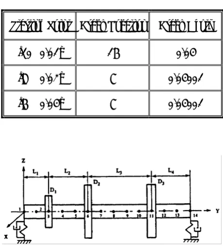
Next, the crack location has been changed and put in element 16. Table 3 shows the results for different starting points.
Although the algorithm detected the crack depth correctly, the resulted crack location for the 2nd and 3rd starting point is not correct. To find the source of the error, the natural frequencies of rotor with cracks in elements 16 and 7 were obtained as: x = 16 → f = [20.38 26.84 83.83 106.65] x = 7 → f = [20.38 26.84 83.85 106.66]
Figure 4. A simple rotor system.
TABLE 1. The First Four Natural Frequencies.
Uncracked Rotor Cracked
Rotor Natural
Frequency (Hz)
27.3 18.47
1
27.3 26.74
2
107.8 102.18
3
107.8 107.59
4
TABLE 2. Crack Location and Depth for Different Starting Points.
Crack Depth Crack Location
Starting Point
0.03999 10
[18 0.056]
0.04 10
[5 0.034]
0.03999 10
[11 0.001]
Figure 5. The variation of objective function value in each
It can be seen that the corresponding natural frequencies in these two cases are very close and this closeness is the motive of error. The reason of this closeness is the symmetry of rotor in this example. The second example is depicted in Figure 6. This rotor is not symmetric. The rotor was divided into 13 elements with equal length of 0.1m. The angular velocity of rotor is 25000 rpm. The mechanical and geometrical properties of the rotor are tabulated in Tables 4 and 5 [22].
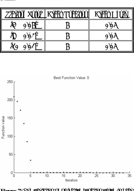
In this case, a 5 cm crack is located on element 6. The first four natural frequencies of the cracked rotor are 47.63, 65.18, 156.04, and 181.84 Hz. The natural frequencies of the rotor without crack are 56.3, 66.63, 160.26 and 192.78 Hz.
The results of the code for different starting points are shown in Table 6.
As can be seen, the proposed algorithm predicted the crack location and depth successfully. The objective function value is zero for all starting points. Figure 7 shows the objective function value for the first starting point in different iterations. It is noted that a crack deep enough, about 1/4 of radius, will change the vibration characteristics of the rotor [23].
6. CONCLUSIONS
In this paper, a methodology based on the pattern search method was introduced and used for solving crack detection problems. First, based on the finite element method, a computer code was developed which can calculate the natural frequencies of cracked rotors. A more accurate integration scheme was used to calculate the stiffness matrix of elements with the crack. It can be shown that the elements of stiffness matrix calculated by the proposed integration method differ about 15 % from those calculated by the conventional method. The changes in the stiffness matrix cause a change of about 10 % on the fundamental frequency of the system.
Next, using the measured natural frequencies of the cracked rotor and the outputs of the FE code, a fitness function was constructed. The main advantage of this function is that the global minimum of this function is zero. So, the accuracy of the resulting point can be evaluated easily.
TABLE 3. Results for Various Starting Points.
Crack Depth Crack Location
Starting Point
0.04 16
[10 0.01]
0.04001 7
[8 0.02]
0.04001 7
[6 0.04]
Figure 6. The schematic illustration of rotor.
TABLE 4. Geometrical and Physical Properties of the Rotor.
13 Number of Elements
14 Number of Nodes
10 Shaft Diameter (cm)
200 × 109 Modulus of Elasticity
of Shaft and Discs
) m N
( 2
7800 Density of Shaft and
Discs )
m Kg
( 3
0.2, 0.3, 0.5, 0.3 L1, L2, L3, L4 (m)
7 xx 5x10
k = 7
zz 7x10
k =
Bearing Stiffness
) m N (
2 xx 5x10
c = 2
zz 7x10
c =
Bearing Damping
To check the efficiency and robustness of the proposed method, a simple cracked rotor system and a model of an industrial turbine were considered. The results of the crack configuration showed that this algorithm is feasible and this method has the potential ability to detect cracks. The effect of the starting point on the performance of the algorithm was also investigated. It was shown
that only in the symmetric rotors, the starting point may lead to false results and in real industrial rotors, which are asymmetric, and the starting point has no effect on the results.
7. REFRENCES
1. Lee, C.W. and Kwon, K.S., “Crack Detection in Rotating Machinery by Modal Testing”, IMechE, Vol.
31, (2000), 535-543.
2. Wauer, J., “On the Dynamics of the Cracked Rotors: A Literature Survey”, Applied Mechanics Review, Vol.
43, (1990), 13-17.
3. Gasch, R., “A survey of the Dynamic Behavior of a Simple Rotating Shaft with a Transverse Crack”,
Journal of Sound and Vibration, Vol. 160, (1993),
313-332.
4. Sekhar, A.S. and Prabhu, B.S., “Crack Detection and Vibration Characteristics of Cracked Shafts”, Journal
of Sound and Vibration, Vol. 157, No. 2, (1992),
375-381.
5. Wauer, J., “Modeling and Formulation of Equations of Motion for Cracked Rotating Shafts”, International
Journal of Solids and Structures, Vol. 26, (1990),
901-914.
6. Gasch, R., “Dynamic Behavior of a Simple Rotor with Cross-Sectional Crack”, IMechE Conference Publication, Vol. 170, (1976), 123-128.
7. Dimarogonas, A.D. and Papadopoulos, C.A., “Vibration of Cracked Shafts in Bending”, Journal of Sound and
Vibration, Vol. 91, (1983), 583-593.
8. Papadopoulos, C.A. and Dimarogonas, A.D., “Coupled Longitudinal and Bending Vibrations of a Rotating Shaft with an Open Crack”, Journal of Sound and
Vibration, Vol. 117, (1987), 81-93.
9. Dimarogonas, A.D. and Paipetis, S.A., “Analytical Methods in Rotor Dynamics”, Applied Science Publishers, New York, U.S.A., (1983).
10. Papadopoulos, C.A., “Torsional Vibrations of Rotors with Transverse Surface Cracks”, Comput. Struct, Vol.
51, No. 6, (1994), 713-718.
11. Henry, J.A., “Monitoring Rotating Machinery to Detect the Growth of Rotor Cracks, in Colloquium on the Design Applications and Maintenance of Large Industrial Drives”, IEE Conference Publication, Vol. 170, (1978),
37-44.
12. Kujath, M. and Li, J., “Diagnosis of Fractures in Machinery”, Proceeding 4th International Modal Analysis
Conference, Los Angeles, Union College, New York,
U.S.A., (1986).
13. Kujath, M., “Detection of Sudden Changes of Modal Parameters in Machinery”, The International Journal of
Analytical and Experimental Modal Analysis, Vol. 2,
(1988), 131-137.
14. Kujath, M., “Identification of Fractures in Rotors”,
Proceedings International Conference on Rotor Dynamics, JSME, Tokyo, Japan, (1986), 379-383.
15. He, Y., Guo, D. and Chu, F., “Using genetic Algorithms
TABLE 5. Dimensions of Disks.
3 2
1 Disk
0.06 0.05
0.05 Width (m)
0.05 0.05
0.05 Inner Radius (m)
0.2 0.2
0.12 Outer Radius (m)
TABLE 6. Crack Location and Depth for Different Starting Points.
Crack Depth Crack Location
Starting Point
0.05 6
[4 0.06]
0.05 6
[8 0.02]
0.05 6
[10 0.01]
Figure 7. The variation of objective function value in each
and Finite Element Methods to Detect Shaft Crack for Rotor-Bearing System”, Mathematics and Computers
in Simulation, Vol. 57, (2001), 95-108.
16. Suresh, S., Omkar, S.N., Ganguli, R. and Mani, V., “Identification of Crack Location and Depth in a Cantilever Beam using a Modular Neural Network Approach”, Smart Materials and Structures, Vol. 13,
(2004), 907-915.
17. Yukio. I., Tsuyoshi, I. and Tadashi, M., “Finite Element Analysis of the Cracked Rotor with Periodic Excitation”,
Dynamics and Design Conference, Vol. 513, (2004),
1-6.
18. Silani, M. and Ziaei Rad, S., “Forced Responses and Free Vibration Analysis of Rotating Systems with one
and Multi Open Cracks”, Inter Noise Conference,
Istanbul, Turkey, (2007).
19. Rao S.S., “Engineering Optimization, Theory and Practice”, 3rd ed., John Wiley and Sons, Inc, New York,
U.S.A., (1995).
20. MATLAB Help, Ver. 7.2.0.232, Math Works, (2006). 21. Ewins, D.J., “Modal Testing: Theory, Practice, and
Application”, Research Studies Press, Hertfordshire, England, (2000).
22. Lalanne, M. and Ferraris, G., “Rotor Dynamics Prediction in Engineering”, 2nd ed., John Wily and Sons, New York, U.S.A., (1998).