Efficient Hardware/Software Implementation of LPC
Algorithm in Speech Coding Applications
Mohamed Atri, Fatma Sayadi, Wajdi Elhamzi, Rached Tourki
Electronics and Microelectronics Laboratory, Faculty of Sciences, University of Monastir, Monastir, Tunisia. Email: {Mohamed.Atri, Rached.Tourki}@fsm.rnu.tn, {Sayadi_Fatma, Elhamziwajdi}@yahoo.fr
Received January 2nd,2011; revised September 14th, 2011; accepted November 3rd, 2011
ABSTRACT
The LPC “Linear Predictive Coding” algorithm is a widely used technique for voice coder. In this paper we present different implementations of the LPC algorithm used in the majority of voice decoding standard. The window-ing/autocorrelation bloc is implemented by three different versions on an FPGA Spartan 3. Allowing the possibility to integrate a Microblaze processor core a first solution consists of a pure software implementation of the LPC using this core RISC processor. Second solution is a pure hardware architecture implemented using VHDL based methodology starting from description until integration. Finally, the autocorrelation core is then proposed to be implemented using hardware/software (HW/SW) architecture with the existing processor. Each architecture performances are compared for different data lengths.
Keywords: Linear Predictive Coding; System on Programmable Chip; FPGA; Co-Design
1. Introduction
Applications such as cell phones, hearing aids, and digi- tal audio devices are applications with stringent con- straints such as area, speed and power consumption. These complex applications can be well addressed by Systems on Programmable Chip (SoPC). Modern Field Program- mable Gate Arrays (FPGAs) contain many resources that support DSP applications such as embedded multipliers, Multiply Accumulate (MAC) units and processor cores. The motivation for the introduction of such processor core comes from the idea that most FPGAs contained within an embedded system require interaction level with an external processor. Moving this processor onto the chip allows the FPGA and the processor to communicate without the bottlenecks associated to communicating with off-chip devices. Several programmable logic ma- nufacturers offer FPGAs platform. Altera, Atmel, Xilinx [1] propose devices that integrate hardware cores of processors such as ARM, MIPS and PowerPC CPUs and/ or allow instantiation of soft processor such as Micro- Blaze from xilinx and Nios from Altera, DSP and mi- crocontroller cores like PicoBlaze. In this work, we pro- pose different implementation modes of the Linear Pre- dictive Coding (LPC) algorithm used in the majority of voice decoding standard. According to its criticality of the LPC algorithm and its reusability property, the win- dowing/autocorrelation bloc seems a good candidate for IP design. This block is thus implemented by three dif-
ferent versions on an FPGA. The system performances have been evaluated with a prototyping board integrating embedded Microblaze processor with peripherals on a FPGA Spartan 3. This flexible system enables to reduce overall product cost, achieve target performances, elimi- nate risk of obsolescence and finally use industry stan- dard software development [2]. Pure software imple- mentation of the LPC is first proposed using MicroBlaze soft core RISC processor. Second pure hardware archi- tecture is implemented using VHDL description. Finally, the autocorrelation core is then proposed to be imple- mented using HW/SW architecture with the existing processor. Each architecture performances are compared for different data lengths. The remainder of this paper is organized as follows: Section 2 gives a necessary back- ground on the LPC analysis and the autocorrelation algo- rithm. The starter board and implementation tools are detailed in Section 3. Section 4 introduces the Micro-blaze processor. Each architecture implementation details are depicted in Section 5. Section 6 presents the imple-mentation results. Finally Section 7 concludes the paper and details some future works.
2. LPC Algorithm Overview
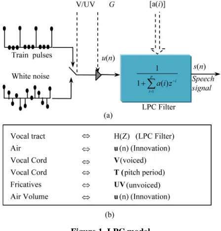
passage of an excitation signal through a filter. This mo- del called linear predictive coding (LPC) is given in the case of an auto-regressive signal [3,4] and is presented in
Figure 1(a).
The correspondence between the real world and the mathematical models is given in Figure 1(b) [5,6], This
is equivalent to say that the input-output relationship of the filter is given by:
G u z
s zA z
(1)
In order to evaluate the LPC model, the linear regres- sion has to be solved, that is to say the coefficients a(i) of the recursive filter are to be found. If the operations in- volved by the LPC analysis are summed-up, this task includes five sub-tasks:
A windowing + an autocorrelation, The Levinson Durbin algorithm [7,8], A LP to LSP Conversion [9,10], A LSP Quantization [11],
Interpolation & conversion of the LSP coefficients.
3. Implementation Approach
In order to extract an efficient hardware/software parti- tioning, the processing and communication complexity of the LPC algorithm was evaluated in [12]. A survey of the distribution of the different processing complexity parts of the algorithm is necessary. The aim is to first know to what extent it can be interesting to achieve some blocks into hardware rather than software and, secondly, if this blocks can be used in other applications in order to jus- tify their specification as a reusable component.
3.1. Hardware/Software Partitions
The windowing/autocorrelation block and the LSP Quan- tization block are the most critical blocks. The technique used for the quantization is specific to the standard G729. In fact the LSP coefficients are quantized using the LSF (line spectral frequency) representation in the normalized frequency domain (0, π). Then the quantization is achieved using a two-stage vector quantizer [13]. In fact, rather than doing the computations, most voice coder use a sim- ple look-up table. This solution can be efficiently imple- mented into software. This is the way we have imple- mented this block. The other significant sub-block, the autocorrelation sub-block, is data computation dominated. We thus decided to centres round this block. In fact the critical operations of the majority of digital signal pro- cessing algorithms are usually the convolution or product accumulations. A dedicated arithmetic unit achieving a multiplication and accumulation is generally used to cope with this problem; it is called a MAC.
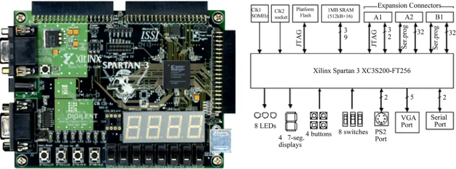
[image:2.595.310.534.86.320.2]To achieve our objectives, we have used the Spartan™-
Figure 1. LPC model.
3 Starter Kit provided by Xilinx [2].
3.2. Board and Embedded Processor
The Spartan-3 Starter Board from Xilinx provides a po- werful, self-contained development platform for designs. It features a 200 K gate Spartan-3, on-board I/O devices, and one MicroBlaze fast asynchronous SRAM, making it the perfect platform to experiment with any new design, from a simple logic circuit to an embedded processor core. The board also contains a Platform Flash JTAG- programmable ROM, so designs can easily be made non- volatile. The Spartan-3 Starter Board is fully compatible with all versions of the Xilinx ISE tools. It ships with a power supply and a programming cable, so designs can be implemented immediately with no hidden costs.
Figure 2 shows the Spartan-3 Starter Kit board, the
main components and features are quoted below: 200,000-gate Xilinx Spartan-3 XC3S200 FPGA; 1M-byte of Fast Asynchronous SRAM;
3-bit, 8-color VGA display port; 9-pin RS-232 Serial Port; PS/2-style mouse/keyboard port;
Four-character, seven-segment LED display; Eight slide switches;
Eight individual LED outputs;
Figure 2. Spartan-3 starter board.
The Spartan 3 starter kit which combines XC3S200 of Spartan 3 FPGA family, provides an environment for designing an embedded and reconfigurable system based on the MicroBlaze softcore processor.
The MicroBlaze embedded soft core is a Reduced In- struction Set Computer (RISC) optimized for implemen- tation in Xilinx FPGAs. With few exceptions, the Mi- croBlaze can issue a new instruction every cycle, main- taining single-cycle throughput under most circum- stances. Unlike any other hard processors which are ac- tually implemented in the FPGA at a transistor level, the soft core is an IP block written in HDL and is imple- mented in the free resources of an FPGA. Therefore it is configurable by choosing the components that would be included in the system.
According to the application type, MicroBlaze proce- ssor can be configured in several ways to save power or area. MicroBlaze processor provides four bus connec- tions, namely the Local Memory Bus (LMB), the On- chip Peripheral Bus (OPB), the Fast Simplex Link (FSL) and the Xilinx Cachelink (XCL). The LMB is a dedi- cated bus for MicroBlaze and on-chip block RAM con- nection. The OPB is a CoreConnect IBM standard bus [16] and gives the capability to connect variety of avail- able IP blocks and peripherals.
The FSL has a FIFO-based interface and it provides a connection between a custom hardware to assist particu- lar application. Lastly the XCL interface provides a link between MicroBlaze processor and data and instruction caches.
4. Solution Space Exploration
The LPC block input is assumed to be a 16 bits PCM signal. Two pre-processing functions are applied before the encoding process signal scaling, and high-pass filter- ing. The scaling consists of dividing the input by a factor 2 to reduce the possibility of overflows in the fixed-point
implementation. The high-pass filter serves as a precau- tion against undesired low-frequency components. A se- cond order pole/zero filter with a cut-off frequency of 140 Hz is used.
The Linear Prediction (LP) is performed once per speech frame using the autocorrelation method with a 30 ms asymmetric window. Every 80 samples (10 ms), the autocorrelation coefficients of windowed speech are computed and converted to the LP coefficients using the Levinson algorithm.
The LP analysis window consists of two parts: the first part is half a Hamming window and the second part is a quarter of a cosine function cycle. The window is given by:
2π
0.54 0.46 cos 0, ,199
399
2π 200
cos 200, , 239
159 lp n n W n n n (2)
The windowed speech is given by the following equation:
lp
0, , 239s n W n s n n (3) and is used to compute the autocorrelation coefficients as follow:
2390 0 0 239 239
1 1 0 239 238
0 9
9 9 0 239 230
n k
r k s n s n k
r S S S S
r S S S S
k
r S S S S
4.1. Software Solution
In software version, LPC Algorithm is a full software implementation mapped onto the MicroBlaze processor. Data is accessed through the data cache and comes from the external SRAM.
The system architecture of a MicroBlaze implemen- tation is shown in Figure 3. The LPC algorithm is re-
coded in ANSI C and stored in on-chip BRAM. The size of BRAM is set to 64 K which is the maximum size that one MicroBlaze processor can have on the Spartan-3 XC3S200 [2] FPGA.
The connection between Block RAM and MicroBlaze processor is through ILMB [15] (Instruction-side Local Memory Bus) and DLMB [15] (Data-side Local Memory Bus). The DOPB [15] (Data-side Onchip Peripheral Bus) is used for connecting the following peripherals:
UART [15], OPB Timer [14], and Debug Module [15]. The HyperTerminal is a communication program used on a PC workstation to print the result received at PC’s serial port. The Xilinx Microprocessor Debug (XMD) tool of Xilinx Embedded Development Kit (EDK) is used to debug the system from the PC workstation. The elapsed-time of running the C program in the Block RAM presented later is achieved by starting and stopping the OPB Timer peripheral before and after a specific code segment. Execution time results for each partition are summarized in Table 1.
4.2. Hardware Solution
The second architecture is a pure hardware implementa-tion of the algorithm. This architecture makes use of an autocorrelation core that will be presented later in HW/ SW architecture section. It also makes use of a windowing core in order to reduce the generation of side lobes in the frequency spectrum. To be done two blocks are imple- mented: multiplier block and a 256 word 16 bit ROM as shown in Figure 4.
To minimize development time Xilinx’s CORE gene- rator has been used to produce the simple arithmetic op- erators and memory required by this windowing block.
The used ROM is constructed in the Spartan III FPGA using the ISE’s CORE generator. In fact the CORE gene- rator can be used to produce devices ranging in comple- xity from simple arithmetic operators and delay elements to complex building-blocks such as digital signal decod- ers, processing filters, multiplexers, transformers, FIFOs, and memories.
The content of this memory is defined by supplying an input coefficient precalculated starting from the Equation (2).
The final system is built around the windowing core and the autocorrelation computation presented in section II.B. Figure 5 summarizes the global hardware system
design. Table 2 presents execution time for each block.
UART
Debug OPB
Dual Port BRAM
Microblaze Processor
ILMB
DOPB
DLMB
HyperTerminal PC WorkStation
Figure 3. Microblaze system architecture.
ROM
Multiplier RST
Addr
Data_out
Signal CLK
Out Data_in
Data_in
Figure 4. Windowing block architecture.
Windowing
Autocorrelation RST
CLK
Signal
Data_in
Start
RDY
Data_out
Figure 5. Global hardware architecture.
Table 1. Profiling results with pure software.
Execution time in µs
Function n = 10 n = 80 n = 100 n = 150 n = 200 n = 240 Windowing 16.67 133.33 166.67 250 333.33 400 Autocorrelation 533 2983 3683 5433 7183 8633
Table 2. Profiling results with pure hardware implementation.
Execution time in µs
This global design is implemented using the Spartan 3 Xilinx board. The RTL specification is made compatible with most of FPGA design tools for an efficient compo- nent reuse. This is also the reason why we have used hand- written RTL MAC rather than on-chip one.
The specification can be parameterized according to the window size and the data width (word length). It is also parameterized according to the value of index k of the r(k) autocorrelation coefficient equation.
4.3. Hardware/Software Implementation
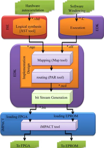
In this version, we proposed a HW/SW high-performance implementation. As shown in software version, profiling algorithm shows that the autocorrelation could be im- plemented into hardware block. Thus we have applied an EDK based design flow for the implementation of the windowing/autocorrelation algorithm. In fact The EDK is an integrated environment for HW & SW co-design.
[image:5.595.57.274.404.711.2]One of the biggest challenges of this architecture was to get a System On a Programmable Chip (SOPC) with LPC algorithm. This means implementing both software and hardware components. As the target device, a Spar- tan-3 starter kit was chosen due to its flexibility, great promise of integrating both the hardware and software co-designs into one flow as shown in Figure 6.
Figure 6. Embedded development tool flow overview.
The soft core Processor MicroBlaze is used in a stand- alone mode to run a software program (written in C) which is loaded into BRAM.
The whole design flow, except the simulation execu- tion, is covered by Xilinx EDK and ISE software pack- ages. The Adding a Processor System to and FPGA De- sign module introduces the two design flows of a hard- ware system available in EDK: the XPS flow and the ISE flow. The procedure involved in each flow is illustrated
Figure 7. This flow summarizes our system design. The
speech signal is stored in the SRAM. The MicroBlaze processor achieves the windowing computation then sends the results to the Autocorrelation hard Block to compute the autocorrelation coefficients.
In this architecture the user logic is an Autocorrelation core which is coded in VHDL. It should be noted that linear prediction in speech processing has an important characteristic since it is determinist. Taking this charac- teristic into account it is usually possible to apply some parallelism techniques in order to increase the perform- ance of the implementation.
The Microblaze achieves the windowing computation then sends the result to the user logic. The FPGA com- putes the autocorrelation coefficients.
In our case the autocorrelation computation can be split in many sub-tasks independently executable since the set of computations can be written as in Equation (4).
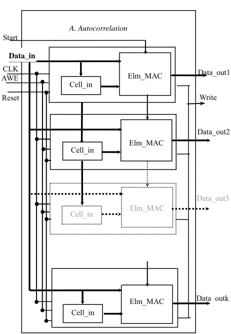
Systolic arrays are very well suited to compute this kind of computation [17]. Applying the dependence me- thod [18], a linear systolic array (Figure 8) has been spe-
cifically designed for the autocorrelation computation with 10 MAC-based cells as described in Figure 9. For a
clock cycle i, every MAC(k) reads S(i) and S(i – k) and adds to its previous result S(i) * S(i – k). At the first clock edge MAC0 performs the multiplication S(0)·S(0). At the second one, MAC0 performs S(0)·S(0) + S(1)·S(1), and MAC1 performs the multiplication S(1)·S(0). At the third clock edge MAC0 performs S(0)·S(0) + S(1)·S(1) + S(2)·S(2), MAC1 S(1)·S(0) + S(2)·S(1) and MAC2 S(2)·S(0), and so on.
Finally, the ten autocorrelation coefficients r(0)…r(9) are provided after 240 clock periods.
This linear array achieves an efficient speed-area trade off with a parallelism rate of 10 (10 useful multiplica- tions and accumulations each clock cycle on average). A single clock is used to control this array. Furthermore, since this systolic array is linear (one dimensional array), the data communication interface is also easy to be (re) used.
Systolic arrays are very interesting for reusable com- ponents. This kind of array uses elementary cells locally interconnected and is basically regular.
Figure 7. OPB integration.
start
MAC0 MAC1 MAC2 MAC9
S(0) ………….S(240)
r(0) r(1) r(2) r(9)
Multiplier/ R
R
Data_In Start
CLK AWE
Reset
Cell_in Elm_MAC
Cell_in Elm_MAC
Cell_in
Elm_MAC
Cell_in Elm_MAC
Data_out1
Data_out2
Data_out3
Data_outk
A. Autocorrelation
Write Data_in
Figure 9. Hardware MAC architecture.
tion coefficient equation r(k).
The size of the proposed array (number of MAC cells) does not depend on the maximum value of the n index: this value only sets the number of input data, i.e. it sets the size of the hamming window. The proposed array can thus be easily used in many speech coders (GSM 160, G723, G729 240, etc.) [13,20].
Another interesting point of this autocorrelation im- plementation is that it doesn’t need intermediate data to be stored in a RAM. Additional memory accesses and control are thus avoided.
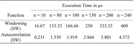
The profiling of the HW/SW architecture is shown in
Table 3. It can be seen that the gain in execution time is
considerable as soon as the number of samples increases. In fact the autocorrelation core reduces the execution time by a ratio close to 96%.
Figure 8. Linear systolic array for the autocorrelation.
[image:6.595.57.288.345.679.2]Table 3. Profiling results after using hardware accelerator.
Execution Time in µs
Function n = 10 n = 80 n = 100 n = 150 n = 200 n = 240 Windowing
(SW) 16.67 133.33 166.66 250 333.33 400 Autocorrelation
(SW) 0.231 1.539 1.919 2.866 3.801 4.572
5. Results and Discussions
In this paper, three different architectures were proposed for realizing a windowing and autocorrelation computa- tion. These three architectures are implemented on Spar-tan-3 board.
[image:7.595.63.283.410.563.2]Using a window sized of 240 and a word length of 16 bits, the profiling results of each architecture are shown in
Figure 10. It is clear that the pure hardware implementa-
tion results in a significant speedup over the software implementation and rather HW/SW version.
The hardware resources for the implementation are summarized in Figure 11. The SW architecture resource
requirements are fixed with the value of n all versions of the algorithm are implemented in software and changing n requires just modifying the C code and recompiling it. We note that the hardware version, use more silicon surface then HW/SW version and then over consumption.
Figure 10. Profiling results for different architectures.
Figure 11. Resource utilization for different architectures.
The results show that the increased hardware resource requirements are not excessive when compared to the basic MicroBlaze core.
6. Conclusions and Future Works
In this paper three different architectures were proposed to implement the LPC algorithm. All of them are aimed for voice decoding process using the Xilinx board based MicoBlaze soft processor. A comparison between the three architectures shows that using a hardware architec-ture coupled with a MicroBlaze processor in mixed ar-chitecture reduces the number of cycles required to per-form the most critical operation by about 96%.
Also, the HW/SW approach allows the designer to fo- cus only on the development of the VHDL core descrip- tion without taking into account communication prob- lems. This goal is reached due to the definition of an au- tomated flow IP-Cores integration into a complete sys- tem architecture without requiring the user interaction. Using a HW/SW architecture gives a significant speed up results with a moderate area and lower flexibility. Thus, such a design will enable us to achieve an optimum tra- deoff between speed and flexibility permitting to make a complete system on programmable chip (SoPC). In fact the proposed approach represents a general computing model which can be extended too many different appli- cations like G729 coder.
REFERENCES
[1] U. M. Baese, “Digital Signal Processing with Field Pro-grammable Gate Arrays,” 2nd Edition, Springer-Verlag, Berlin, 2004.
[2] Spartan-3 FPGA Starter Kit Board User Guide, UG130 (v1.2), 2008.
[3] H. M. Zhang and P. Duhamel, “Doubling Levinson/Schur Algorithmand Its Implementation,” Proceedings of In-ternational Conference on Acoustics, Speech, and Signal Processing, Glasgow, 23-26 May 1989, pp. 1115-1118.
doi:10.1109/ICASSP.1989.266628
[4] B. S. Atal and M. R. Schroder, “Linear Prediction Analy-sis of Speech Based on Pole Zero Representation,” Jour-nal of Acoustic Society of America, Vol. 64, No. 5, 1978,
pp. 1310-1328. doi:10.1121/1.382117 [5] http://www.data-compression.com
[6] http://www.speech.cs.cmu.edu/comp.speech/
[7] P. Delsarte and Y. Genin, “The Split Levinson Algorithm,”
IEEE Transactions on Acoustics, Speech and Signal Pro- cessing, Vol. 34, No. 3, 1986, pp. 470-478.
doi:10.1109/TASSP.1986.1164830
[8] R. Hagen and P. Hedelin, “Spectral Coding by LSP Fre-quencies—Scalar and Segmented VQ-Methods,” IEE Pro- ceedings-I, Communications, Speech and Vision, Vol. 139,
Syn-thesis Methods Developed at ECL in NTT—From LPC to LSP,” Speech Communication, Vol. 5, No. 2, 1986, pp. 199-215.
[10] R. Salami, C. Laflamme, J. P. Adoul and A. Kataoka, “Design and Description of CS-ACELP: A Toll Quality 8 Kb/s Speech Coder,” IEEE Transactions on Speech and Audio Processing, Vol. 6, No. 2, 1998, pp. 116-130.
doi:10.1109/89.661471
[11] P. Zador, “Asymptotic Quantization Error of Continuous Signals and the Quantization Dimension,” IEEE Transac-tions on Information Theory, Vol. 28, No. 2, 1982, pp.
139-149. doi:10.1109/TIT.1982.1056490
[12] F. Sayadi, E. Casseau, M. Atri, M. Marzougui, R. Tourki and E. Martin, “G729 Voice Decoder Design,” The Jour-nal of VLSI SigJour-nal Processing, Vol. 42, No. 2, 2006, pp.
173-184. doi:10.1007/s11265-005-4180-y
[13] ITU-T, “Coding of Speech at 8 kbit/s Using Conjugate Structure Algebraic Code Excited Linear Prediction (CS-
ACELP),” ITU-T Recommendation G729 (03/96). [14] EDK Concepts, Tools & Techniques, XTP013 EDK, 2008. [15] Microblaze Processor Reference Guide (01/17/08). [16] M. Maaref, “Creating an OPB IPIF-Based IP and Using It
in EDK,” Xilinx, XAPP967 (v1.1), 2007.
[17] E. Casseau and D. Degrugillier, “A Linear Systolic Array for LU decomposition,” Proceedings of the 7th Interna-tional Conference on VLSI Design, Calcutta, 1994, pp.
353-358.
[18] C. Tayou, P. Quinton, S. V. Rajopadhye and T. Risset, “Derivation of Systolic Algorithms for the Algebraic Path Problem by Recurrence Transformations,” Parallel Com- puting, Vol. 26, No. 11, 2000, pp. 1429-1445.
doi:10.1016/S0167-8191(00)00039-9