Abstract— Geometric modelling is one of the methods for determination of the mass-inertial parameters of the different segments of the body, as well as of the body as a whole. It can be in addition used for determination of the body mass-inertial positions in different positions specific when a person performs a given activity including those in everyday life like walking, driving a car, relaxing at home in a convenient chair, but also in sports, in entertainment, etc., including even position of interest for NASA for planning the space activities of astronauts. The current article presents data on the geometric and mass-inertial characteristics of the human body based on a 16-segmental 3D model for some of the above-mentioned problems. We present both a brief review of some of our results, report some additional measurements needed for improving the geometrical modelling and outline some suggestions for the improvement and future development of the model. The so developed model is oriented towards application in medicine (orthopaedics and traumatology), rehabilitation robotics, computer simulations, sports and fields such as simulation of human behaviour in space, ergonomics, criminology, and other areas.
Index Terms—Biomechanics, body segment parameters,
CAD design, mass-inertial characteristics
I. INTRODUCTION
HE analysis of the human body geometric and mass-inertial parameters is of decisive importance in human motion analysis. . One of the first studies of mass, volume, and centre of mass of male cadavers are those of [1], [2]. In the ’60s and ’70s, several studies have reported anthropometric and mass-inertial parameters for the segments of the human body of elderly male cadavers [3],
Manuscript received April 06, 2019. The financial support by the Bulgarian National Science Fund: Contract DN-07/5 “Study of anthropometric and mass-inertial characteristics of the Bulgarian men and women via mathematical models of the human body” is gratefully acknowledged.
G. S. Nikolova is with the Institute of Mechanics, Bulgarian Academy of Sciences, Acad. G. Bonchev Str. Bl. 4, 1113 Sofia, Bulgaria (corresponding author phone: + 359-878-548842; fax: +359-2-870-74-98; e-mail: gergana1973@ gmail.com).
D. M. Dantchev is with the Institute of Mechanics, Bulgarian Academy of Sciences, Acad. G. Bonchev Str. Bl. 4, 1113 Sofia, Bulgaria (e-mail: [email protected]).
V. K. Kotev is with the Institute of Mechanics, Bulgarian Academy of Sciences, Acad. G. Bonchev Str. Bl. 4, 1113 Sofia, Bulgaria and the University of National and World Economy, Student Town, UNWE, 1700, Sofia, Bulgaria (e-mail: [email protected])
A. B. Kazakoff is with the Institute of Mechanics, Bulgarian Academy of Sciences, Acad. G. Bonchev Str. Bl. 4, 1113 Sofia, Bulgaria (e-mail: [email protected]).
[4], [5]. Of course, much more involved, but obviously much more important is the study of these characteristics for living people. The investigation in that direction for living male individuals have been based on the following methods: immersion and cast method [6], [7], gamma mass scanning [8], [9], geometrical modelling [10], [11], [12]. In the current study, we utilize an approach based on geometrical modelling.
When one represents via a mathematical model the human body, or a combination of its segments, the following problems must be solved:
1) Proper body decomposition – definitions of the anthropometric points defining the segments and the corresponding characteristic lengths.
2) Generation of a proper 3D model that includes the decision which segment of the body shall be modelled with what geometrical body.
3) Analytical determination of the properties of the segments of interest like mass, the centre of mass, moments of inertia using the mathematical properties of the 3D bodies involved.
4) Determination of the parameters like lengths of the corresponding segments by using data from anthropological measurements, as well as from measurements of the density of segments.
5) Generation of a computer realization of the 3D model with the data determined in the previous point.
6) Verification of the computer-generated model via comparison of the data obtained from the determination of the human body mass properties by using analytically derived results with those obtained based on the computer realization.
7) Determination of the characteristics of interest of a given part of the body, or the body as a whole, using the computer realization for, say, special positions and movements for which the analytical calculation would be time-consuming, cumbersome, or difficult.
In the current article, we will be concerned with the above mentioned seven points of that recipe for studying the mass-inertial properties of the human body. The achievement of these goals is crucial for the trustworthy prolongation of the general recipe towards a reasonable computer realization. As one of the potential practical goals of the study one can think of obtaining data needed for the design of devices, say upper human limb manipulator, aimed to help disabled people, having problems with the movement of their upper limbs, to determine the mass-inertial characteristics of the
Basic Results and New Data for Future
Development of the 16-Segmental 3D Model of
the Human Body
Gergana S. Nikolova, Daniel M. Dantchev, Vladimir K. Kotev and Alexander B. Kazakoff
human body of the average male and female in several body positions for space exploration as classified by NASA, to analyse human walking during the 8 phases of human gait cycle, in accordance with the literature, using 3D CAD software.
II. THE MODEL
In the current investigation, the model consists of 16 segments: head + neck, the upper part of the torso, the middle part of the torso, the lower part of torso, thigh, shank, foot, upper arm, forearm, and hand. All segments are assumed to be relatively simple geometrical bodies – see Fig.1. We suppose full body symmetry with respect to the sagittal plane, i.e., complete ‘‘left–right’’ symmetry. The decomposition of the body segments is made according to anthropometric points used in [8]. The mathematical model of the human body is described in details in [13].
The geometrical data needed is taken from a detailed representative anthropological investigation of the Bulgarian population [14] performed during the period 1989–1993. A total of 2435 males and 2855 females were measured. We take the average values found in the above investigation and design a model, which represents the so defined “average” Bulgarian male. The segments are modelled by means of geometrical forms similar to those in [10], but with the following modifications: (1) the torso is subdivided into three instead of two parts; (2) the torso upper part is approximated by means of a right reverted elliptical cone, while it is an elliptical cylinder in [10]; (3) according to [15], we specify both middle and lower torso modelled as an elliptical cylinder and an elliptical cylinder +reverted elliptical cone, respectively (in [10], these two segments are grouped together and modelled as an elliptical cylinder). Take notice that the torso lower part is defined here exactly as in [15]: it extends from omphalion to
iliospinale, with a plane passing through the iliospinales and
concluding an angle of 37o with the sagittal plane. All segments of both the lower and upper extremities are assumed to be cone frustums and the hand is modelled as a sphere. Once the geometrical parameters of the segments are determined, one can analytically obtain all the other characteristics of interest, such as volume, mass and moments of inertia.
III. SOMERESULTS
After determining the mass inertial parameters of the segments, one can also study the corresponding characteristics of the body as a whole assuming the body to be in a given position of interest. In order to achieve this goal, we have performed a realization of the model in the CAD system – SolidWorks. We have verified the computer realization by comparing the results it delivers for the mass inertial parameters of the segments of the body with those reported in [13]. The basic positions of the body have been classified long ago in the literature – see, e.g., [16], [10], [17], [5], [18]. One normally considers eight principal body positions. Here, due to the lack of space, we will present data for two of these positions: the so-called standing position – see Fig. 2a, and the so-called “Mercury configuration” – see Fig. 2b.
(a) (b)
Fig. 2. (a) Standing position: Subject stands erect with the head oriented in the Frankfort plane and with arms hanging naturally at the sides as when measuring; (b) Mercury configuration: Same as sitting position, except 1000 back-thigh angle, thigh-leg angle 1120, forearm parallel to thigh.
Table 1 contains the data for the so-called standing position for the principal moments of inertia, total mass, and height. Table 1 also provides a comparison with the data we have obtained for the average Bulgarian male with the corresponding data taken from the literature. Table 1 includes the data for the average height and mass of person in the corresponding study. The 50% and 95% marks in the data of Hanavan [10] and NASA [18] mean that the corresponding percent of measured data is below the value reported in the table. The coordinate system for the results reported in [5], [10], [16], [18] as well as the units used there, have been converted to the ones used in present investigation.
In Table 2 data for the principal moments of inertia for the so-called “Mercury Configuration” position is given.
The inspection for both body positions shows a reasonably good agreement between our results and those previously reported in the literature. Additional information for more body positions can be found in [19], [20], [21], [22].
[image:2.595.313.543.260.436.2]The investigation of mass-inertial parameters of human extremities is an important issue of human motion biomechanics.
[image:2.595.46.286.285.446.2]TABLE I STANDING POSITION
Characteristic NASA
Ref. [18]
Chandler
Ref. [5]
Santchi
Ref. [16]
Hanavan
Ref. [10]
Our data
50% 95% 50% 95%
IXX [kg.cm2x103] 14.4 18.5 17.2 12.7 9.1 14.1 9.7
IYY [kg.cm2x103] 129.2 163.4 118.9 116.0 116.2 161.9 105.3
IZZ [kg.cm2x103] 144.5 182.3 134.0 129.5 122.3 171.1 112.0
Center of mass [cm] 80.2 84.7 72.3 78.7 80.0 83.8 74.6
Total mass [kg] 82.2 98.5 65.2 75.5 73.4 90.9 72.5
Height [cm] 179.9 190.1 172.1 176.3 175.5 185.7 171.5
TABLE II
MERCURY CONFIGURATION
Inertial moments
NASA
Ref. [18]
Santchi
Ref. [16]
Hanavan
Ref. [10]
Our data
50% 95% 50% 95%
IXX
[kg.cm2x103] 19.5 22.6 17.9 17.35 25.8 19.9 IYY
[kg.cm2x103] 95.5 1 21.3
8
4.7 82.6 115.1 78.4 IZZ
[kg.cm2x103] 82.2 101.8 74.1 80.4 112.8 82.0
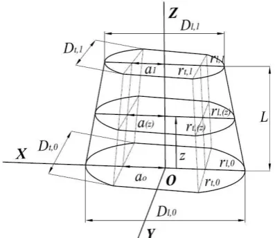
A method for determining the mass-inertial parameters of the upper and lower arm, thigh and shank of the human body using 3D geometrical modelling is presented below. The method is based on our own anthropometric measurements of 100 Bulgarian men and women that complement the representative anthropological investigation [14] of 2855 females and 2435 males of the Bulgarian population aged 30-40 years. We improve the 16-segmental mathematical model of the human body described in [13] by modelling the upper arm, lower arm, thigh and shank with versions of right elliptical stadium solids instead of using the frustum of a cone. More specifically i) the upper arm and thigh are represented by an elliptical solid with the base (proximal end) being circular; ii) the lower arm and the shank are considered to be right elliptical solids (see Fig.3).
Fig. 3. A right elliptical stadium solid used to model the upper and lower arm.
Let us immediately stress that one of the consequences of modelling these segments via right elliptical stadium solids is the lack of the “left-right” symmetry for the inertial moments of these segments. The last symmetry was
preserved in [13] and is usually also present in most of the geometrical models of the human body we are aware of. In [13] the main part of the geometrical data needed to determine the geometrical parameters of the segments of the body is taken from a detailed representative anthropological investigation of the Bulgarian population [14]. Unfortunately, the data collected does not include all the data needed to model the thigh, shank, upper and the lower arm as right elliptical solids. For that reason, we made our own complementary anthropometric measurements of these segments on an additional 100 Bulgarians - 50 men and 50 women, all of which inhabitants of the large city (Sofia). From each group 20 are scientists while the other 30 are personnel from the pharmaceutical company – management and workers. For group of 50 male subjects the body mass index (BMI) is 25.1 kg/m2, with standard deviation (SD) 3.6 kg/m2. The corresponding data for the group of scientists are BMI 24.5 and SD = 3.4, while for the personnel of pharmaceutical company one has BMI 24.5 and SD = 3.7, accordingly. For the group of all 50 female subjects, BMI = 20.6 kg/m2, SD = 2.9 with BMI for the group of scientists being 20.9 (SD = 2.9) and BMI for the group of personnel of pharmaceutical company is 20.7 (SD = 3.3). The comparison demonstrates that BMI is practically equal for two separate subgroups of men and women, correspondingly. Therefore, a different type of modelling of the segments it is not enforced. In the anthropometric measurements performed data forDl, Dt and Lcir have been collected. We shaped upper arm (acromion-radiale) as an elliptical solid with the base (proximal end) being circular. We measured the axillary circumference of the upper arm. We calculated the radius RSH of the base of the upper arm by using this circumference. For elbow (distal end) of the upper arm, we measured the epicondylar diameter of the humerus (Dl,0), the diameter perpendicular
to the humerus (Dt,0)and the upper arm circumference
across epicondyles (Lcir). All vertical lengths of the
segments ( )L are taken from [14]. The lower arm
(radiale-stylion) is approximated by stadium solid. The parameters
for its proximal end are the above-mentioned dimensions (distal end of the upper arm). For the wrist (distal end) of the lower arm (see Fig. 1, but turned upside down) we measured the breadth of radio-ulnar joint(Dl,1), the
thickness in the middle of the radio-ulnar joint perpendicular to its breadth (Dt,1) and the radio-ulnar joint
[image:3.595.58.257.519.691.2]thigh circumference, one can find the thigh radius RTH. For the length of the thigh, we use the real anthropometric length defined via the distance between tibiale and
iliospinale. The measured knee parameters (distal end of
thigh) are: subepicondilar diameter of the femur (Dl,0),
sagittal diameter perpendicular to subepicondilar diameter of femur (Dt,0) and knee circumference across epicondyles
(Lcir). The shank (tibiale-sphyrion) is modelled as a stadium solid. The parameters for modelling its proximal end are the above-mentioned dimensions (distal end of the thigh). The parameters measured for the ankle are: transversal supramalleolar diameter(Dl,1), saggital
supramalleolar diameter perpendicular to the transversal
,1
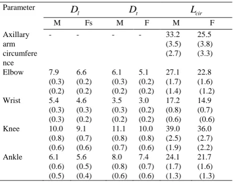
[image:4.595.44.277.381.563.2](Dt ) and the shank circumference over malleoli (Lcir). The average data for the directly measured independent geometrical parameters described above, as well as their standard and mean deviations for males and for females, are summarized in Table 3, respectively.
TABLE III
THE AVERAGE VALUES OF THE DIRECTLY MEASURED INDEPENDENT PARAMETERS (CM) FOR MALES AND FEMALES. IN BRACKETS THE STANDARD (SD) AND MEAN DEVIATIONS (MD) ARE GIVEN. HERE Dl AND DtSHALL BE UNDERSTOOD AS
,0
l
D AND Dt,0FOR ELBOW AND KNEE AND AS Dl,1 AND
,1
t
D FOR WRIST AND ANKLE.
Parameter
l
D Dt Lcir
M Fs M F M F
Axillary arm circumfere nce
- - - - 33.2
(3.5) (2.7)
25.5 (3.8) (3.3)
Elbow 7.9 (0.3) (0.2) 6.6 (0.2) (0.2) 6.1 (0.3) (0.2) 5.1 (0.2) (0.2) 27.1 (1.7) (1.4) 22.8 (1.6) (1.2) Wrist 5.4
(0.3) (0.3) 4.6 (0.3) (0.2) 3.5 (0.3) (0.2) 3.0 (0.2) (0.2) 17.2 (0.8) (0.6) 14.9 (0.7) (0.6) Knee 10.0
(0.8) (0.6) 9.1 (0.7) (0.6) 11.1 (0.8) (0.7) 10.0 (0.8) (0.6) 39.0 (2.5) (1.9) 36.0 (2.7) (2.2) Ankle 6.1
(0.6) (0.5) 5.6 (0.5) (0.4) 8.0 (0.8) (0.6) 7.4 (0.7) (0.6) 24.1 (1.7) (1.3) 21.7 (1.6) (1.3)
With the data measured for Dl, Dt and Lcir, and having in mind the analytical properties of the stadium solid one can determine the values of a, rl and rt of the corresponding segments. These average values define the so-called average men and the average woman. The height and weight of the average man are 1.71.m and 77.7 kg, while for the average woman they are 1.58 m and 65.3 kg. The results obtained in this way are summarized in Tables 4 and 5 for males and for females, respectively.
TABLE IV
CALCULATED PARAMETERS, LENGTS AND DENSITIES FOR MALES.
Segment Parameters
0
a rl,0 rt,0 a1 rl,1 rt,1 L
Upper arm 3.7 0.3 3.0 - 5.3a 5.3a 30.9 1053 Lower arm 3.7 0.3 3.0 2.5 0.2 1.7 24.7 1100 Thigh 3.9 1.1 5.6 - 9.1a 9.1a 51.0 1062 Shank 3.9 1.1 5.6 1.4 1.7 4.0 37.2 1088 a The radius calculated by using the corresponding circumference.
TABLE V
CALCULATED PARAMETERS, LENGTS AND DENSITIES FOR FEMALES.
Segment Parameters
0
a rl,0 rt,0 a1 rl,1 rt,1 L
Upper arm
3.1 0.2 2.6 - 4.1a 4.1a 28.6 1053
Lower arm
3.1 0.2 2.6 2.2 0.1 1.5 21.9 1100
Thigh 3.9 0.7 5.0 - 9.5a 9.5a 47.9 1062 Shank 3.9 0.7 5.0 0.9 1.9 3.7 34.6 1088 a The radius calculated by using the corresponding circumference.
In additions, there also the lengths L (in cm) of the segments, according to [14], and densities ρ (in kg/m3) of the segments, according to [13], are given. Using the original experimental data measured and the analytical properties of the solid bodies involved in modelling the segments of the human body, we calculate the volumes, masses, the positions of the centres of the masses and the corresponding principal moments of inertia of the average Bulgarian man and woman. Note that by approximating a segment with a given geometrical body a given error in reproducing its mass is immediately generated. Obviously, better the geometrical approximation of the segments via solid bodies smaller the corresponding error. Deriving an analytical expression for the moments of inertia of right elliptical stadium solid and performing the corresponding numerics, the principal moments of inertia for the upper arm, lower arm, thigh and shank are calculated. Table 6 contains the so-obtained results for males, and Table 7 for females, respectively. More details can be found in [23], [24].
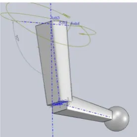
We paid specific attention to the generated model for the upper limb of the human body. We consider the limb as composed by three segments – elliptic stadium solids representing the upper and lower arm of the human, and a sphere, that models the hand. The proposed model is shall be helpful in engineering when designing devices aimed to help disabled individuals. It can predict data for the inertial parameters of a given male individual provided the corresponding easily measurable geometrical data for this individual are known. Using the model, we calculate the volume and mass, the centre of mass and the principal moments of inertia for the human body upper limb for two basic sub-cases: i) determination of these parameters for the separate parts of the upper limb: upper arm, lower arm and hand and ii) for the human upper limb as a whole. For the last, we used the computer realization of the model – see Fig. 4. In order to validate the accuracy of the program, we have performed a detailed comparison of the numerical results obtained within the program with the numerical evaluation of the analytical expressions that we have derived for the corresponding quantities.
TABLE VI
MOMENTS OF INERTIA OF THE BODY SEGMENTS THROUH THE CENTER OF MASS (KG.CM2) FOR MALES. Segment Zatsiorsky Ref. [15] Shan and Bohna Ref. [25] Nikolova and Toshev Ref. [13] Our data
IXX IYY IZZ IXX IYY IZZ IXX IYY IZZ IXX IYY IZZ
Upper arm 114.4 127.3 38.9 108.8 103.8 28.4 220.8 220.8 25.1 178.1 185.3 24.6
Lower arm 60.2 64.7 12.6 49.8 54.6 7.3 54.7 54.7 8.5 46.6 49.4 8.9
Thigh 1999.4 1997.8 413.4 1872.6 1879.9 420.6 1564.0 1564.0 307.7 2073.9 2183.3 287.7
Shank 371.0 385.0 64.6 357.3 408.9 88.3 231.9 231.9 34.0 337.0 363.9 52.9
[image:5.595.33.559.82.148.2]a The data are obtained by using the regression equations derived by [25] applied for the average Bulgarian male person.
TABLE VII
MOMENTS OF INERTIA OF THE BODY SEGMENTS THROUH THE CENTER OF MASS (KG.CM2) FOR FEMALES Segment Zatsiorsky Ref. [15] Shan and Bohna Ref. [25] Nikolova and Toshev Ref. [13] Our data
IXX IYY IZZ IXX IYY IZZ IXX IYY IZZ IXX IYY IZZ
Upper arm 80.7 92.3 26.2 88.6 87.0 19.6 123.5 123.5 15.8 90.9 93.8 9.6
Lower arm 39.7 40.9 5.3 29.9 31.8 4.2 34.6 34.6 4.0 23.7 22.7 4.3
Thigh 1647.3 1690.1 324.2 1111.1 1118.2 299.8 1714.7 1714.7 290.5 1676.6 1770.8 275.6
Shank 399.7 409.9 48.6 256.2 298.8 69.0 119.4 119.4 24.8 224.0 239.8 34.5
[image:5.595.46.558.179.260.2]a The data are obtained by using the regression equations derived by [25] applied for the average Bulgarian female person.
Fig. 4. SolidWorks media realization of the human upper limb model.
Fig. 5. The eight phases of the human gait cycle.
3D human body model in SolidWorks medium recreating phase 1 – initial contact and phase and the phases 5 – pre-swing of human gait cycle are shown in Figure 6.
Fig. 6. 3D human body model in SolidWorks medium in phase 1 – initial contact and in phase 5 – pre-swing.
IV. IDEASFORFUTUREDEVELOPMENTS In our future research, we plan to model body segments with more complex figures for some of the segments and to compose modified models of the entire body in which such elements are encompassed. Such modifications we mentioned above for the upper and lower limbs in which the modelling has been based on elliptic stadium solids. A model of the body as a whole, that involves such limbs is, up to now, not studied. Further improvements of the modelling of the upper and lower limb can be based on the so-called, fully elliptic stadium solids – see Figure 7. More details can be seen in [27].
Fig. 7.a) The cross-section of the lower and the upper arm. It consists of a rectangular region ℛ (light grey color) with horizontal length 2Rl and vertical one 2rt. On the top and the bottom of ℛ two semi-ellipsis, ℰt and
ℰb, are appended (the light red color). The semi-ellipsis ℰt and ℰb are with
major semi-axis Rland minor semi-axis Rt. Obviously, ℰR = ℰt⋃ ℰb is an
ellipse with semi-axis Rland Rt. In a similar way, one has two semi-ellipsis
ℰland ℰr(the light blue color)appended to the left and to the right-side of
ℛ with semi-axis rland rt. Thus, one has =ℛ ⋃ ℰR⋃ ℰr , where ℰr = ℰl ⋃ ℰr. b) The top down view of the upper-most and lowest cross-sections of
the lower part of the arm. The lowest cross section is with light red color, while the uppermost is in light green. The midpoints of all the cross-sections, marked by the red dots in the middle, do coincide – thus one arrives at the right fully elliptic stadium solid, shown in c), as the 3D body characterizing the lower arm. There it is shown a general view of the body with which we will be modelling the upper and lower arm of the upper limb. In this body at the bottom one thinks of a cross section 0
characterized with lengths and on the top, for , of a cross section 1 , with lengths . The height of the body, the
distance between and is . Let us note that here we have shown some specific realization with given values of the parameters. The dimension along to z axes in vertical direction is not in scale with the ones along x and
y in order to achieve better visibility.
[image:5.595.104.243.284.423.2] [image:5.595.316.543.452.530.2] [image:5.595.54.292.462.533.2]the previous ones. On shall study, of course, all the problems already studied within the previous simpler models. In doing so, a CAD realization of such a model shall be realized. One of the problems here is the verification of the computer-generated data for the model. For doing so, analytical expressions for the new geometric figures are needed. For example, one can derive expressions for
• the volume of the fully elliptic stadium solid
determine the position of centre of mass CM of the segment. Due to the symmetry one obviously has that the and coordinates of CM are equal to zero. The notation CM( ) used below then simply reminds that what one actually calculates is the coordinate of the centre of mass :
.
components of the tensor of inertia , and . The corresponding expressions are quite long and cumbersome and thus we refrain of explicitly writing it here. In order to determine the principal moment of inertia, we have to use Steiner’s theorem [28]
.
Another problem that needs a reasonable solution is to properly model the specific way in which the hip joints the lower part of the torso. The current modelling does not reflect the fact that the torso lower part is extended from
omphalion to iliospinale, with a plane passing through the
iliospinales and concluding an angle of 37o with the sagittal plane [15]. Our current attempts to resolve that issue leads to a more complicated biomechanical 3D model of the human body with 21 and more segment. Finally, better statistics for determining the parameters of the elliptic stadium solids and fully elliptic stadium solids is also highly desirable. We are currently working on these issues.
REFERENCES
[1] E. Harless, “Die statishen momente der menschlichen gliedmassen,”
Cl.d.konigl.Bayer, Akad.d.Wiss., vol. 8, 1860. W.-K. Chen, Linear Networks and Systems (Book style). Belmont, CA: Wadsworth, 1993, pp. 123–135.
[2] W. Braune and O. Fischer, “The center of gravity of the human body as related to the equipment of the German infantryman,” Treat. of the Math-Phys, vol. 26, 1889.
[3] W. T. Dempster, “Space requirements of the seated operator, WADC Technical Report 55-159,” Ohio, Wright-Patterson Air Force Base, 1955.
[4] C. E. Clauser, J. T. McConville and J. W. Young, “Weight, volume, and center of mass of segments of the human body, Technical Report AMRL-TR-69-70,” Ohio, Wright-Patterson Air Force Base, 1969. [5] R. F. Chandler, C. E. Clauser, J. T. McConville, H. M. Reynolds and
J. W. Young, “Investigation of inertial properties of the human body, Technical Report AMRL-TR-74-137,” Wright-Patterson Air Force Base, Ohio, 1975.
[6] R. Drillis and R. Contini, “Body segment parameters, Technical Report 1166.03, New York University, School of Engineering and Science, New York, 1966.,” New York, New York University, School of Engineering and Science, 1966.
[7] R. Contini, “Body segment parameters (pathological), Technical Report 1584.03,” New York, School of Engineering and Science, New York University, 1970.
[8] V. M. Zatsiorsky and V. N. Seluyanov, “The mass and inertia characteristics of the main segments of the human body,” in
Biomechanics VIII-B, H. Matsui and K. Kobayashi, Eds., IL, Human Kinetics, pp. 1152-1159, 1983.
[9] V. M. Zatsiorsky and V. N. Seluyanov, “Estimation of the mass and inertia characteristics of the human body by means of the best predictive regression equations,” in Biomechanics IX-B, D. Winter, R. Norman, R. Wells, K. Hayes and A. Patla, Eds., Human Kinetics, Champaign, IL, pp. 233–239., 1985.
[10] E. P. Hanavan, “A mathematical model of the human body, AMRLTR-64-102,” Ohio, Aerospace Medical Research Laboratories, Wright-Patterson Air Force Base, 1964.
[11] Y. H. Kwon, “Kwon3D motion analysis,” 1999. [Online]. Available: http://kwon3d.com
[12] M. R. Yeadon, “The simulation of aerial movement-II. A mathematical inertia model of the human body,” Journal of Biomechanics, vol. 23, pp. 67-74, 1990.
[13] G. Nikolova and Y. Toshev, “Estimation of male and female body segment parameters of the Bulgarian population using a 16-segmental mathematical model,” Journal of Biomechanics, vol. 40, pp. 3700-3707, 2007.
[14] Y. Yordanov, A. Nacheva, S. Tornjova, N. Kondova, B. Dimitrova and D. Topalova, Anthropology of the Bulgarian population at the end of the 20th century (30-40 years old persons), Sofia: Prof. M. Drinov Publishing House, 2006.
[15] V. M. Zatsiorsky, Kinetics of Human Motion, Champaign, IL.: Human Kinetics, 2002.
[16] W. R. Santschi, “Moments of Inertia and Centers of Gravity of the Living Human Body. AMRL TR 63-36.,” Wright-Patterson Air Force Base, Ohio, 1963
[17] H. T. Hertzberg, “Anthropometry of Flying Person-nel-1950. WADC TR 52-321,” Wright Air Development Center, Ohio, 1954.
[18] NASA-STD-3000, “The Man-System Integration Standards, Volume I, Section 3. Anthropometry and Biomechanics,” 2000. [Online]. Available: https://msis.jsc.nasa.gov/sections/section03.htm#3.2.1. [19] G. S. Nikolova, V. K. Kotev and D. M. Dantchev, “CAD modelling of
human body for robotics applications,” in Proceedings of International Conference on Control, Artificial Intelligence, Robotics & Optimization, IEEE Computer Society Conference Publishing Services (CPS), Prague, Czech Republic, 2007.
[20] V. K. Kotev, G. S. Nikolova and D. M. Dantchev, “Determination of mass-inertial characteristics of the human body in basic body positions: computer and mathematical modelling,” in EMBEC & NBC 2017, Tampere, Finland, 11-15 June, 2017, IFMBE Proceedings 65, Springer Nature , Singapore Pte Ltd., 2017.
[21] G. S. Nikolova, V. K. Kotev and D. M. Dantchev, “Computer and mathematical modelling of the female human body: determination of mass-inertial characteristics in basic body positions,” in Proceedings of the 7th International Conference on Simulation and Modeling Methodologies, Technologies and Applications (SIMULTECH 2017), SCITEPRESS, Madrid, Spain, 2017.
[22] G. S. Nikolova, V. K. Kotev and D. M. Dantchev, “CAD design of human male body for mass–inertial characteristics studies,” MATEC Web of Conferences, Vols. 145, 04005 2018, eISSN: 2261-236X, 2018.
[23] G. Nikolova, “Anthropometric measurements and model evaluation of mass-inertial parameters of the human upper and lower extremities,” in IFMBE Proceedings 29, Berlin, Heidelberg, 2010a.
[24] G. Nikolova, “Segmental Parameters of Bulgarian man within modified known human body model,” Journal of Theoretical and Applied Mechanics, vol. 40, no. 3, pp. 101-116, 2010b.
[25] G. Shan and C. Bohn, “Anthropometrical Data and Coefficients of Regression Related to Gender and Race. Applied Ergonomics, 34 (2003), 327–337.,” Applied Ergonomics, vol. 34, pp. 327-337, 2003. [26] G. S. Nikolova, V. K. Kotev, D. M. Dantchev and P. K. Kiriazov, “Basic inertial characteristics of human body by walking,” in
Proceedings of The 15th International Symposium on Computer Methods in Biomechanics and Biomedical Engineering and the 3rd Conference on Imaging and Visualization, CMBBE 2018, 26-29 March 2018, IDMEC © 2018, Lisbon, Portugal, 2018.
[27] G. S. Nikolova and D. M. Dantchev, “3D mathematical model for evaluation of the mass-inertial characteristics of the upper limb: Analytical results,,” in AIP Conference Proceedings 2025, 060002;, 2018.