Induction Motor Control With Small DC Link Capacitor Inverter Fed By
Three Phase Diode Rectifier
K S Manimala*1, D Srinivas Rao2
M.Tech Student, Department of EEE, KIET, Kakinada, India.1 Asst. Professor, Department of EEE, KIET, Kakinada, India.2
Abstract
This venture enhances the unwavering quality and power thickness of three stage variable speed drives by controlling presents a little film capacitor inverter based acceptance engine control . A hearty half and half engine controller is created to counteract execution corruption caused by the electrolytic capacitor-less inverter sustained by front-end diode rectifiers. The structure of the controller consolidates a model-based controller (MBC) and a hexagon voltage controlling controller (HVC). The MBC decides the order yield voltage with the convergence of the torque and rotor flux linkage charge. In the HVC mode, the order voltage vector is resolved just by the torque charge and the hexagon-formed inverter voltage limit. Fruitful utilization of the control approach is substantiated by a graphical and diagnostic implies that actually prompt a solitary voltage choice run the show. This paper additionally looks at the operation affectability under engine parameter floats to decide how to decouple its impact utilizing a voltage unsettling influence state-channel plan. This venture enhances the yield voltage and smoothening wave shapes by utilizing fluffy controller than PI controller. The outcomes checked through MATLAB/SIMULINK condition.
Index Terms—Front-end diode rectifiers, hexagon voltage controlling controller (HVC),model-based controller (MBC), little film capacitor inverter, three-stage variable speed drive.
I.INTRODUCTION
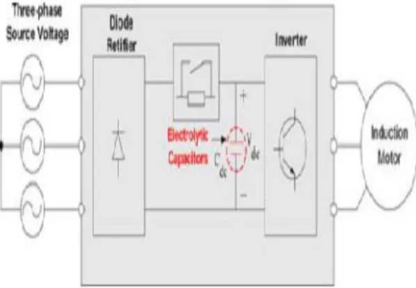
In ease three-stage variable speed drive applications, for example, warming ventilating-aerating and cooling (HVAC) frameworks, diode rectifiers are generally utilized as the front-end circuit for non regenerative ac–dc change as a result of their lower cost and higher dependability. In these sorts of minimal effort air conditioning drive frameworks, aluminum electrolytic
stifle the voltage spikes caused by spillage inductance and exchanging operations, as appeared in Fig. 1. Then again, the dc-transport capacitor is massive and overwhelming as well as one of the minimum dependable parts on different power electronic topologies.
Besides, the parasitic lead inductance can cause voltage spikes, which are a main consideration in the disappointment of energy electronic gadgets.
A disappointment review of switch mode control supplies revealed that electrolytic capacitors are in charge of the greater part of the breakdowns of an inverter. In this manner, there is expanding
Fig. 1 Three-phase diode rectifier and PWM inverter for IM drive.
Enthusiasm for the checking lifetime of electrolytic capacitors for solid and safe operation. Then again, disconnected checking procedures require extra Measurements and in addition from the earlier information for the reference show, which makes observing procedure entangled and troublesome. A formerly revealed online technique for assessing the capacitance can't be connected to inverters nourished by diode rectifiers.
goal to limit or decrease these detached Components on a dc transport. The concentration of most examinations has been on the most proficient method to diminish the dc-transport capacitor of three-stage beat width adjustment (PWM) rectifiers and single-stage diode rectifiers .
All past examinations were outfitted with a customary shut circle current controller to direct the air-hole torque and flux linkage of air conditioning engines. In any case, prompt current control in a little dc-transport capacitor inverter with the diode rectifier front-end is not direct in light of the fact that the dc-connect voltage and yield energy to the engine diminish intermittently because of the nonattendance of vitality stockpiling.
This quick dc voltage lessening drives the engine to be worked as often as possible in the field-debilitating district beneath a based speed. Thusly, the present control system turns out to be more confounded under voltage-restricted conditions in light of the fact that numerous target sub controllers, for example, field-debilitating, hostile to windup control, and over balance conspire, ought to be outlined deliberately in light of the mind boggling tradeoff between the sub control activities and current control elements .
Moreover, acknowledgment of the most extreme voltage usage comes up short on the grounds that a round voltage restrain is viewed as an operation limit rather than a hexagonal cutoff. This venture introduces a position sensor less vector-controlled acceptance engine (IM) drive framework coordinated into HVAC applications. The engine control is provided by a little dc-interface film capacitor inverter sustained by a three-stage diode front-end rectifier. A PI engine current-controller free control methodology is proposed to address the previously
mentioned difficulties by
joining.
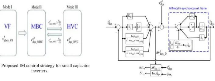
Fig.2 Proposed IM control strategy for small capacitor inverters.
A model-based controller (MBC) and a hexagon voltage controlling controller (HVC). The MBC finds the charge yield voltage with the crossing point of the torque and rotor flux linkage order. In the HVC mode, the summon voltage vector can be resolved essentially by the torque charge and the hexagon voltage limit. The MBC is performed under non constrained conditions and engine control is given consequently finished to the proposed HVC in the voltage deficiency district.
These voltage determination rules take into consideration the decision of a target voltage vector without PI control picks up, sub controllers, and eyewitnesses for shut circle control. The control system was executed on a 1.5-kW IM drive that was outfitted with a 20-μF film capacitor to affirm its attainability.
II.Design and Analysis of a Motor Controller
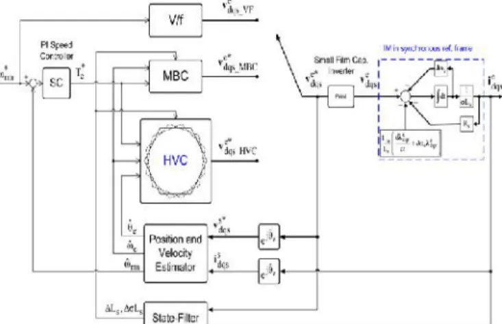
Fig. 2 demonstrates a piece graph of the proposed control technique for an IM utilizing an intricate vector portrayal. Here, v∗ abcs and ve∗ mdqs are the stator voltage summons in the abc-reference outline and the synchronous reference outline, separately, and Vdc means
Fig. 3. State-filter design for decoupling the parameter dependence.
Compensation of effects parameters and state filter were explained in reference[1].
Fig. 4. Overall control block diagram.
III.FUZZY LOGIC CONTROL
FLC determined by the set of linguistic rules. The
mathematical modeling is not required in fuzzy controller due to the conversion of numerical variable
into linguistic variables. FLC consists of three part: a.
Fuzzification, b. Interference engine, c. Defuzzification.
The fuzzy controller is characterized as; For each input
and output there are seven fuzzy sets. For simplicity a membership functions is Triangular. Fuzzification is
using continuous universe of discourse. Implication is
using Mamdani's "min" operator. Defuzzification is
using the "height" method. FLC block diagram as
shown in figure 2.
Fig. 5. Fuzzy Logic Controller
linguistic variables, using seven fuzzy subsets: NB(Negative Big), NM(Negative Medium), NS (Negative Small), ZE (Zero), PS (Positive Small),PM(Positive Medium) and PB (Positive Big). The partition of fuzzy subsets and the shape of membership function adapt the shape up to appropriate system. Input error E(k) and change in error CE(k) of values which is normalized by an input scaling factor as shown in table 1.
Table1:Fuzzy Rules
Fig.6 Input1 Membership function
In this system the input scaling factor is between -1 and +1 has design. The triangular shape of the membership function of this arrangement presumes that for any particular input there is only one dominant fuzzy subset . The input error E(k) and change in error C(k) for the FLC is given as
Fig.7 Input2 Membership function
Simulink Block diagram of Fuzzy controller:
Simulik results based on FUZZY controller:
CONCLUSION
motor-current-regulator-free control structure presents a smooth transition from the MBC under the unconstrained voltage region to the HVC when the voltage limit is encountered. The analytical solution leads to the dynamic voltage modification at each time step with respect to the available dc-bus voltage.
The algorithm can provide adequate results over a number of potential secondary upsets found in the current regulator-based control structure. The operation sensitivity under motor parameter drifts is also examined to decouple its influence using a voltage disturbance state filter. The test results clearly show that the proposed method can improve the inverter reliability without sacrificing the motor control performance.
This project improves the output voltage and smoothening wave forms by using fuzzy controller than PI controller .Simulation results verified through MATLAB/SIMULINK environment.
REFERENCES
[1] SeHwan Kim, Student Member, IEEE, and Jul-Ki Seok, Senior Member, IEEE” Induction Motor Control With a Small DC-Link Capacitor Inverter Fed by Three-Phase Diode Front-end Rectifiers” IEEE TRANSACTIONS ON POWER ELECTRONICS, VOL. 30, NO. 5, MAY 2015
[2] K. W. Lee, M. Kim, J. Yoon, S. B. Lee, and J. Y. Yoo,
“Condition monitoring of dc-link electrolytic capacitors in adjustable-speed drives,” IEEE Trans. Ind. Appl., vol. 44,
no. 5, pp. 1606–1613, Sep./Oct. 2008.
[3] M. L. Gasperi, “Life prediction modeling of bus capacitors in AC variablefrequency drives,”IEEE Trans. Ind. Appl., vol. 41, no. 6, pp. 1430–1435, Nov./Dec. 2005. [4] A. Layhani, P. Venet, G. Grellet, and P. J. Viverge,
“Failure prediction of electrolytic capacitors during
operation of a switchmode power supply,” IEEE Trans. Power Electron., vol. 13, no. 6, pp. 1199–1207, Nov. 1998.
[5] A. M. Imam, T. G. Habetler, R. G. Harley, and D. M.
Divan, “Real-time condition monitoring of the electrolytic capacitors for power electronics
applications,” inProc. IEEE Appl. Power Electron. Conf.,
2007, pp. 1057–1061.
[6] D. C. Lee, J. K. Seok, and J. W. Choi, “Online capacitance estimation of DC-link electrolytic capacitors for three-phase AC/DC/ACPWMconverters using
recursive least squares method,”Proc. Inst. Electr. Eng.—
Electr.
Power Appl., vol. 152, no. 6, pp. 1503–1508, Nov. 2005. [7] L. Malesani, L. Rossetto, P. Tenti, and P. Tomasin,
in the DC link,”IEEE Trans. Ind. Appl., vol. 31, no. 2, pp.
287–292, Mar./Apr. 1995.
[8] A. Yoo, S. K. Sul, H. Kim, and K. S. Kim, “ Flux-weakening strategy of an induction machine driven by an electrolytic-capacitor-less inverter,” IEEE Trans. Ind. Appl., vol. 47, no. 3, pp. 1328–1336, May/Jun. 2011. [9] K. Inazuma, H. Utsugi, K. Ohishi, and H.Haga, “High -power-factor single-phase diode rectifier driven by