Oezkaya et al. World Journal of Engineering Research and Technology
AN INTUITIVE SOFTWARE SYSTEM FOR THE MODELLING OF
THREE-DIMENSIONAL FEM TAPPING SIMULATIONS
Ekrem Oezkaya*, Till Haus and Dirk Biermann
Institute of Machining Technology, TU Dortmund, Dortmund 44227, Germany.
Article Received on 28/03/2019 Article Revised on 18/04/2019 Article Accepted on 08/05/2019
ABSTRACT
This paper presents the development of a software system,
implementing user-friendly methods for creating, solving and
evaluating three-dimensional tapping simulations without the necessity
of large experience in the field of Finite-Element-Method (FEM)
simulations. To process and solve tapping simulation models, external control of the
commercial FEM software DEFORM 3D was realized, although an application programming
interface does not exist. The novelty of this research study is the development of a control
algorithm channel, to decouple simulation processing steps from DEFORM 3D and
implement these in a developed simplified software system next to computing time reducing
procedures. It could be shown that complex FEM simulations, which are typically allocated
to research purposes, could be adapted for general industrial applications.
KEYWORDS: Finite Element Method (FEM); three-dimensional tapping simulation; software development; control algorithm channel; DEFORM 3D.
INTRODUCTION
The tapping process is one of the most complex cutting operations and the design of tool
geometry varies widely with the experience of tool manufactures (Lorenz, 1980). Although
tapping is a very common machining operation, it is one of the less comprehended cutting
processes in practice till today (Armarego and Chen, 2002). A variety of different radial,
World Journal of Engineering Research and Technology
WJERT
www.wjert.org
SJIF Impact Factor: 5.218*Corresponding Author
Ekrem Oezkaya
Institute of Machining
Technology, TU Dortmund,
process has not received much attention from research workers and the resulting torques and
forces are not fully understood yet (Chen and Smith, 2011).
Step by step, material from the core drilling wall is removed by the cutting edges, until the
last teeth of the tapping tool have fully cut the thread profile (Tengyun et al., 1999). The workpiece is conically formed due to the tool’s angle of lead, while the cutting edges
vertically move along a spiral course (Simmons et al., 2012). The tapping tool teeth following
the chamfer length are used to calibrate and guide the tool in cutting direction. The geometry
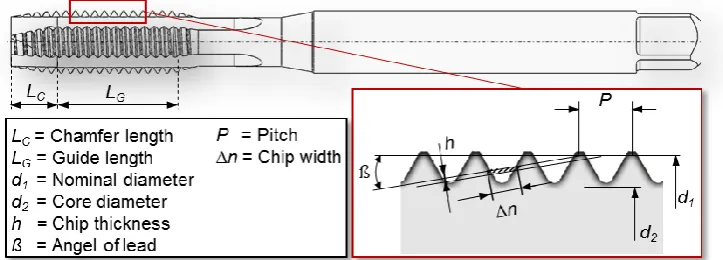
of the chamfer length specifies, whether the tool is usable for a certain application and influences the tool’s performance (Figure 1). The occurring torque during the tapping process
is generated via the chamfer length and increases due to the frictional torque of each tooth
(Ahn et al., 2003). The determination of the total resulting forces, which generate the total
torque, is therefore extremely difficult. Due the high complexity, the usage of simulations in
the modern industry remains restrictive until today.
Fig. 1: Tapping tool with its geometrical properties.
In 1931, Pampel firstly systematically investigated female thread borers with flat and round
thread profiles and observed, that tools with constant angles and larger core diameters have a
linear dependence (Pampel, 1931). Stoewer also investigated the torque by means of an
incision threading machine with three flutes and different chamfer length (Stoewer, 1932).
This study found, that a higher the rake angle and a smaller number of flutes result in a higher
torque, while in contrast to the tree-flute tools, the tapping tools with four flutes tended to
clamping and breaking. Schröder analyzed the relation between the cutting force and the
dimensions of the cross section and assumed, that the torque – provided that is a triangular
threaded profile – increases in form of a parable. The findings obtained at that time were
summarized by Schallbroch (Schallbroch, 1951). He showed, that the theoretical torque
measurements confirm these results, whereby the torque curve is strongly influenced by
different factors. The findings of Schallbroch were extended in the nomogram by Stieber for
prediction of torque (Stieber, 1955). Therefore, a tool performance evaluation could be
possible as it is for turning, milling, drilling etc. for common materials and threads with a
profile of 55° or 60°. Many influences such as the cutting angle, number of flutes, chamfer
length, core diameter and length of the thread were unconsidered and therefore the nomogram
does not have a high degree of scientific precision, but rather serves as a quick and fast
overview.
Due to growing requirements, the tapping tool with pointed teeth was investigated in the
chamfer length; the scientific investigation results were reported and summarized by Schmidt
et al. (Schmidt et al., 1962). Additionally, Dürr reported on the geometrical system and the
cutting properties of the tapping tool with pointed teeth in the chamfer length (Dürr, 1962).
Based on these findings, Pietzsch dealt with the optimization of the new tool (Pietzsch,
1962). Due to the shortening of the cutting edges in the second half of the chamfer part, the
load and thus also the total torque could be reduced and the chip removal improved.
Other researchers focused on the effect of force on each tooth. Thus the cutting forces were
divided into cutting, feed and passive forces by Zielinski (Zielinski, 1964). According to
Körsmeier, the important aspect, that the radial force is formed by the passive and the cutting
force, was missed (Körsmeier, 1974). For the first time, Körsmeier investigated the
geometrical relationships of tapping tools with positive and negative flutes on the thread
dimensions of M12 to M30 (Körsmeier, 1974). In this way, the design angles of the cutting
wedge could be calculated. A proportional relation to the static torque could also be derived
and confirmed for the cutting torque. In studies of tapping tools with smaller dimensions, the
boundary conditions change, so that further research is proposed. In this context, Hartkamp
investigated both the formation of built-up edges and the influence of increased cutting speed
and cooling lubricant during tapping (Hartkamp, 1977). Moreover, Hartkamp analyzed the
process on the tool cutting edges and came to the solution, that the tool life can only be
sensibly determined, when the interaction of material and tool has been thoroughly
process, force and torque characteristics of straight flute machine tapping tools (Armarego
and Chen, 2002). Under presupposed ideal conditions, Dogra et. al. developed a mechanistic
model for calculating the cutting forces during tapping, by focusing on the process errors and
borehole geometry (Dogra et al., 2002b). This model was incorporated into the methods
described by Dogra et. al. (Dogra et al., 2002a). They found that the most common errors are
the inconsistent adaptation of feed speed and thread pitch and that designs, which relieve the
tooth flanks, increase the quality of the thread profile and the tool life. Based on this
mechanistic model, Mezentsev et. al. developed a prediction model for the quality of the
thread, by means of a detection and estimation method of disturbances in the tapping process
(Mezentsev et al., 2002a). Mezentsev et. al. proposed a model-based method for tapping for
error detection with respect to the torque and the radial forces (Mezentsev et al., 2002b).
Another mechanistic model for the prediction of the torque and the axial force was developed
by Cao and Sutherland (Cao and Sutherland, 2002). For the simulated prediction of the feed
force and the torque during thread cutting, the general approach of Armarego (Armarego,
1998) provided the basic idea of deriving these from the orthogonal cutting data (Puzović and Kokotović, 2006). The importance and necessity of assessing the performance of the tapping
process is elaborated in various literature references and is, amongst others, confirmed by the
survey conducted by the the International Academy for Production Engineering (CIRP) in
1987 (Kahles, 1987). An extensive level of process understanding is required to control and
optimize the various parameters of a complex manufacturing process, which has not yet been
achieved in tapping.
Although the FEM simulation is nowadays commonly applied to analyze and improve
manufacturing processes by evaluating occurring forces, torques and temperatures, its usage
remains restricted for the tapping process. Due to the complex tool geometry, the process
cannot be described with a two-dimensional simulation model. A three-dimensional tapping
simulation with commercial FEM software requires a great amount of experience in the field
of FEM simulations and unreasonably large computing times, due to the complex tool
geometry, since the entire chamfer length of the tapping tool has to be considered, to acquire
a realistic torque value. For this reason, tool manufacturers develop new tapping tools in the
conventional manner of executing numerous experimental field tests after producing
according tool prototypes. In this paper, a novel developed FEM-based software system
(FBS) is presented (Oezkaya, 2016), which creates the possibility to evaluate the performance
tapping processes. The influence of tool geometry modifications on the torque could be
analyzed, so that the tapping tool could be optimized before the costly prototyping process. In
this way, the number of experimental tests could be reduced, leading to decreased usage of
engineering resources and development time, to sustainably support the tool construction
process.
Motivation and approaches
The aim of this research study was the development of a robust software system with an
according graphical user interface (GUI), suitable to create and evaluate three-dimensional
tapping simulations in an intuitive way. In conventional commercial FEM software, various
defining parameters, including properties for tool, workpiece, mesh, material, interactions
and boundary conditions, have to be considered to create a realistic simulation model. To
simplify this process, the required simulation parameters needed to be automatically provided
by the FBS. The numerical solving of the simulation model is still carried out through a
commercial FEM software, so that a control channel for the transfer of data between the FBS
and the commercial FEM software had to be ensured.
The choice of a suitable FEM software is an important factor to ensure a high simulation
quality, a large scope of analysis and correct simulation results, whereby the considered
software characteristics are the available features (functions and function groups), available
material models, as well as the utilized algorithms and solver techniques (Oezkaya, 2016).
The most commonly used commercial FEM software codes for the simulation of metal
forming are: DEFORM, Abaqus and AdvantEdge (Constantin et al., 2010; Gardner et al.,
2005). Since DEFORM was especially developed to simulate complex three-dimensional
forming and machining processes, this software presents a robust and potent FEM tool for
this investigation (Gardner and Dornfeld, 2006; Oezel, 2009). Next to implied Lagrange
calculations with iterative adaptive remeshing, the Euler-, Lagrange-, ALE and coupled
Euler-Lagrange-formulation (CEL) can be used for meshing procedures. Benefits and
disadvantages of DEFROM in comparison to AdvantEdge and ABAQUS are presented in
(Constantin et al., 2010; Gardner et al., 2005). Due to these benefits, the new FEM-System
to be simplified and automated. Since the graphical user interface (GUI) of DEFORM
requires a large amount time of experience to perform the various user interaction and
parameter modifications, a novel GUI was developed to realize a simplified process structure,
including the automated execution of numerous DEFORM algorithms. The creation of a
three-dimensional tapping simulation model was thereby implemented in an instructive way.
Furthermore, the three-dimensional tapping tool and workpiece geometries, as well as the
simulation results including the deformed workpiece geometry, were to be visualized within
the GUI, to provide a clear illustration of the simulation process.
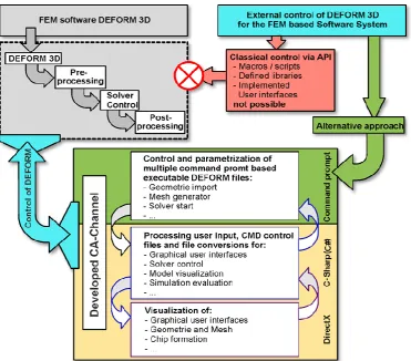
The lack of a typical API structure embedded within DEFORM, to easily and reproducibly
execute and modify DEFORM algorithms, presented the main challenge for the development
of the FBS. Typical API documentation usually includes the description of components such
as class definitions, constructors, methods etc. and necessary processing steps can be
retrieved by using an appropriate Dynamic Link Library (DLL). Since no comparable
solution could be found within DEFORM, a control channel with specific control algorithms
(CA-Channel) had to be developed (Figure 2).
Another reason for the restrictive usage of 3D FEM simulations for the tapping process is the
unacceptably high computing time due to the complex tool geometry, since the entire
chamfer length of the tapping tool has to be considered to acquire a realistic torque value. To
reduce the computing time of FEM machining simulations, tool and workpiece model
simplifications are commonly applied, whereby symmetrical properties are used to decrease
the complexity of the according geometry. Since the tapping tool consists of an asymmetrical
and conical chamfer length, including various tool teeth, the entire chamfer length needs to be
considered within the simulation, so that the computing time for a single tapping simulation
using conventional FEM software can amount to several months. For these reasons, an
innovative workpiece segmentation method (Oezkaya and Biermann, 2017), as well as a
novel torque prediction method to estimate tool performance based on previous simulation
results (Oezkaya and Biermann, 2018) were developed and validated in previous studies.
These methods serve as the basis for the FBS, since acceptable computing times of
approximately 170 h instead of the conventional 4320 h per simulation could be achieved.
Control Algorithm Channel (CA-Channel) development
To be able to implement and modify the necessary DEFORM algorithms and functions
within the new FBS, a suitable alternative to the non-existing API had to be developed. It was
possible to parameterize and execute several fundamental functions necessary for a
three-dimensional tapping simulation, such as import of geometry, meshing procedures, database
generation and solver start, decoupled from the DEFORM GUI. The according input and
output data in form of text files could thereby be extracted and further processed. The
developed CA-Channel is schematically illustrated in Figure 3, whereby the numerous
interactions and file transfers between the separate control modules were reduced to the
Fig. 3: Modules of the designed control channel with parameter and file interaction.
All control modules, as well as the actual software logic of the FBS were created in the
programming language C#, whereby the according GUIs were implemented in the .NET
platform using the object-oriented class library Windows Presentation Foundation (WPF) and
programmed in Visual Studio with the declared manuscript language Extensible Application
Markup Language (XAML). Moreover, the value converter Model-View-ViewModel
(MVVM) was used for developing the GUIs. Due to the clear separation of competencies
between the layout of the GUIs and software code, the performance of the concluding FBS
was stable. Some of the developed procedures, functions, algorithms and file conversions are
further described in the following passages.
Controlling CMD based executable files for decoupled data processing
As in any other software, functions and algorithms are parameterized and executed through
according elements in the DEFORM GUI. When specific tasks, such as importing workpiece
GUI, according command prompt (CMD) based executable files (.EXE) are executed in the
background, which can be traced through the Windows process monitor. These CMD based
programs could be executed by running the according files within the DEFORM installation
folder. Key-Files, which contain task-relevant information in an DEFORM internal
script-based programming language, are used as input and output data for the CMD script-based
executable programs, whereby these Key-Files are usually saved in a hidden folder within the
chosen user path. Suitable routines for the according .EXE - files, including correctly defined
input files, input variables and CMD commands were developed for all necessary simulation
tasks, which could thereby be decoupled from the DEFORM GUI. This procedure is further
elaborated for the geometry import and mesh generation in an exemplary manner.
A 3D FEM simulation is generated on the basis of suitable tool and workpiece models. These
models are usually provided in CAD file formats, such as the stereo-lithography (STL)
format. When STL models are imported into the DEFORM GUI, a subroutine is performed in
the background, whereby the STL file is converted into the internal DEFORM geometry
format (GEO). This conversation process could be decoupled from the DEFORM GUI by
parameterizing the according CMD based executable file, while user, tool model and
workpiece model file path were defined as input variables (Figure 4 (a)). In this way,
arbitrary STL models could be converted into the DEFORM internal GEO format and used
for further simulation steps.
The meshing procedure could be decoupled from the DEFORM GUI in a similar manner.
The mesh parameters like minimal element edge length and element size ration are
automatically calculated from process parameters defined by the user and stored in a hidden
input file, which serves as an input for the CMD based executable file for meshing, in
addition to the tool and workpiece geometries in the GEO format. Subsequently, an output
file in the KEY format containing the mesh coordinates is generated as presented in Figure 4
(b). Instead of a cylindrical workpiece model, a 15° circular volume segment in the height of
the pitch was used, so that the number of necessary mesh elements could be reduced,
concluding in a computing time reduction of approximately 96%. This segmentation
Fig. 4: Flow chart describing STL conversion [a)] and meshing procedure [b)].
The meshing procedure could be carried out with minimized user input, since the necessary
mesh parameters could automatically be calculated from the tapping tool diameter and chip
thickness. These described routines, as well as similar CMD procedures for all other
necessary simulation tasks, were implemented within the FBS using according C#
algorithms, whereby variable input file paths and parameters could be defined by the user as
required.
Process and simulation parameter conversion
One of the benefits of DEFORM is the existing extensive material database. Material
parameters are defined in the DEFORM internal script-based programming language within a
dedicated Key-File for each accounted material, which is exemplary illustrated for the tool
material tungsten carbide in Figure 5 (a). The script-based commands, containing the
task-relevant information within the Key-Files, are referred to as Key-Words and are documented
in the DEFORM user manual. From the developed FBS, the user could choose a tool and
workpiece material, whereby the according Key-Files would then automatically be selected,
modified into the correct format and used for further processing.
In a similar manner, process and simulation parameters like cutting speed, rotational speed or
simulation time steps could be defined as Key-Words and stored within a generated Key-File.
Therefore, suitable functions had to be developed for each relevant process and simulation
processed by the DEFORM solver (Fig. 5 (b)). These conversion functions were implemented
within the FBS using according C# algorithms to transform the process and simulation
parameters specified by the user into DEFORM Key-Data.
Fig. 5: Exemplary material Key-File [a)] and parameter conversion procedure [b)].
Automated model positioning and fixed support conditions
To ensure correct simulation starting conditions, the tool needs to be positioned in a suitable
engagement situation, while correctly defined support conditions are required for the
workpiece model. The horizontal tool positioning could be carried out by defining a
congruent axis within the tool and workpiece model. The DEFORM internal intersection
method was used to position the tool vertically, by executing the CMD procedure decoupled
from the GUI in the described manner.
The selection of surfaces and subsequent definition of fixed support conditions is typically
carried out through mouse interactions within the DEFORM GUI. Since these mouse
interactions cannot be performed without opening the DEFORM GUI, a workaround was
developed for the FBS. A distance function in dependence to the workpiece diameter was
developed to select all mesh nodes of the outer workpiece surface, as well as the bottom
workpiece surface and parameterized with C# algorithms (Figure 6). These surfaces could
then be defined as fixed supports by defining the velocity of the according mesh nodes as
Fig. 6: Fixed support conditions through surface selection with illustrative C# code.
Solver options and simulation evaluation
The Key-Data resulting from the execution of the above described functions and routines
could be combined into a coherent DEFORM database with an according CMD based
executable program, whereby the various Key-Files could be imported and processed.
Subsequently, the simulation could be started with a CMD command addressing the
DEFORM solver module. All CMD functions, including the database generation as well as
the simulation calculations are performed in the background, without further required user
interactions. During the numerical calculations of the solver module, the simulation status
could be monitored through a log file, which is created and updated by the DEFORM solver
module. During the simulation, the calculated simulation steps, including information about
occurring forces, stresses, deformations and temperatures are continuously added to the
generated database located inside of the chosen user directory. The assessment of the
simulation results could in conclusion be carried out in the Postprocessor of the FBS.
Model visualization
To visualize the tool and workpiece geometry and mesh nodes during simulation preparation,
as well as the chip formation for simulation evaluation, several DirectX based algorithms
were utilized to create a three-dimensional graphical illustration of the desired elements.
Key format into a file format displayable by standard DirectX modules were developed and
implemented in the FBS.
The DEFORM geometry file format (GEO) is quite similar to the Wavefront geometry
definition file format (OBJ), which is generally supported by 3D graphics applications. In this
case, the open source 3D library Helix Toolkit was used, since it supports the visualization of
models in the OBJ format. Thereby, each vertex is defined with three according coordinates
in a line starting with the letter v, while triangular face elements can subsequently be defined
by referring to the indexes of three vertices in a line starting with the letter f. The
three-dimensional tool and workpiece model could be converted from the standard STL format into
the DEFORM GEO format subsequently be converted into the OBJ format, which could then
be displayed in an according DirectX window within the designed GUI.
In contrast, the visualization of the mesh nodes and edges could not be realized through
common file conversion procedures, since the generated tetrahedral mesh grid significantly
differs from the typical triangular face elements of standard three-dimensional geometry
models. Therefore, suitable algorithms to highlight the mesh network on top of the workpiece
and tool model were developed and integrated within the visualization procedures. After a
mesh generation generated tetrahedral mesh grid with the according number of mesh nodes
and edges is stored in a KEY-file. Thereby, each mesh nodes is defined with three according
Cartesian coordinates, while a mesh element is subsequently defined by referring to the
indexes of four vertices. With an according software routine, the four edges and nodes of a
mesh element could be connected with a cuboid of defined thickness and highlighted with an
according coloring function. The resulting three-dimensional mesh grid visualization could
subsequently be displayed on top of the according surface models within the DirectX window
of the GUI, as illustrated in Figure 7 with illustrative C# software code using the tool model
Fig. 7: Surface and mesh grid visualization with simplified C# code.
RESULTS
In the following passages, the resulting software system with its GUIs, as well as the
implemented simplified simulation model generation procedures are described. Thereby a
helical fluted M8 tapping tool is used as an illustrative example, which is in conclusion
validated with according experimental investigations, although tapping processes with
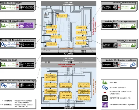
arbitrary tool types and sizes could be simulated and evaluated with the FBS. The UML class
diagram of the resulting software structure is presented in Figure 8.
Intuitive Graphical User Interface
The GUI of the FBS was developed following the structure of the simulation development
process. The FBS was divided into three GUI elements for general tasks, simulation
preparation and simulation evaluation. In the development phase, the main focus was laid on
simplified user interactions and user requirements in a functional and appealing environment.
After software initialization, the user is prompted to select a user path in the Main GUI of the
FBS, which was designed in the familiar Windows desktop environment (Figure 9).
Subsequently, the user is granted access to all but only the options, which are needed for the
preparation of a three-dimensional tapping simulation, while the implemented active help
supports the user of the FBS during all operations with simple and self-descriptive dialogs.
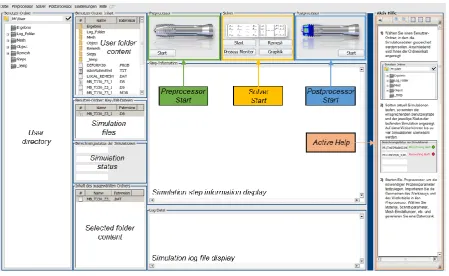
Fig. 9: Main GUI.
The Preprocessor GUI can be started after a valid user path has been selected or generated. It
is divided into several tabs for file input, parameter modification and execution of software
routines, next to a DirectX window for model visualization purposes, as well as an active
help section. Input data is converted into key-data in the declared script language using
according user interactions (Figure 10). As in all other GUI windows of the FBS, an active
help section is included in the Preprocessor to support the user during the simulation
preparation phase.
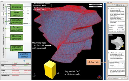
Fig. 10: Process steps in the Preprocessor GUI.
In the first tab (geometry), the 3D geometries of tool and workpiece models can be imported
and material properties can be defined, whereby the according subroutines are automatically
executed in the background. Amongst other parameters, the choice of a correct minimum
element edge length is an important criterion when meshing (second tab), to be able to reach
convergence during numerical calculation and is automatically calculated without further user
interactions. In the third tab (simulation parameters), the number and increment of simulation
steps are automatically determined considering rotational speed, minimum element edge
length and cutting speed. Additional parameters like the heat transport coefficient and
suitable parameters of friction define the interactive relationship of the objects workpiece and
tool. In the fourth tab, process parameters are defined. Using the input of the rotational speed
and pitch, the feed speed is calculated automatically. Tool rotation is defined about the z-axis.
Since a congruent axis is defined for the tool and workpiece models, the tool positioning as
well as the determination of the center of rotation can be carried out accordingly.
whereby the described subroutine is executed. After the tool model is automatically
positioned in z-direction, the user is able to initialize a rotation of the tool around the z-axis
as required, so that the teeth of the tapping tool are in the correct engagement situation, while
these positioning movements are traceable through the visualization window. Using controls
of the last tab (data generation), all input data will be converted and stored in a DEFORM
database. A function control implemented in the Preprocessor GUI verifies, that all input data
is continuously sent to DEFORM and validates plausibility of sent and received data.
Therefore, an additional response code for communication with the FEM-based software
system has been programmed for all the tabs included in the Preprocessor. Using this
response code, value limits are checked after data generation, so that the updated information
can be evaluated for its accuracy.
Subsequently, the simulation calculation can be started via the according Solver Control,
which is accessible from the Main GUI. The calculation is executed in the background using
the DEFORM solver module, while the simulation status, as well as a simulation log file is
continuously displayed in the Main GUI for monitoring purposes. Should the calculation be
interrupted due to a mesh convergence error, the user is notified and can start a manual
remesh procedure through the function implemented within the Solver Control, whereby the
remesh routine is executed according to the mesh grid generation.
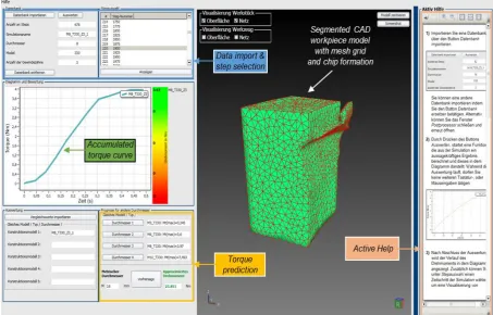
An intuitive evaluation of the calculated simulation is possible in the Postprocessor GUI
(Figure 11), since the user is able to import the simulation database of any finished tapping
simulation.
Due to the workpiece segmentation, the tapping tool does not remain in constant contact to
the workpiece during the simulation, resulting in a torque curve consisting of incoherent
peaks. To accumulate the torque peaks into an evaluable torque course, the according
validated mathematical functions were adapted and included in the FBS (Oezkaya and
(1)
Hereby, t corresponds to the simulation time, i represents the number of torque peaks, ti is the
time of the according torque peak and M is the torque value. The torque accumulation is
automatically carried out in the background, without any required user input and the resulting
torque curve is then displayed as a graph in a diagram side by side to results of further
simulations, enabling the user to easily evaluate and rank the tapping tool performance and
consider possible improvements.
Furthermore, a torque prediction method was implemented in the Postprocessor, so that the
user is able to predict maximum torque values for further diameters, as soon as four
simulations of the same tapping tool type with varying diameters have been carried out.
Therefore, a parabolic dependency between the metrical tool diameter and the resulting
maximal torque value could be used, to extrapolate a torque value out of four simulation
results of the same tool type, which was proposed and validated in (Oezkaya and Biermann,
2018). With this function, the user of the FBS could choose any metrical diameter dpred up to
the geometrical transmission limit g, at which the tapping tool starts to consist out of ω = 4
flutes instead of ω = 3, and obtain an according predicted relative torque value predMmax,
without having to perform an entire simulation routine for the desired diameter.
(2)
The parabolic regression curve Mpar is dependent on the set of the already simulated and
available torque curves setMaval, whereby four simulation results, which were previously
accumulated with equation 1, are considered:
(3)
(4)
To acquire the parabolic regression curve, the available evaluated torque maxima were sorted
by the size of metrical tool diameter, whereby all of the described processing steps were
automated, concluding in a further simplified and user-friendly software structure.
(5)
Next to the numerical evaluation procedures, a three-dimensional graphical visualization of
the tapping simulation was implemented within the GUI of the Postprocessor to further
illustrate the process conditions, workpiece deformation, chip formation and tool position.
Thereby, the user could choose to display any desired simulation step included in the chosen
simulation database. The chosen simulation step and the according model geometries and
Simplified simulation model generation and evaluation procedures
To provide an overview of the resulting simplified simulation model generation and
evaluation, the example of a helical fluted M8 tapping tool is used. As described above,
several necessary simulation parameters, including the chip thickness, minimal mesh element
size, simulation step amount and heat transfer coefficients are automatically provided by the
FBS, so that minimal user interactions and no in-depth knowledge of FEM simulation are
required to prepare the tapping simulation. The simulation parameters for the
three-dimensional M8 tapping simulation are listed in Table 1, whereby parameters that are
provided by the FBS are highlighted in green.
Table 1: Simulation parameters and tapping tool and workpiece properties.
Tapping tool properties Workpiece properties
Tool diameter M8 (d = 8 mm) Core hole diameter d
1 = 6.8 mm
Tool type Uncoated helical flute tap Outer diameter d
2 = d + 0.5mm = 8.5 mm
Tooth pitch P = 1.25 mm Height P + 0.25 mm = 1.5 mm
Chamfer length LC = 3 x P = 3.75 mm Chip thickness = 0.1078 mm
Chamfer angle ß = 15° Heat transfer coefficient hc = 45 W/m
2
∙K
Number of flutes = 3 Threading depth 3.75 mm
Cutting speed vc = 12 m/min
Rotational speed n = 477 1/min
Feed speed vf= 9.9375 mm/s
Material model Johnson and Cook material model
Material cemented carbide Material AISI-1045
Mesh elements 200,000 Mesh elements 60,000
Maximal mesh
element size 0.07189 mm
Minimal mesh
element size = 0.03595 mm
Object type Rigid Object type Plastic
In contrast to conventional simulation model generation, the user only has to specify the
geometrical tapping tool properties, the cutting speed vc and choose materials for tool and
workpiece, whereas all other necessary parameters including material parameters are
automatically defined by the FBS. Additionally, all required user inputs are elaborated in the
Active Help of the Preprocessor, concluding in a decreased simulation model generation
effort by more than 50 % compared to the complex GUI of DEFORM.
After successful numerical calculations, a simple evaluation of the simulation results is
possible in the Postprocessor, whereby the occurring torque over time is depicted in the
diagram without further user interactions, which would be necessary within DEFORM. The
torque is the most relevant process parameter for the evaluation of the tapping process, so that
Figure 11 for the M8 tapping tool simulation. The occurring maximal torque values are
automatically included within the corresponding colored scale, so that the conventionally
time-consuming simulation evaluation procedures could be strongly simplified through the
developed FBS, without compromising their significance. In this context, it should again be
mentioned that execution of all methods described in this chapter would not have been
possible without previously establishing external control over DEFORM.
The numerical results of the introduced simulation of the uncoated M8 tapping tool with
helical flutes are not essential for the CA-Channel and software development methods
described in this research paper, but included for the sake of completeness. The segmented
torque course, which is automatically accumulated with the FBS Postprocessor is depicted
and compared to according experimental investigations in Figure 12. Since the simulated
tapping depth corresponded to the tool’s chamfer length, the chamfer length also considered
in the experimental study. The numerically determined torque course, which was
accumulated in accordance to equation 1, shows good agreement to the experimental results,
confirming the quality of the segmented simulation model.
With the results of three further simulations using the same tapping tool type with the
diameters M3, M6 and M10, an extrapolation curve could automatically be generated.
Afterwards, torque values for various other tool diameters could be determined, which is
exemplary illustrated for the diameters M12, M14 and M16 and in conclusion compared to
experimental and simulative values, showing overall good agreement. The relatively large
deviation between 17.15 Nm (experimental) and 20.08 Nm (predicted) can be traced back to
the model simplification procedures. Nevertheless, the predicted torque values could be used
by too manufacturers to evaluate the tool performance tendency associated with the
modification of design parameters. Further experimental and simulative studies were carried
out in previous investigations (Oezkaya and Biermann, 2017; Oezkaya and Biermann, 2018)
and are not included here, since the focus of this paper lies on the developed software system,
Fig. 12: Evaluation of numerically calculated values.
CONCLUSIONS
In this paper, a developed FEM-based software system for the intuitive modelling of
three-dimensional tapping tool simulations is presented. In this context, the commercial FEM
software DEFORM was externally controlled for the first time, although a typical application
programming interface does not exist. Therefore, several software routines and algorithms
were developed to decouple the necessary features from the DEFORM user interface and to
implement these within a newly designed user environment. In addition, a three-dimensional
graphical visualization of tool and workpiece models, as well as mesh grids, positioning and
chip formation were included within the developed Preprocessor and Postprocessor.
Using the FBS, a tool design engineer could simulate the manufacturing process using
parameters and comparing simulation results, a fast method to deduce optimal tool design
parameters is provided, before tool prototypes are fabricated, so that many experimental field
tests, resources and development time could be saved. The extensive amount of experience
required for the preparation and execution of FEM simulations could be minimized by
automating multiple parameter calculations and simplifying user interactions in an adequate
style.
The here presented FBS is a novel research effort and represents first approaches, which
increase the understanding of the tapping process and move forward the 3D modelling and
simulation of complex manufacturing processes. It could be concluded that the external
control of DEFORM is achievable, so that novel possibilities of creating software solutions to
simplify the simulation model development, or automate extensive simulative studies based
on DEFORM, exist. These possibilities should be exploited in future studies, since they
present a high potential concerning a better process understanding and the implementation of
FEM analysis in further areas of engineering without in-depth knowledge of simulative
procedures.
ACKNOWLEDGMENTS
The Institute of Machining Technology would like to give thanks for the industrial research
cooperation and collaboration with the company Schumacher Precision Tools GmbH in
Remscheid, Germany. This work was supported by the Bundesministerium für Wirtschaft
und Energie (BMWi) [KF2198122KM3].
REFERENCES
1. Ahn J H, Lee D J, Kim SH, Kim H Y, Cho K K, "Effects of Synchronizing Errors on
Cutting Performance in the Ultra-High-Speed Tapping", CIRP Annals – Manufacturing
Technology, 2003; 52(1): 53-56.
2. Armarego E J A, Chen MNP, "Predictive Cutting Models for the Forces and Torque in
Machine Tapping with Straight Flute Taps", CIRP Annals – Manufacturing Technology,
2002; 51(1): 75-78.
3. Armarego E J A, "A generic mechanics of cutting approach to predictive technological
4. Cao T, Sutherland J W, "Investigation of thread tapping load characteristics through
mechanistics modeling and experimentation", International Journal of Machine Tools and
Manufacture, 2002; 42(14): 1527-1538.
5. Chen N M, Smith A J R, "Modelling of straight-flute machine tapping", Proceedings of
the Institution of Mechanical Engineers, Part B: Journal of Engineering Manufacture,
2011; 225(9): 1552-1567.
6. Constantin C, Croitoru S M, Constantin G, Bisu C F, "3D FEM Analysis of Cutting
Processes", Proceeding VIS '10 Proceedings of the 3rd WSEAS international conference
on Visualization, 2010.
7. Dogra A P S, DeVor R E, Kapoor S G, "Analysis of Feed Errors in Tapping by Contact
Stress Model", Journal of Manufacturing Science Engineering, 2002a; 124(2): 248-257.
8. Dogra A P S, Kapoor S G, DeVor R E, "Mechanistic Model for Tapping Process With
Emphasis on Process Faults and Hole Geometry", Journal of Manufacturing Science
Engineering, 2002b; 124: 18-25.
9. Dürr H, "Systematik der Ausführungsformen von Gewindebohrern mit spitzen Zähnen im
Anschneidteil und ihre Schneidgeometrie", Werkstatt & Betrieb, 1962; 95: 701-705.
10.Gardner J D, Dornfeld D, "Finite Element Modeling of Drilling Using DEFORM",
Laboratory for Manufacturing and Sustainability, 2006.
11.Gardner J D, Vijayaraghavan A, Dornfeld D A, "Comparative Study of Finite Element
Simulation Software", Laboratory for Manufacturing and Sustainability, 2005.
12.Hartkamp H G, "Erhöhte Schnittgeschwindigkeiten beim Bohren von Innengewinden",
Maschinen Markt, 1977; 83: 812-815.
13.Hartkamp H G, "Vorgänge an Werkzeugschneiden beim Innengewindebohren",
Maschinen Markt, 1978; 84: 826-829.
14.Kahles J F, "Machining Data Requirements for Advanced Machining Systems", Annals
of CIRP, 1987; 36: 523-529.
15.Körsmeier K, Technologie des Gewindebohrens: Das System Werkzeug – Spannzeug –
Leiteinrichtung, Technischer Verlag Resch KG, Gräfeling b. München, 1974.
16.Lorenz G, "On Tapping Torque and Tap Geometry", CIRP Annals – Manufacturing
Technology, 1980; 29(1): 1-4.
17.Mezentsev O A, DeVor R E, Kapoor S G, "Prediction of Thread Quality by Detection and
Estimation of Tapping Faults", Journal of Manufacturing Science and Engineering,
18.Mezentsev O A, Zhu R, DeVor R E, Kapoor SG, Kline WA, "Use of radial forces for
fault detection in tapping", International Journal of Machine Tools and Manufacture,
2002b; 42(4): 479-488.
19.Mota P R, Reis A M, Machado A R, Ezugwu E O, Da Silva M B, "Tool wear when
tapping operation of compacted graphite iron", Proceedings of the Institution of
Mechanical Engineers, Part B: Journal of Engineering Manufacture, 2013; 227(11):
1704-1713.
20.Oezkaya E, Biermann D, "Segmented and mathematical model for 3D FEM tapping
simulation to predict the relative torque before tool production", International Journal of
Mechanical Sciences, 2017; 128-129: 695-708.
21.Oezkaya E, Biermann D, "Development of a geometrical torque prediction method
(GTPM) to automatically determine the relative torque for different tapping tools and
diameters", International Journal of Advanced Manufacturing Technology, 2018; 62(1-4):
1465-1479.
22.Oezkaya E, FEM-basiertes Softwaresystem für die effiziente 3D-Gewindebohrsimulation
und Werkzeugoptimierung mittels CFD-Simulation, Vulkan Verlag, 2016.
23.Oezel T., "Computational modelling of 3D turning: Influence of edge micro-geometry on
forces, stresses, friction and tool wear in PcBN tooling", Journal of Materials Processing
Technology, 2009; 209(11): 5167-5177.
24.Pampel A, Untersuchung über Zerspanungs- und Abnutzungsvorgänge an
Mutterngewindebohrern, Dissertation, Sächsischen Technischen Hochschule zu Dresden,
1931.
25.Pietzsch L, "Entwicklung einer Werkzeugbestform für Gewindebohrer mit spitzen
Zähnen im Anschneidteil", Werkstatt & Betrieb, 1962; 95: 809-812.
26.Puzović R, Kokotović B, "Prediction of thrust force and torque in tapping operations
using computer simulation", FME Transactions, 2006; 34(1): 1-5.
27.Schallbroch H (1951), Bohrarbeit und Bohrmaschinen, Hanser-Verlag.
28.Schmidt W, Dürr H, Pietzsch L., "Ein neuartiges Gewindeschneidwerkzeug:
Untersuchungen und Entwicklungen an Gewindebohrern mit spitzen Zähnen im
Anschneidteil", Werkstatt & Betrieb, 1962; 95: 627–630.
31.Stoewer H J., "Schneidversuche mit Gewindebohrern auf Stahl", Stock-Zeitschrift, 1932;
31–42.
32.Tengyun C, Batzer S A, Sutherland J W., "Effects of Cutting Fluid Type on the
Dimensional Accuracy of Tapped Threads", Department of Mechanical
Engineering-Engineering Mechanics, 1999; 95–100.
![Fig. 4: Flow chart describing STL conversion [a)] and meshing procedure [b)].](https://thumb-us.123doks.com/thumbv2/123dok_us/8362214.1671850/10.595.77.525.77.297/fig-flow-chart-describing-stl-conversion-meshing-procedure.webp)
![Fig. 5: Exemplary material Key-File [a)] and parameter conversion procedure [b)].](https://thumb-us.123doks.com/thumbv2/123dok_us/8362214.1671850/11.595.76.525.153.343/fig-exemplary-material-key-file-parameter-conversion-procedure.webp)