www.astesj.com 51
Optimized Multi-focus Image Fusion Using Genetic Algorithm
Arti Khaparde*, Vaidehi Deshmukh
Department of Electronics and Telecommunication, Maharashtra Institute of Technology, Pune-411038, India
A R T I C L E I N F O A B S T R A C T
Article history:
Received: 06 December, 2016 Accepted: 13 January, 2017 Online: 28 January, 2017
Optical imaging systems or cameras have a convex lens with limited depth of field. So, multi-focus images are obtained when such systems are used to capture an image of a particular scene. These images are fused to get all-in-focus image. This paper proposes a new simpler method of multi-focus image fusion. Instead of decomposing input image into blocks in pyramid style, the proposed algorithm considers the complete image for edge detection. The proposed algorithm uses the genetic algorithm (GA) to find out the optimum weights from extracted edges and then fuses the images with the fusion rule based on optimized weights. Experimental results show that this superimposition method performs well; consumes less computation time and thus proves to be suitable for hardware implementation.
Keywords: Image fusion Superimposed Genetic algorithm
1. Introduction
Multi-view information of the scene is obtained from different images captured using different angles and variable focal length of the lens of a camera. In practice, all cameras consist of convex lens and have limited depth of a field. Hence while capturing an image using such camera; certain objects appear sharp whereas others appear blurred depending upon the distance from the lens. Thus multi-focus images with images different objects in focus are obtained [1].
For human perception or machine vision, a well-focused image is preferred. This image can be obtained in optical or computational way. Optical way is to reduce the lens aperture so as to increase the focal length of a lens. But this increases the diffraction and degrades the image resolution. Also small amount of light enters the camera and dark image is produced. De-convolution processwhen carried out on the image produces the sharp image in a computational way. But, this requires the knowledge of camera specifications and also results of this methodare affected by the presence of noise [2]. So, the way out is to combine two or more multi-focus images together.This is multi-focus image fusion.
A single composite image is constructed by integrating the in-focus portions of each image. Such fused images are also useful
in biomedical imaging, target identification, microscopic imaging, military operations, machine vision, and object recognition and so on.
A large number of image fusion algorithms have been invented so far. These methods work in spatial domain and transform domain.
Spatial domain methods mainly work upon the image blocks. Sharper image blocks from multi-focus images of the same scene are selected based upon the sharpness measure such as EOG (Energy of Gradient) [3] and spatial frequency [4] and sometimes using focus detection algorithm [5-9]. The main difficulty of these methods is to select the block of optimum size, on which the quality of fused image depends. Too small block gets affected by noise and causes incorrect selection. Too large block size causes sharp and blur pixels to get into the same block which leads to blocking artifacts. Hence the quality of the fused image degrades. In [10], authors have used genetic algorithm to optimize size of the block to obtain better fused image. Proposed fusion techniques apply edge features of an entire image to the genetic algorithm.
In transform based methods, images are decomposed into constituent low resolution images using scale and multi-resolution transforms, due to which computational complexity increases. To reduce this computational complexity, a hybrid fusion technique of DWT and GA is proposed in [11]. This
ASTESJ
ISSN: 2415-6698*Corresponding Author: Arti Khaparde, Dept. of E&TC, Maharashtra Institute of Technology, Pune, India, 411038, [email protected]
www.astesj.com
Special Issue on Computer Systems, Information Technology, Electrical and Electronics Engineering
method is used to fuse thermal and visual satellite images and outperforms others. Generally, transform based methods consist of three steps viz. decomposition, coefficients fusion and reconstruction. These methods use Laplacian pyramid [12], DCT [3], Wavelet, Curvelet [13], Shearlet [14] and contourlet [15] etc. transforms for decomposition of images. Multi-scale decomposition effectively extracts the visually important information of the images such as lines and details; but it produces halo artifacts near the edges. Hence final fused image has to be sharpened so that edges which are vital for the interpretation of the scene become clear. So, authors in [16, 17] suggest fusion methods which can preserve edges in the final fused image. Morphological toggle contrast operator [16] used to extract edge features which can be used for fusion; takes more time for feature extraction. Edge preserving method proposed in [17] uses decomposition based on weighted least squares filter for the fusion of multi-focus images using focus-measure based fusion rule. The method is fast and effective but the difficulty is to adaptively determine the number of decomposition levels in fusion process. In [18], a fusion method based on saliency detection is proposed. Initially, input images are decomposed into detail and approximation layers by using simple average filter. Then method constructs weight map depending upon focused regions detected using visual saliency. This method works faster in spite of decomposition and produces the fused image with better contrast.
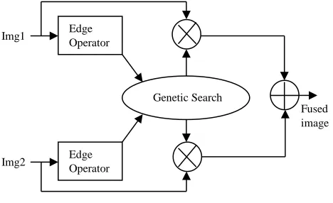
In view of above analysis, authors propose the algorithm which can reduce the computational complexity due to decomposition with simple but fast fusion rule. The proposed novel technique uses three steps to fuse an image
It finds the edges using which features are extracted.
These features are used to calculate optimum weights with the help of genetic algorithm.
And finally images are fused with these weights using the fusion rule of superimposition.
Two fusion techniques are proposed here. They are edge-superimposition, edge-GA-superimposition. This paper presents extended workoriginally presented in ICIS2016 [1].
The paper is organized as follows: Section II explains the proposed fusion techniques. Section III gives the objective evaluation parameters which are used to examine the performance of the proposed method. Section IV deals with the results and Section V is conclusion.
2. Proposed Fusion Techniques
2.1.Edge Superimposition
Quality of the image depends upon the focus and sharpness of objects present in the image. So sharper images have more information than the blurred ones. Sharper images are obtained using fusion; but fusion makes edges blur. Thus to achieve an improvement in the sharpness of the fused images, this algorithm superimposes the edges on the input images. Sobel and Canny operators are used for edge detection. The edges are then averaged to form a new edge image E. This image is superimposed on the first input using weighted addition method.
𝐼𝑚𝑎𝑔𝑒
3 =𝑘
1*𝐼𝑚𝑎𝑔𝑒
1 +𝑘
2∗ 𝐸
(1)𝑘
1=
𝐴𝑣𝑔 𝑝𝑖𝑥𝑒𝑙 𝑣𝑎𝑙𝑢𝑒 𝑖𝑛 𝐼𝑚𝑎𝑔𝑒1
𝑀𝑎𝑥 𝑝𝑖𝑥𝑒𝑙 𝑣𝑎𝑙𝑢𝑒 𝑖𝑛 𝐼𝑚𝑎𝑔𝑒1
(2) 𝑘2= (1 − 𝑘1)*0.1 (3)
The intermediate Image3 is superimposed on the second input image to form the final output image.
𝐹𝑖𝑛𝑎𝑙 = 𝑘3∗ 𝐼𝑚𝑎𝑔𝑒2+ 𝑘4∗ 𝐼𝑚𝑎𝑔𝑒3 (4)
𝑘
3= 1 − (
𝐴𝑣𝑒𝑟𝑎𝑔𝑒 𝑝𝑖𝑥𝑒𝑙 𝑣𝑎𝑙𝑢𝑒 𝑖𝑛 𝐼𝑚𝑎𝑔𝑒2
𝑀𝑎𝑥 𝑝𝑖𝑥𝑒𝑙 𝑣𝑎𝑙𝑢𝑒 𝑖𝑛 𝐼𝑚𝑎𝑔𝑒2
)
(5) 𝑘4=1 (6)
𝑘4 is taken to be unity as it is used for the intermediate image that
is already superimposed.
2.2 Edge-GA-superimposition
Input images are converted into edge images using edge operators. Statistical features in the form of normalized central moments up to order 3 are extracted from each edge image. Total 16 moments are selected. Mean and standard deviation of edges (along x and y directions in case of Sobel) are also calculated. Finally, the feature vector containing the moments, mean and standard deviation is formed and its size is 1 X 20.
The genetic search [1, 11] starts by generating a population of size 100. This population consists of randomly generated binary strings of length 10. Before evaluating the individuals, they are converted from binary to decimal equivalent such that every binary string lies in the range of 0 to 1.This conversion is given as:
Ll+ (Ul– Ll) * Decimal equivalent / (2n− 1) (7)
Where, Lower limit (Ll) =0, Upper limit (Ul) =1, n=Number of bits in the binary.The individuals are evaluated using mean squared error as the fitness function. Mathematically, this fitness function is given as:
𝐹𝐹 = {1
2( 1
d∑ [Fint(i) − Img1(i)] 2 d
i=1 ) + (
1
d∑ [Fint(i) − d
i=1
Img2(i)]2)} (8)
d is the dimension of the input vector which is 1 x 40. Fint(i) is
the intermediate fused image obtained by using the equation:
Fint(i) = Wint1∗ Img1+ Wint2∗ Img2 (9)
Img1 and Img2 are the input images, Wint1is the weight individual
being evaluated and:
Wint2= (1-Wint1) (10)
The value of the fitness function should be as small as possible. However, it can also be transformed to make the fitness function a maximization fitness using the function:
F(x) = 1/ (1 + FF) (11)
wheel selection, Rank based selection, and Tournament selection etc. [1, 11]. Here tournament based selection method with a tournament size of 2 is used. Crossover and mutation operations with probability 0.7 and 0.002 respectively are performed on the selected individuals in the next step. Uniform crossover and bit-flip mutation is used. These modified individuals replace the existing population. The process is repeated for 25 generations. It is experimentally observed that this search is converging in 20-23 generations. After the last generation, the optimum candidate is selected; which serves as first weightW1.The second weight is
obtained W2=1 − W1. (12)
On obtaining the two weights, each is assigned to the input images. Final fused image is obtained as a result of the addition of these optimally weighted images as:
Ffinal= W1∗ Img1+ W2∗ Img2 (13)
The block diagram for the process is described in Figure 1:
Fig. 1 Flow Diagram for Proposed method
3. Evaluation of the fused images:
The basic requirement is that the output images should contain all the valid and useful information present in the source images without introducing any form of distortion. This can be verified by comparing the resultant images visually, but, these methods, though very powerful, are subjective in nature. Hence, objective statistical parameters are usedfor the evaluation of fused images[15,19-24]. These parameters are defined as below.
3.1 Root Mean Squared Error:
RMSE = √1
mn[∑ ∑ Img1(i, j) − Img2(i, j)]
j−1 j=0 m−1 i=0
2 2
(14)
m, n: size of the input images 𝐼𝑚𝑔1 and 𝐼𝑚𝑔2
3.2 Peak Signal to Noise Ratio:
Peak signal to noise ratio gives the ratio of the maximum power of a signal and the power of corrupting noise.
PSNR = 20log10(
Max
√MSE) (15)
Max: Maximum possible pixel value, as 8 bits are used to represent a pixel, Max=255
3.3 Structural similarity index:
SSIM is used to model any image distortion as a combination of correlation losses, radiometric and contrast distortions. Higher the value of SSIM, more similar are the images. It can have a maximum possible value of 1. It is given by
SSIM(x, y) = (2μxμy+ c1)(2σxy+ c2)
(μx2+ μy2+ c1)(σx2+ σy2+ c2) (16)
Whereμx=average of x;μy= average of y; σx2= variance of x;
σy2=variance of y; σxy= covariance of x and y.
c1= (k1L)2,c2= (k2L)2 (17)
Where L = dynamic range of the pixel-values; k1= 0.01and
k2= 0.03 by default.
3.4 Entropy:
Entropy is used to give the amount of information contained in an image. Mathematically it is given as:
E = − ∑L−1i=0Pilog2Pi (18)
Pi is the probability of occurrence of a pixel value in the image, L
is the number of intensity levels in the image. Increase in the value of entropy after fusion indicates that the information contained in the image has increased.
3.5 Mutual Information:
It is an indicator of the information obtained from the source images and the quantity that is conveyed by the fused image. MI = MIF,I1+ MIF,I2 (19)
MI F,I1 = ∑ PF,I1(f, i1) log2
PF,I1(f,i1)
PF(f) PI1(i1) (20)
MI F,I2 =∑ PF,I2(f, i2) log2
PF,I2(f,i2)
PF(f) PI1(i2) (21)
Where MIF,I1 denotes the mutual information between the fused
image and the first input image,MIF,I2 denotes the mutual
information between the second input and the fused image, PF,I1(f, i1) and PF,I2(f, i2) are the joint histograms of fused image,
input 1and fused image, input 2 respectively, PF(f), PI1(i1) and
PI1(i2) are the histograms of the fused image, input 1 and input 2
respectively.
3.6 Run Time:
It gives a measure of the time required to execute the algorithm in seconds.
3.7 Image Quality Index:
Mathematically [9], IQI = 4σxyx̅y̅
(σx2+σy2)[(x̅)2+(y̅)2] (22)
where x̅, y̅ are the means of x and y respectively, σxy is the
covariance of x and y, σx2, σy2 are the variances of x and y
respectively. Img1
Img2
Edge Operator
Edge Operator
Genetic Search
4. Experimental Results
4.1 Experimental settings
All algorithms are coded using Python and implemented on Intel dual core, i5, 3.14GHz processor. Edges of input images are extracted using Sobel and Canny operators in both the fusion techniques. DWT-GA which uses HARR Wavelets for the decomposition is implemented for the reference [1, 11]. These algorithms are tested on different types of images from a database as well as on real time images captured by a camera (canon 60D, Tamron-SP 90 Di VC-macro), focusing on different object in every image. Different evaluation parameters mentioned previously are used for analyasis of results.
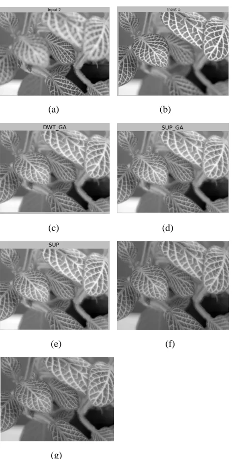
4.2 Results for database image sets
(a) (b)
(c) (d)
(e) (f)
(g)
Fig. 2 (a)-(b): Data base input images, (c)DWT_GA (d)SUP_SOB (e) SUP_CA,(f) SUP_GA,(g) CA_GA
4.3 Results
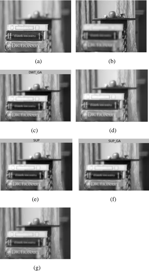
Quantitative evaluation for different methods is carried out. Table I and II compares results for different parameters for Database and real time images respectively. They represent the average value of the respective evaluation parameter when the proposed algorithm is applied to database images and 20 real time images. Fig. 2 and Fig. 3 show results for sample input images taken from database and real time image sets respectively. These results are obtained after applying the proposed method to these samples. It was observed that proposed methods give better results compared to those obtained by DWT_GA[11]. The analysis also shows that for database images Sobel operator gives better performance whereas for real time images Canny operator can be preferred.
TABLE I. COMPARISION OF RESULTS FOR DATABASE IMAGE SETS
Method
DWT_ GA
Edge-Superimposition
Edge-GA-Superimposition
Parameter
SUP_
SOB SUP_CA SOB-GA CA_GA
PSNR 34.409 34.066 34.865 34.409 34.086
SSIM 0.936 0.934 0.941 0.936 0.929
ENTROPY 7.359 7.371 7.361 7.359 7.314
MI 7.212 7.185 8.243 7.212 6.880
IQI 0.891 0.886 0.878 0.891 0.862
TIME(SEC) 0.242 0.008 0.007 0.229 0.773
TABLE II. COMPARISION OF RESULTS FOR REAL TIME IMAGE SETS
Method
DWT_ GA
Edge-Superimposition
Edge-GA-Superimposition
Parameter
SUP_ SOB
SUP_C A
SOB_ GA
CA_ GA
PSNR 21.076 20.768 21.365 21.076 21.805
SSIM 0.807 0.803 0.802 0.806 0.810
ENTROPY 7.337 7.262 7.401 7.336 7.446
MI 5.192 5.363 5.141 5.192 5.082
IQI 0.601 0.571 0.565 0.601 0.588
4.4 Results for real time image sets
(a) (b)
(c) (d)
(e) (f)
(g)
Figure 3: (a)-(b)Realtimeinput images, (c)DWT_GA, (d)SUP_SOB, (e)SUP_CA, (f)SUP_GA,(g) CA_GA
TABLE III: PERFORMANCE ANALYSIS OF PROPOSED EDGE BASED METHODS
Parameter Images
From Database Real time
PSNR SUP-CA CA-GA
SSIM SUP-CA CA-GA
ENTROPY SUP-SOB CA-GA
MI SUP-CA SUP-SOB
IQI SOB-GA SOB-GA
TIME SUP-CA SUP-CA
5. Conclusion
The follwing Table III gives us the consolidated perfomance of proposed techniques which work well with respect to DWT method. From above table it can be concluded that proposed edge based techniques work better than DWT based fusion techinque [11]. Edge GA based superimpostion method gives better performance for real time images as the weights are calculated and optimized using image statistics as compared to the constant values taken in edge superimposition method. The added advantage is its simplicity as decomposition and reconstruction of images is not required.As a result the method cosumes less run time compared to DWT based GA [11]. This property along with reduced computational complexity makes it simpler for hardware implementation and paralleling processing. Subjective analysis shows that the contrast of the images fused by the proposed method can be further improved. For real time images Canny based Genetic algorthm gives better performance but the computational time required is large. Thus, this algorithm can be further extended to fuse real time images in a quick and efficient manner which can be used in variety of applications.
References
[1] Arti Khaparde, Maitreyi Abhyankar and Vaidehi Deshmukh, “Spatial domain decision based image fusion”, 2016 IEEE/ACIS 15th International Conference on Computer and Information Science, ICIS 2016 – Proceedings, 23 August 2016, Article number 7550766; DOI: 10.1109/ICIS.2016.7550766.
[2] V. Aslantas, R. Kurban, “Fusion of multi-focus images using differential evolution algorithm”, Expert Systems with Applications vol.37, 2010, pp 8861–8870.
[3] Liu Cao; Longxu Jin; Hongjiang Tao; Guoning Li; ZhuangZhuang; Yanfu Zhang, “Multi-Focus Image Fusion Based on Spatial Frequency in Discrete Cosine Transform Domain”, IEEE Signal Processing Letters, Year: 2015, Volume: 22, Issue: 2, pp. 220- 224.
[4] Y. Zhang, et al., Multi-focus image fusion based on cartoon-texture image decomposition, Optik - Int. J. Light Electron Opt. (2015), http://dx.doi.org/10.1016/j.ijleo.2015.10.098
[5] Xiaoli Zhang, XiongfeiLi, ZhaojunLi, YuncongFeng, “Multi-focus image fusion using image-partition-based focus detection”, Signal Processing, vol.102, (2014), pp. 64–76
[6] Said Pertuz, Domenec Puig, Miguel Angel Garcia, Andrea Fusiello, “Generation of All-in-focus Images by Noise-robust Selective Fusion of Limited Depth-of-field Images”, IEEE Transactions on Image Processing, Year: 2013, Volume: 22, Issue: 3, Pages: 1242 – 1251.
[7] Baohua Zhang, Xiaoqi Lu, Haiquan Pei, He Liu, Ying Zhao and Wentao Zhou,“Multi-focus image fusion algorithm Based on focused region extraction”, Neurocomputing.
[8] X. Zhang, et al., “A new multifocus image fusion based on spectrum comparison”, Signal Processing 2016, http://dx.doi.org/10.1016/j.sigpro.2016.01.006i
[9] Jinsheng Xiao, Tingting Liu, Yongqin Zhang, Baiyu Zou, Junfeng Lei and Qingquan Li, “Multi-focus image fusion based on depth extraction with inhomogeneous diffusion equation”, Signal Processing,
[10] Veysel Aslantas, Rifat Kurban, “Extending depth-of-field by image fusion using multi-objective genetic algorithm”, 7th IEEE International Conference onIndustrial Informatics, 2009. INDIN 2009, pp. 331-336.
[11] Chaunté W. Lacewell, Mohamed Gebril, Ruben Buaba, Abdollah Homaifar, “Optimization of Image Fusion Using Genetic Algorithms and Discrete Wavelet Transform”, Radar Signal & Image Processing, IEEE, 2010 [12] Chuanzhu Liao, Yushu Liu, Mingyan Jiang, “Multi-focus image fusion using
Laplacian Pyramid and Gabor filters”, Applied Mechanics and Materials, vol. 373-375, 2013 , pp 530-535.
[14] G. Guorong; X. Luping; F. Dongzhu, “Multi-focus image fusion based on non-subsampled shearlet transform”, IET Image Processing, Year: 2013, Volume: 7, Issue: 6, pp: 633 – 639.
[15] Y.Yang; S.Tong; S.Huang; P.Lin,“Multifocus Image Fusion Based on NSC T and Focused Area Detection”, IEEE Sensors Journal, Year: 2015, Volume: 15, Issue: 5, pp. 2824 – 2838
[16] Xiangzhi Bai, Fugen Zhou, BindangXue, “Edge preserved image fusion based on multi-scale toggle contrast operator”, Image and Vision Computing, vol.29, 2011, pp 829–839.
[17] Yong Jiang, Minghui Wang, “Image Fusion using multi-scale edge-preserving decomposition based on weighted least squares filter”, IET image Processing, 2014, vol. 8, Issue 3, pp.183-190.
[18] Bavirisetti DP, Dhuli R, Multi-focus image fusion using multi-scale image decomposition and saliency detection, Ain Shams Eng J, 2016, http://dx.doi.org/10.1016/j.asej.2016.06.011
[19] Wei-We Wang, Peng-Lang Shui, Guo-Xiang Song,”Multifocus Image Fusion In Wavelet Domain”, Proceedings of the Second International Conference on Machine Learning and Cybernetics, November 2003. [20] Tanish Zaveri, Mukesh Zaveri,” A Novel Region based Image Fusion
Method using High-boost Filtering”, Proceedings of the 2009 IEEE International Conference on Systems, Man and Cybernetics, San Antonio, TX, USA, October 2009
[21] Hugo R. Albuquerque, Tsang Ing Ren, George D. C. Cavalcanti,”Image Fusion Combining Frequency Domain Techniques Based on Focus”, IEEE 24th International Conference on Tools with Artificial Intelligence, 2012. [22] Wencheng Wang, Faliang Chang, “A Multi-focus Image Fusion Method
Based on Laplacian Pyramid”, Journal Of Computers, Vol. 6, No. 12, December 2011, pp. 2559-2566
[23] Yifeng Niu, Lincheng Shen, Lizhen Wu and Yanlong Bu,” Optimizing the Number of Decomposition Levels for Wavelet-Based Multifocus Image Fusion”, Proceedings of the 8th World Congress on Intelligent Control and Automation, Jinan, China, July 2010
[24] Zhou Wang, Alan C. Bovik, “A Universal Image Quality Index”, IEEE Signal Processing Letters, March 2002.