R E S E A R C H
Open Access
Resource efficient connectivity restoration
algorithm for mobile sensor/actor networks
Muhammad Imran
1*, Mohamed Younis
2, Noman Haider
3and Mohamed A Alnuem
4Abstract
Maintaining inter-node connectivity is of a paramount concern in most applications of mobile sensor/actor networks because nodes have to report their data and coordinate their operations. Failure of a node may partition the inter-node network into disjoint segments, and may thus hinder data delivery and inter-node coordination. This article presents a novel resource efficient connectivity restoration algorithm (RECRA) that opts to repair severed connectivity while imposing minimal overhead on the nodes. To avoid overreacting to non-critical failure, RECRA identifies critical/non-critical nodes and only triggers the recovery when a critical node fails. The failure of a node is detected by its neighbors and a recovery procedure is executed based on their proximity, status (critical/non-critical), and transmission range. RECRA prefers to employ a non-critical node and moves it to the place of failed node in order to limit the impact on coverage, scope of the recovery, and strangle successive cascaded relocations. In case non-critical nodes in the neighborhood are not available, the neighbors restore connectivity by exploiting their partially utilized transmission power and repositioning closer to the failed node. RECRA is validated analytically and through extensive simulations. The simulation results confirm the effectiveness of RECRA for both dense and sparse network segments and its performance advantage over contemporary schemes found in the literature.
Keywords:Wireless sensor and actor networks, Fault tolerance, Connectivity restoration, Node relocation, Topology repair
1. Introduction
Recent advances in sensing, wireless technologies, and smart actuation capabilities have paved the way for the emergence of small-sized and battery-operated mobile sensor/actor devices. These devices may be employed within the wireless sensor networks (WSNs) [1] to ex-tend their capabilities. The mobile nodes vary from smart sensors such as Micabot [2] and Robomote [3] to quite capable actors such as iRobotW710 [4] and Aerial mapping helicopter [5] that can deliver a response to an event. Augmenting WSN with mobile sensors and actors has led to the emergence of mobile sensor networks (MSNs) [3,6] and wireless sensor and actor networks (WSANs) [7], respectively. The role of an actor (or set of actors) is application dependent and is determined based on the requirements, environment, and the capabilities of actors. For example, an actor can deactivate a
landmine, carry weapons, extinguish a fire, and rescue a trapped survivor. An articulation of a sample autono-mous WSAN environment is shown in Figure 1.
In both MSNs and WSANs, maintaining network con-nectivity is extremely important throughout the network lifetime in order to satisfy application-level require-ments. For example, effective and accurate monitoring of an area requires maximal presence of sensors to re-ceive data from neighbors and perform aggregation or fusion. Similarly, most applications of WSAN necessitate availability of actors to establish and maintain a con-nected inter-actor topology in order to coordinate with each other on an optimal response and to synchronize their operations. For example, in disaster management applications, sensors detect and report the presence of survivors in the vicinity to the designated actors. The actors equipped with necessary equipment receive sen-sors data, process it, and share it with peer actors to de-termine the most appropriate set of actors that will participate in the operation. This requires that actors * Correspondence:[email protected]
1
Deanship of e-Transactions and Communication, King Saud University, Riyadh, Saudi Arabia
Full list of author information is available at the end of the article
should be able to communicate with each other and per-form appropriate action.
Nonetheless, the harsh application environment that MSNs and WSANs operate in makes nodes (i.e., sensors and actors) susceptible to physical damage and compo-nent malfunction. Failure of a critical node partitions the inter-node network into disjoint segments and conse-quently hinders data delivery and inter-node interaction. In addition, a node failure may cause significant loss of coverage. Since MSNs and WSANs operate autono-mously in unattended setups, replacing the failed node is often infeasible and the recovery should be a self-healing and agile process that involves reconfiguring the inter-node topology in a distributed manner. Moreover, the resource constrained nature of MSNs and WSANs re-quire the connectivity restoration process to be light-weight in terms of the incurred overhead and to limit the impact on network coverage.
This article presents a novel resource efficient connect-ivity restoration algorithm (RECRA) for repairing a top-ology after the failure of a critical node that caused partitioning the network topology into disjoint segments. In order to avoid unnecessary recovery overhead, RECRA classifies nodes into critical or non-critical to the net-work connectivity based on localized information. The neighbors detect the failure of a node F and decide to participate in the recovery based on their status, proxim-ity, and how partially they currently utilize transmission power. To minimize the scope, impact, and overhead of recovery, RECRA prefers to employ non-critical nodes and moves them to the location ofF. In case of unavail-ability of non-critical nodes, the neighbors ofF collabora-tively participate by gradually increasing their partially utilized transmission power and repositioning closer to-wards F. This is to minimize and balance recovery
overhead on individual nodes. The performance of RECRA is validated analytically and through extensive simulations. Simulation results confirm the effectiveness and efficiency of the proposed scheme compared to pub-lished schemes. To the best of the authors’ knowledge, RECRA is the first reactive scheme that combines the use of non-critical nodes, node mobility, and partially utilized transmission power of nodes in the recovery process.
The rest of the article is organized as follows. The next section describes the system model and discusses the network partitioning problem. Section 3 summarizes the related work. The detail descriptions of the proposed RECRA algorithm, pseudocode, and analysis are pro-vided in Section 4. The validation results and perform-ance analysis of RECRA are presented in Section 5. Finally, Section 6 concludes the article.
2. System model and problem statement
RECRA is applicable to an MSN or a WSAN. The mo-bile nodes can be a part of a flat network topology, in case of MSN, or form a second tier in hierarchical net-work architecture, e.g., actors or aggregation and for-warding units. The nodes are randomly placed in an area of interest where they discover each other and form a connected network. In the case of WSANs, this is an inter-actor network, i.e., no sensor nodes are involved. The nodes are assumed to be able to move on-demand with a consistent speed to reach their destination. How-ever, this movement is assumed to be more costly than other operations such as computation and message transmission. The communication range rmaxof a node refers to the furthest Euclidean distance that its radio can reach. We assume that all nodes can dynamically ad-just the output power of their radio when transmitting. This is very realistic assumption as popularly used radio WSAN field
A
S S
S
S S
S
S
S S
S
S
S
S
S
S
S
S S
S S
A
A A
A
A A
Actor-Actor communication Sensor-Actor communication Actor node
A
Sensor node S
hardware such as CC1000 [8] and CC2420 [9] offer a register to specify the transmission power levels at run-time. Each node is assumed to maintain a list of its dir-ect neighbors.
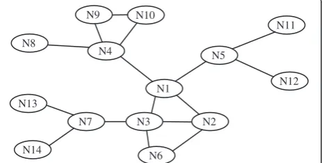
The effect of a node’s failure depends on the position of that node in the network topology. For example, the loss of a leaf node, such asN8 in Figure 2, has no nega-tive impact on the inter-node reachability. Meanwhile, the failure of a critical, i.e., cut-vertex node such as N1 partitions the network into disjoint segments. In order to tolerate the failure of a cut-vertex node, the existing schemes can be categorized into [10]: (i) proactive, (ii) reactive, and (iii) hybrid restoration. The proactive schemes provision fault tolerance by forming and main-taining a bi-connected topology. However, provisioning such a level of connectivity requires large node count, and thus boosts the cost and becomes impractical. On the other hand, in reactive schemes network responds only when a failure occurs. We argue that real-time res-toration better suits MSN and WSANs since they are asynchronous and reactive in nature and it is difficult to predict the location and the scope of the failure beforehand. Hybrid schemes identify critical nodes in advance and designate them backup nodes as part of their contingency plan. The distributed and dynamic nature of MSN and WSANs makes hybrid schemes very suitable for mission-critical time-sensitive applica-tions. RECRA falls in this category.
3. Related work
The issue of fault tolerance in context of MSNs and WSANs has also been studied in other contexts. For example, the fault-tolerant model presented in [11] designates multiple actors to each sensor and multiple sensors to each actor in order to guarantee event noti-fication even in case of either failure or inaccessibility. However, our fault-tolerant model is in context of maintaining inter-node connectivity rather than reliable event notification delivery. Some researchers have proposed topology control algorithms to provide fault tolerance. They used to construct a fault-tolerant
topology by adjusting the node transmission power. For example, two distributed heuristics were proposed in [12] for homogeneous mobile networks to maintain connected topology by controlling the output power of the radios. The idea is to adjust the transmission power of nodes according to topology changes. Similarly, two localized algorithms for heterogeneous wireless net-works were proposed in [13] to preserve a bi-connected network topology. Most of these schemes neither con-sider impact of node failure nor takes into account the limited communication range as bottleneck in maintain-ing connectivity.
Exploiting node mobility as a means of performance optimization has been pursued by multiple researchers both in the context of MSNs and WSANs. Energy con-servation, increased connectivity and coverage, mini-mized latency and asset protection are the contemporary metrics targeted by the node repositioning. The reader is referred to [14] for a survey. Meanwhile, employing node mobility to repair damaged network topologies has only recently started to attract attention. The work can be categorized into block and cascaded movement. Block movement often requires a high pre-failure connectivity in order for the nodes to coordinate their response. An example of block movement-based approaches is the work of Basu and Redi [15], where the network is assumed to be 2-connected prior to the failure and the goal is to maintain such connectivity even under link or node failure. Their approach is centralized that may not be suitable for distributed and dynamic nature of MSANs. A distributed approach to tackle the same problem was presented in [16]. Unlike [15,16], the ob-jective of this study is to maintain 1-connectivity. In the absence of higher level of connectivity, block movement is infeasible and nodes have to move in an independent manner, i.e., cascaded movement [6].
Approaches pursuing cascaded motion can be further categorized based on the network state that the individ-ual nodes are assumed to maintain. Some approaches like DARA [17] and LDMR [18] base the node participa-tion on having a list of 2-hop neighbors. DARA replaces the failed node“F”with one of its neighbor picked based on the node degree, distance, and ID, respectively. Repo-sitioning the neighbor causes more links to break and the relocation process repeats in a cascaded manner. In LDMR, the neighbors move toward“F”and get replaced by nearest non-cut vertices. Basically, each neighbor broadcast a message looking for the best candidate that replaces it. On the other hand, some approaches such as RIM [19], VCR [20], and C3R [21] avoid the increased overhead for tracking 2-hop neighbors and require each node to be aware only of their 1-hop neighbors. The proposed RECRA algorithm fits in this category as well. RIM relocates the neighbors of “F” (irrespective of N7
whether the failed node and neighbors are critical/ non-critical) inward until they become connected. Mov-ing critical nodes inward requires children to follow and hence the scope of recovery may spread across the network. Albeit RIM balances the load and is suitable for sparse networks; however, its performance worsens significantly in dense networks. In addition, shrinking the topology inward causes significant loss of coverage.
Unlike RIM, the neighbors in VCR [20] volunteer by moving towardsFwhile increasing their partially utilized transmission range until becomes connected. VCR ap-plies a limited-scale diffusion in order to strangle reper-cussions of increased transmission power and improve coverage. However, VCR does not assess the impact of a node failure on connectivity and may engage critical nodes in recovery. Moreover, the diffusion in VCR is quite costly in terms of movement overhead especially in dense networks. Unlike RIM and VCR, RECRA iden-tifies critical/non-critical nodes in advance and only trig-gers recovery in case of critical node failure. Moreover, RECRA prefers to employ non-critical nodes in recovery. Furthermore, it exploits the fact that some neighbors of
“F” are not using their full communication range and would thus be able to reach more distant nodes than
“F”. Consequently, RECRA employs fewer nodes and minimizes relocation overhead by exploiting their par-tially utilized transmission range.
A number of schemes cared for both connectivity and coverage. For example, C3R employs node relocation in order to cope with the loss of coverage and connectivity when a node fails [21]. Instead of reconfiguring the net-work topology, neighbors move back and forth to re-place the failed node in order to provide intermittent rather than permanent recovery. Obviously, this solution leads to frequent topology changes, imposes lots of over-head, and would thus become suitable as a temporary solution until spare actors are deployed. On the other hand, Akkaya and Janapala [22] address inter-actor con-nectivity and coverage at network setup time. Actors apply repelling forces to spread out and switch to attrac-tion force when the actors become disconnected. How-ever, they do not deal with actor failure.
4. Resource efficient connectivity restoration
After deployment, RECRA identifies critical/non-critical nodes in the network based on the localized information and neighbors monitor each other through heartbeats. The neighbors of a node F detect its failure through missing heartbeats and initiate a recovery process based on their status, proximity, and partially utilized trans-mission power. If there is a non-critical node, it will move to the position of Fand announces the success of recovery. Otherwise, some of the critical neighbors pur-sue recovery by moving inward while increasing their
transmission power until becoming connected. RECRA is described in detail in the balance of this section.
4.1. Identifying critical nodes
As mentioned earlier, the failure of a critical node par-titions the network into disjoint segments while the network stays strongly connected despite the loss of a non-critical node. Thus, it is imperative to assess the im-pact of a node failure on network connectivity in order to avoid unnecessary recovery overhead. In addition, in-volving critical nodes in the recovery process triggers cascaded node relocation and widens the scope of the recovery [10] which ultimately affect coverage. RECRA identifies critical/non-critical nodes in-advance in order to justify the need and minimize the overhead for toler-ating a node failure. A number of algorithms have been proposed in the literature to determine cut-vertices in a graph. These algorithms can be categorized into centra-lized and distributed. In centracentra-lized algorithms [23,24], each node is required to maintain information about the entire topology which involves very high communication overhead, and thus may not be suitable for large-scale dynamic networks.
On the other hand, distributed and highly localized algorithms are more appropriate for large-scale MSNs and WSANs to support high mobility, scalability, robust-ness, and resource optimization. Localized algorithms can quickly determine critical/non-critical nodes with far less communication overhead as they only process localized information. This is extremely desirable in dy-namic networks. However, these algorithms may classify some nodes as critical while they are not indeed critical in a network-wide view. With limited information, this is unavoidable because it is almost impossible for a node to know the alternate paths across the network. How-ever, the accuracy of determining non-critical nodes is 100%. Considering the potential advantages of localized algorithms and the fact that RECRA prefers to engage non-critical nodes in recovery, such a category of approaches fits well and the reduced accuracy is not a major concern. Therefore, RECRA employs a localized cut-vertex detection procedure of [25] that only requires 1-hop position information and executes on each node in a distributed manner.
network. Figure 3 shows an example topology. Nodes N2 throughN5 are neighbors ofN1 as can be observed. Node N1 is critical because its neighbors become dis-connected without it. Meanwhile, nodeN2 is intermedi-ate non-critical because its neighbors N1, N3, and N6 are connected without involving N2. Moreover, leaf nodes such asN8 are determined as non-critical, as their failure does not affect inter-node connectivity.
One may argue about the cost and implication of de-termining critical/non-critical nodes in RECRA. Each node in RECRA determines itself whether it is critical or not based on the localized information. This only involves computation overhead that is not a major con-cern compared to communication and movement over-head. Moreover, the distributed nature of RECRA equally divides this overhead on all nodes. Nevertheless, RECRA strives to minimize this computation overhead by executing this procedure only when a node or its neighbor changes its position. Second, the procedure is localized; therefore, it does not involve heavy computa-tions. Distinguishing critical/non-critical nodes allows RECRA to avoid overreacting against non-critical node failures and preferably engage non-critical nodes in re-covery which helps in minimizing rere-covery overhead.
4.2. Monitoring and failure detection
As part of their normal network operation, nodes peri-odically exchange heartbeat messages with their neigh-bors to update their status. The idea is based on monitoring vital signs of a body to determine the health condition. Similarly, nodes periodically update their status containing their ID, location, and criticality (i.e., critical/non-critical) to neighbors through heartbeat mes-sages. The periodicity of heartbeat messages depends on many factors such as the mobility of nodes, the nature of the application, and the environment in which the net-work serves in. Missing a number of successive heart-beats from a nodeFis interpreted as an indication of its failure by the immediate neighbors. This number is based on the duty cycle for the data collection process and based on the susceptibility of nodes to failure. Therefore,
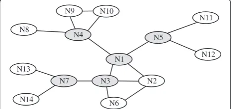
application designers are expected to assess these factors and determine the frequency and number accordingly. If the failed nodeFis non-critical there is no need to initi-ate any recovery as the network stays connected. On the other hand, if the failed nodeFis critical, the neighbors ofFwill apply RECRA and determine whether they will volunteer to participate in recovery or not based on the criteria described in the following section. Figure 4a shows that the failure of Node N1 divides the network into partitions and is detected by the neighbors.
4.3. Connectivity restoration
Upon detecting the failure of a critical node “F”, the neighbors initiate a recovery process. The scope of re-covery mainly depends on the position ofFand the sta-tus of the neighbors. In high-density networks, the probability of having non-critical nodes (intermediate and leaf ) is more and moving these nodes will have min-imal effect on inter-node connectivity and coverage. Therefore, RECRA prefers to exploit such an opportun-ity in the following manner:
If there is a non-critical node in the neighborhood, it will move to the location ofFand update its status to new neighbors, i.e., neighbors ofF. Since the absence of a non-critical node (intermediate and leaf ) does not inflict inter-actor connectivity, moving such a node to the place ofFrestores connectivity to the pre-failure level and does not require any further movement. Moreover, moving an intermediate non-critical node will almost preserve coverage loss as these nodes do have overlapped coverage with neighbors. Figure4b shows that the non-critical nodeN2 moves to the location of the failed node and determines that it becomes critical at the new location. It updates its new status to neighbors to be ready for any future-related failure. Such an updated message also serves as a confirmation of the success in restoring connectivity.
It might be possible that there is more than one non-critical node in the neighborhood ofF. This situation is bit complicated especially when the nodes are unable to coordinate. If the non-critical nodes are neighbors, they can coordinate and with the node that has the highest node degree and is the closest toFreplacingF. Repositioning such a node not only restores the connectivity, but also improves the coverage as shown in [10]. On the other hand, if non-critical nodes are unable to coordinate the recovery, they start moving towardsF. The first one to reachFupdates its status so that the remaining non-critical nodes stop and move back to their original location.
After failure detection, the critical neighbors ofFwait for the non-critical neighbors to establish connectivity for a pre-defined period of time, i.e., the time it takes for a node to travel a distance rmax. If the recovery message is received then the critical nodes are not required to participate in recovery. However, when the node density is low and connectivity is weak, the availability of imme-diate non-critical nodes in the neighborhood of F may be infrequent especially in the interior part of the net-work. Recovery in these situations is quite challenging and requires careful planning because moving a critical node indiscriminately may trigger a series of successive cascaded relocations that may prevail across the net-work. Such relocations impose high recovery overhead on individual nodes. Therefore, RECRA carefully orches-trates the recovery and collectively engages critical neighbors ofFthat meets the following criteria:
a. Participation criteria:
The critical neighbors of F perform their self-assessment in order to decide their role in recovery. This is based on their vicinity and how partially they utilized their transmission power.
i.Proximity. A critical nodeA∈neighbors (F) calculates
its distanced(A,F) toF. Ifd(A,F) is more than a percentageαof its ranger, node“A”is not required to participate in the recovery at this time, i.e., it stays as passive participant (PP). In other words, close
neighbors toFare favored as active participants (APs) because a slight inward movement of neighbors around Fcollectively occupies the uncovered spot. Assuming uniform distribution ofNnodes in a square area (L×L), the distance between two nodes in the same row is L:pffiffiffiffiffiffiffi2N and the distance between two diagonally neighboring nodes is L:pffiffiffiffiffiffiffi2N. Therefore,
the initial value ofαis set as the average proximity to neighbors:
a¼:5 Lffiffiffiffi
N
p þL:pffiffiffiffiffiffiffiffiffi2=N
It is worth noting that α is increased if node A is not connected within a preset time in order to recruit participants in the recovery. In other words, a PP can switch to AP depending on the progress in restoring restoration.
ii.Legibility factor (LF). The transmission power of
nodes significantly affects the network connectivity. While power level at the transmitter determines the reachable range, i.e., how far the receiver can be, high power may increase interference and boost the number of exposed nodes [26] in dense networks. Therefore, power control is usually pursued in order to balance the interest in high connectivity and efficient utilization of the wireless channel. Particularly, nodes carefully set their transmission power to achieve signal-to-noise ratio that suits the intended receiver and limits the potential of medium access collision with other nodes in the vicinity. Moreover, power control is further employed in order to conserve energy. RECRA exploits the fact that many nodes are not utilizing their full range and would be able to boost their transmission power to reach further receiver than their neighbors. Thus, nodes whose range is partially utilized should be favored in the recovery process. The LF of a node captures the effect of the ratio of current rangercto maximum rangermax, i.e.,
LF¼1ðrc=rmaxÞ;
N7 N4
N11
N6 N2
N5
N1
N3 N8
N10
N12 N9
N14 N13
N7 N4
N11
N6 N2
N5
N3 N8
N10
N12 N9
N14 N13
(a)
(b)
Nodes with high LF are favored. A node will decide to become AP if its LF exceeds a preset threshold β. Initially, β can be approximated based on the node density. Assume the size of the deployment region is
“Area”. For a uniform node deployment, the value of rc for establishing a connected network should be set such that
Area¼N:π14r2c;
where N is the number of nodes. Using this equation, rc¼
ffiffiffiffiffiffiffiffiffiffiffiffiffiffiffiffiffiffiffiffiffiffiffi
4:Area=Nπ
p
; which can be used to calculate an initial value ofβ. The initialβvalue is gradually decreased if no recovery is achieved within certain duration in order to increase the number of APs and restore connectivity.
b. Connectivity restoration
The APs exploit their partially unutilized transmission range and move towardsFuntil they reach others. Con-nectivity restoration involves the following steps:
i. Node relocation. The fact that a node is using a
fraction of its maximum communication rangermax
indicates that this node can move away from its current spot and makes up for the increased proximity to its neighbors by boosting the output power of its radio. An AP node“P”would exploit this capability by moving to a distanceγrmaxfrom
F. Prior to departing its current position node“P”
will notify its children. While moving, node“P”will increase its transmission power to stay connected to its children. Ifd(P,F) exceeds (rmax–rc), the children that are neither AP nor PP will follow to sustain their links toP, a step that referred in the literature as cascaded relocation [6]. RECRA opts to avoid or at least limits the scope of the cascaded relocation by favoring nodes that are close toFand
can grow their transmission power. At the start of the recovery processγis set to 0.5. The rationale is that if all neighbors ofFare at a distance ½rmaxaway fromF, the network becomes connected again [19].
ii.Connecting PP nodes.The PP nodes will wait for APs
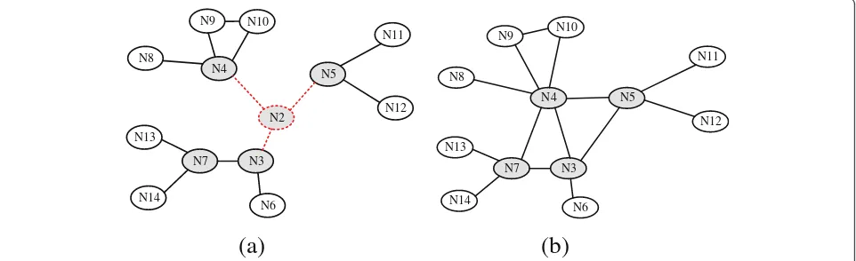
to re-establish connectivity. The rationale is that APs will end up in the vicinity ofF, yet not at the position ofF. Therefore, there is a high probability for PP nodes to be able to reach one of those APs without a need to incur overhead. If a preset time passes without hearing from an AP, a PP will increase the value ofαand/or and lowersβto become an AP. However, in this case an AP node will try to increase their transmission range first in order to find out whether other APs can be reached, before pursuing repositioning. When a PP becomes connected to an AP, it declares the success of the recovery (based on Theorem 1). For example, Figure5a provides an illustration where the critical neighbors ofN2 perform self-assessment based on the criteria prescribed earlier since there is non-critical neighbor to replaceN2. NodesN4 andN5 decide to become APs and move towardsN2 while increasing their transmission power until establishing a link to PP, namelyN3. Figure5b shows that the recovery process not only connects the neighbors ofN2, but also establishes some new links toN4 andN7. In addition,N4 andN5 maintain connectivity with their children, i.e.,N8,N9,N10, andN11,N12,
respectively. The children only adjust their transmission power to stay connected to their parents.
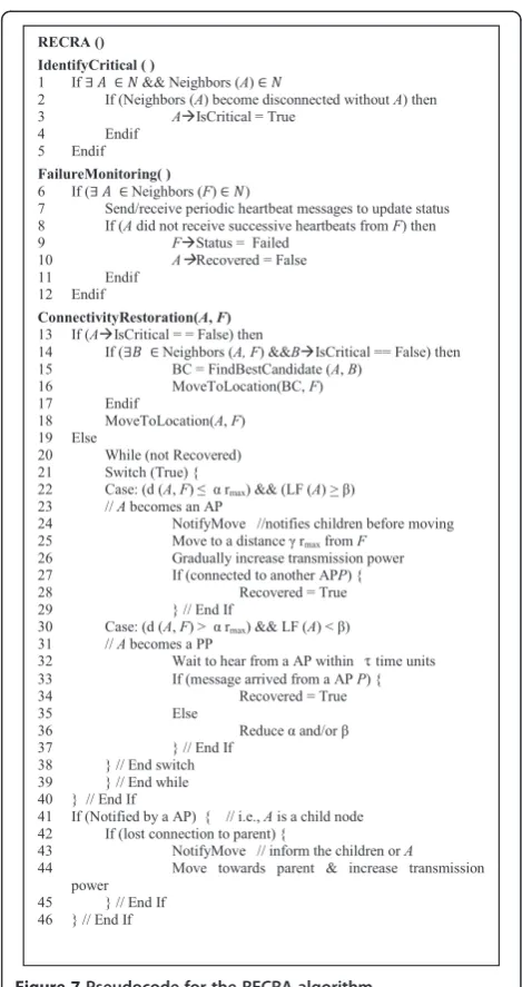
4.4. Pseudocode of RECRA
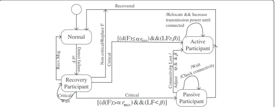
Figure 6 shows a high-level state diagram of RECRA al-gorithm. Upon detecting the failure of a neighbor F, the node switches from normal to recovery participant state. The transition from the recovery participant state would depend on the status, proximity, and LF. A non-critical
N7
node will simply replace the failed node and the recovery will be complete. Critical nodes will wait for the recov-ery message; if received they transition to a normal state and the recovery is complete. Otherwise, a critical recov-ery participant decides its role in the recovrecov-ery based on its proximity and LF. A recovery participant node with close proximity to F and a high LF becomes an AP. Otherwise, the node transition to the PP state and keep tracking progress. In the AP state, a node performs re-location along with increasing transmission power until either it becomes connected with other APs or becomes at a distance γrmax away from F. At the conclusion of the recovery the node switches back to the normal state. In the PP state, nodes wait for APs to re-establish con-nectivity. They continuously monitor the situation for a preset time. If the links are not established, the node times out and transitions to the AP state by increasing the value of α and/or and decreasing β. Again, in AP state it performs the same actions as described above.
Figure 7 shows the pseudocode of RECRA. The algo-rithm is to run on all nodes in a distributed manner. Ini-tially, the status of all nodes is set to non-critical. A node A executes IdentifyCritical() procedure to deter-mine whether it is critical or not based on the localized positional information (lines 1–5). Nodes periodically exchange heartbeat messages with neighbors to update status. If a nodeAdid not receive consecutive heartbeats from neighbor nodeF, it marks theFas failed and sets a flag to indicate that recovery is incomplete (lines 6–12). This mimics the“recovery participant” state in Figure 5. Node A initiates a recovery process. If node A is non-critical, it looks for any other non-critical node that is a common neighbor withF. If there is another non-critical neighbor B with high node degree and least distance to F then B will move to the location of F. Otherwise,
A will replace F and send a recovered message (lines 13–18). The “while” loop (lines 20–39) reflects the actions in the AP and PP states. The loop repeats until the recovery is complete. Lines 22–29 are the steps taken in the AP state where children are notified and the actor moves towards F while increasing the trans-mission power. Otherwise, a PP state is declared in line 30 and the node monitors its connectivity to AP nodes. After waiting for τ time units, a PP node times out and adjusts α and β in order to switch to the AP state. The loop does not terminate until the node sets the “Recovered” indicator to true. The node may not be a neighbor of F and is rather a child to one of the AP nodes (lines 41–46). If node A receives a notifica-tion message from a parent, it watches its link to that parent. If connectivity is lost, the child will move to-wards its parent while increasing transmission power to re-establish the link.
4.5. RECRA algorithm analysis
This section proves the correctness and analyzes the performance of the proposed RECRA algorithm. We introduce the following theorems.
Theorem 1.The network becomes strongly connected if it was strongly connected before a node F fails and if every PP node can reach an AP.
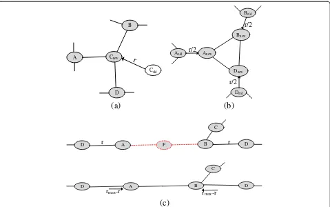
Proof:If the network was strongly connected beforeF fails, every node should have a path to every other node in the network. The failure ofFwill affect the connectiv-ity of the neighbors of F. Moving a non-critical node to the place of F will reestablish the connectivity among the neighbors ofFas shown in Figure 8a. In case of un-availability of non-critical node, establishing links be-tween those neighbors will make the network strongly connected again. When AP nodes move towardsFwhile
/Relocate && Increase
Connectivity Lost / Adjust
y
increasing their communication range until become con-nected. Thus, if every PP can reach an AP node all neighbors of F will be connected again as shown in Figure 8c. In case neighbors ofFare already using their maximum range then moving AP nodes to distance r/2 will connect them as shown in Figure 8b and already proven in RIM [19].
Theorem 2: In RECRA, the total movement distance is:
dn≤rmax,for a non-critical neighbor
dmc≤(rmax−r)
P
i= 0
n
Ci, when nodes can increase their transmission power to rmaxandr>12rmax
dcm≤rmax2 ðN1Þ;For cascaded movement
(assuming none of the neighbor can increase
communication range).
where rmax,n,and N are the communication range,the maximum number of neighbors, and the number of nodes in the network,respectively.
Proof: If any of the neighbors is non-critical, the failed node will simply be replaced Figure 8a. The worst-case scenario is when a non-critical node is located at dis-tance rmax from the failed node F. Hence, the total movement overhead will not exceedrmax. The possibility of having non-critical nodes becomes higher with the increased network density and communication range. Therefore, the performance of RECRA is expected to improve in both the cases.
If there are no non-critical nodes in the neighborhood ofF, nodes move towardsFwhile increasing their com-munication range. The typical case, as articulated in Figure 8c, is when these neighbors are located at dis-tance r from F and are also required to increase their communication range to rmax to sustain connectivity with own neighbors. Therefore, in this case the total dis-tance movement required to rejuvenate connectivity will not exceed (rmax−r)
P
i= 0
n Ci.
The worst recovery scenario is when neighbors of F are critical nodes and are already using their maximum communication range. In this case, the neighbors move
towards F by distance 1
2rmax to become connected. The algorithm is recursively executed on the children of the moved nodes to become connected with parent. The maximum movement overhead will not be more
than rmax
2 ðN1Þ when all healthy nodes in the network are critical and have to move as shown in Figure 8b.
Theorem 3: Participation of a non-critical from any partition or an AP from each partition is sufficient to re-store connectivity irrespective of the number of partitions created.
Proof: There are two cases. In the first case, we may have two or more adjacent non-critical neighbors of F. Replacing F with a non-critical node will restore all the broken links and the recovery is complete as shown in Figure 9a. In the other case, participation of an AP from each partition not only restores connectivity, but also maintains existing communication links with neighbors. For example, Figure 9b illustrates that participation of a node Bfrom partition#1 is not only sufficient to restore connectivity, but it also maintains existing links within the partition.
Theorem 4: RECRA impose maximum movement overhead of rmaxon each recovery participant,where rmax is the maximum communication range of nodes.
critical node travels a maximum distance ofrmaxto sub-stituteFin worst case. While in the latter case, each re-covery participant may have to travel distance rmax/2 in worst case as proven in Theorem 2. Therefore, the max-imum movement overhead in RECRA is rmax because each node moves only once.
Theorem 5:The time for RECRA to successfully restore connectivity is O(f+T),where f is the fault detection la-tency and T is the maximum movement time of any node,which is proportional to rmax.
Proof: In RECRA, the worst-case time complexity is proportional to the failure detection and recovery. Let us
assume that the time to detect a failure or receive a movement notification message is f. In the worst case, the time it takes to establish connectivity is equal to T ¼rmax
2s ðN1Þ where s is the movement speed of nodes and the rmax
2 ðN1Þ is the longest distance travelled by nodes when cascaded relocation is pur-sued, as proved in Theorem 2. Since, the time to increase transmission power is nominal and it is pursued during relocation, therefore, it is included in T. Therefore, the convergence time of RECRA to restore connectivity in the worst case isk(f+T), which isO(f+T).
Cnew
D A
B
Cold
r
r/2
Dold
Aold
Bold
Bnew
Anew
Dnew
r/2
r/2
(a)
(b)
F B
D r A r D
C
B
D A D
rmax-r
rmax-r
C
(c)
Figure 8Illustrating recovery scenarios:(a) non-critical replacement, (b) moving critical inward, (c) failure detection and recovery based on movement and communication.
D
r
D
Aold
Anew
Bold I
Bnew
F r Partition # 1
(a)
(b)
Theorem 6: The message complexity of the RECRA is O(N),where N is the number of nodes in the network.
Proof: RECRA entails one message transmission for each node as it is a localized scheme that only maintains 1-hop neighbor information to restore connectivity. In addition, every AP (i.e., critical node participating in re-covery) has to send one movement notification message to its children so that they can sustain connectivity with the parent and to avoid being wrongfully perceived as faulty. At the new location, the node will send one message to its neighbors. Therefore, in worst case, when all nodes move, the total number of messages will be (N + 2|AP|). Therefore, the message complexity of RECRA is O(N).
5. Experimental evaluation
The effectiveness of the RECRA is validated through ex-tensive simulation experiments. This section describes the experiment setup, performance metrics, and experi-mental results.
5.1. Experiment setup and performance metrics
We have developed a customized simulation environ-ment. In the experiments, we have created topologies that consist of varying number of nodes (20–100). Nodes are randomly placed in an area of 1000 × 600 m2. We have varied the transmission range of nodes (50–125) during experiments. Free space signal propa-gation model and collision-free medium access arbitra-tion are assumed. The performance is assessed using the following metrics.
Thetotal distance movedby all nodes involved in
the recovery: This gauges the efficiency of RECRA in terms of the motion-related overhead, e.g., dissipated energy during recovery.
Thenumber of nodesmoved during the recovery:
This metric reflects the scope of the recovery process the level of disturbance caused to the existing topology. This is crucial specifically in mission-critical applications.
Thenumber of messages exchangedamong nodes:
Again this metric indicates the recovery overhead.
Thepercentage of coverage change(increase or
decrease) relative to the pre-failure level: Although connectivity is the prime objective of RECRA, node coverage is important for many setups. The loss of a node usually has a negative impact on coverage. This metric assesses whether RECRA alleviates or worsens the coverage loss.
Thedegree of connectivityin the network
corresponding to pre-failure level: This metric reflects the level of connectivity that indicates the availability of node-independent paths. It is
measured by averaging the number of neighbors that a node has.
The following parameters were used to vary the net-work configuration in the experiments:
Thenumber of deployed nodes(N) in the network
affects the node density and the inter-node connectivity.
Thenode communication range(r) is the initial
communication range and is equal for all nodes. Whereas,“rmax”is the maximum communication range a node can have.
Thetransmission range utilization ratio(p), which is
defined asr/rmax, affects the connectivity and recovery overhead.
5.2. Baseline approaches
We compare the performance of RECRA to that of DARA [17], RIM [19], and VCR [20] based on the afore-mentioned metrics. Like RECRA, all these approaches are distributed, reactive, and exploit node relocation in order to restore connectivity. However, their procedure is different. When a node F fails, DARA selects a best candidate Aamong its 1-hop neighbors and replaces it. The algorithm is recursively applied to tolerate connect-ivity loss due to movement, i.e., Awill be replaced with one of its neighbors and so on. On the other hand, RIM moves all the 1-hop neighbors towards Funtil they be-come connected. RIM then applies cascaded relocation to re-establish the links that get severed by nodes move-ment. VCR exploits partially utilized transmission power of the 1-hop neighbors besides relocation. A controlled diffusion is applied among recovery participants to in-crease the coverage and limit the repercussions of recovery.
5.3. Simulation results and analysis
addition, the prime objective of this study is to minimize the post-failure recovery. Moreover, we also ran experi-ments in which the failed node is randomly picked in order to assess the impact of inaccuracy of determining critical nodes using 1-hop (RECRA) and 2-hop (DARA) information. In these experiments, “r” and “p” are fixed at 100 m and 25%, respectively. The results of individual experiments are averaged over 20 trials to ensure statis-tically stable results. All results are subject to 90% confi-dence interval analysis and stays within 10% the sample mean.
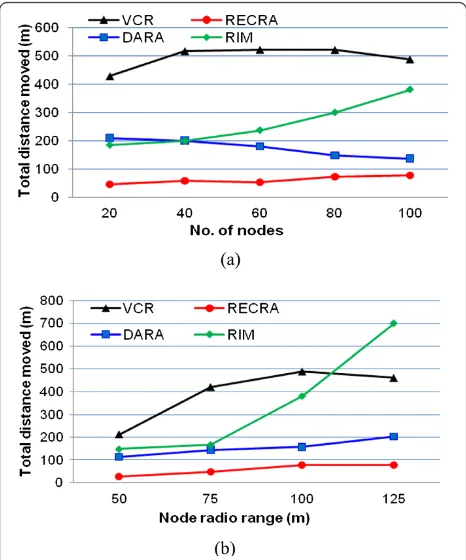
5.3.1. Total traveled distance
The results for the total distance traveled by all nodes until connectivity is restored are shown in Figures 10 and 11, respectively. Figure 10a,b clearly indicates that the performance of RECRA is not much affected by the change in node density and communication range. In addition, RECRA consistently outperforms baseline approaches in terms of the total distance movement. This is because RECRA prefers to employ non-critical nodes in the recovery which does not necessitate cas-caded relocations. Moreover, RECRA strives to limit the involvement of nodes that are far from the failed node and restrain the movement overhead by pursuing higher transmission range. The results demonstrate that RECRA is effective for both sparse and dense networks.
At first glance, one would wonder why the movement overhead is not reduced for higher Nand r. This is be-cause RECRA may choose a distant non-critical node in-stead of moving nearby neighbors that can increase transmission power as is evident from Figure 10b.
Figure 10a indicates that the performance of RECRA scales very well and is not much affected by the node density given the optimized selection of nodes as ex-plained in Section 4.3. In sparse networks, where a non-critical node is not available in the neighborhood, RECRA collectively engages all neighbors of F that can exploit their partially utilized transmission power. On the other hand, RECRA entirely relies on movement in case of a non-critical node in order to minimize scope of recovery as we shall discuss later in this section. Similar observation can be made for the communication range (Figure 10b), where the connectivity-restoration over-head is minor compared to the baseline approaches.
Figure 10 also shows that the performance of RIM and VCR is significantly affected when increasing N and r. This is attributed to the fact that the number of neigh-bors increases in both cases. The self-spreading step in VCR is costly in terms of the motion overhead. This is mainly because the scope of the motion is wider and involves nodes that do not have to relocate for restoring the connectivity. It is worth noting that self-spreading will boost the coverage achieved by VCR as shown later Figure 10Distance traveled by all nodes during the recovery
until restoring connectivity, as a function ofNin (a) andrin (b).
in this section. However, RECRA prefers to minimize movement-related overhead while keeping intact the pre-failure coverage. Figure 10 also indicates that the motion overhead in DARA is slightly more than RECRA. This is because DARA moves least degree nodes that are often critical and results in successive relocations. How-ever, the higher density helps DARA to find leaf nodes and limits the scope of recovery.
Figure 11a reports the impact of critical node detec-tion accuracy which can potentially worsen the perform-ance by unnecessarily triggering recovery of uncritical node. In this experiment, the failed node is randomly picked and the criticality assessment is conducted by ap-plying the algorithm of [27] for DARA and [25] for RECRA using 2-hop and 1-hop information, respect-ively. The performance results show that RECRA still imposes less movement overhead despite the fact that DARA can perform more accurate assessment of the criticality of the failed node, as pointed out in Figure 10a. In sparse networks, the accuracy of deter-mining critical nodes with 1-hop and 2-hop is almost similar, since the node degree is low, and thus the per-formance stays consistent with Figure 10a. However, with high node density, the inaccuracy of critical node detection with 1-hop grows in significance compared to 2-hop due to the increased level of connectivity in the network. That is why the performance of DARA becomes quite closer to RECRA for network with high node count. On the other hand, RECRA may overreact in some cases but it strangles the repercussions through high availability of non-critical nodes.
Figure 11b shows the impact of the transmission range utilization ratio “p” on the movement overhead. Again, the performance of RECRA is almost consistent and far better than VCR. This is mainly because RECRA prefers to engage non-critical nodes and avoids the need to per-form self-spreading. The perper-formance of RECRA is slightly improved with the higher values of “p”. This is expected because nodes reduce their reliance on move-ment and exploit their partially utilized transmission range. On the other hand, the performance of VCR is negatively affected since nodes have to further move away during self-spreading.
5.3.2. Number of moved nodes
Figure 12 shows the number of recovery participants when RECRA and the baseline approaches are applied. The performance graphs confirm the advantage of RECRA which moves fewer nodes than contemporary schemes. This is because it limits the scope of recovery and avoids recursive cascaded relocations by employing non-critical nodes and exploiting partially utilized trans-mission ranges. Moreover, the performance of RECRA remains almost constant while varying the number of
nodes and their radio range, which indicates great scalability.
5.3.3. Number of messages exchanged
Figure 13 reports on the messaging overhead as a func-tion of the network size and radio range. As indicated in the figure, RECRA introduces less messaging overhead compared to the baseline approaches. This is because RECRA prefers to employ non-critical nodes in the re-covery which does not require coordination messages. Moreover, RECRA strives to engage only the closest nodes among 1-hop neighbors of F. On the other hand, Figure 13 indicates that the messaging overhead in RIM significantly grows for a high actor density and long communication range because the number of neighbors increases in both cases.
5.3.4. Percentage of coverage improvement
Figure 14 shows the impact of changing N and r on coverage, measured in terms of percentage of improve-ment relative to the pre-failure level. The sensing/action range is set to 50 m in these experiments. Both figures indicate that RECRA almost preserves the pre-failure coverage despite the fact that the prime concern is source efficiency in terms of recovery overhead. This re-sult is attributed to the fact that neighbors do have overlap coverage with each other depending upon the node density and distribution. Moving an intermediate
non-critical node will only reduce the overlap coverage and occupy the spot vacated due to the failure of F. Moreover, constrained movement of neighbors aroundF inward will also help covers the bare spots. Figure 14a shows that high node density helps RECRA to preserve pre-failure coverage because of availability of intermedi-ate non-critical nodes and overlapped coverage among nodes. However, RECRA struggles to sustain pre-failure coverage in sparse networks because of the aforemen-tioned reason.
On the other hand, increasing the node density in Figure 14a helps DARA and RIM; yet they still do not make up for the coverage loss and definitely do not match RECRA’s performance. DARA prefers to choose the least degree nodes. A node with the least degree is often critical and moving such a node only shifts the coverage hole from one place to another. In RIM, the topology gets shrunk inward which leads to significant loss of coverage at network periphery. Whereas, VCR improves coverage by about 2% and consistently outper-forms both baseline schemes. This coverage advantage of VCR is mainly driven by the diffusion, spreading, of nodes that is performed after connectivity restoration in order to limit the effect of signal interference. Figure 14b indicates that for VCR the coverage grows with the increase in the communication range while the performance of DARA is not affected much. On the other hand, the performance of RIM significantly wor-sens when growing the communication range. With the increased value of r, the network becomes more con-nected and the number of neighbors of F grows. RIM moves nodes inwards making the area around F to be more crowded than at the network periphery and thus cause a significant loss of coverage.
5.3.5. Degree of connectivity
Figure 15 demonstrates the degree of connectivity main-tained by all the approaches relative to the pre-failure level. Again, this metric reflects the average node degree in the network and is measured by averaging the num-ber of neighbors for the individual nodes. Both figures clearly indicate that RECRA consistently maintains the same degree of connectivity as of other approaches, des-pite the fact that the prime objective of RECRA is resource efficient recovery. This is due to moving non-critical nodes, limiting the scope of relocation, and increasing transmission power. Figures 10, 11, 12, 13, and 14 confirm that RECRA strikes a balance between various objectives.
5.4. Important observations
We would like to make few important observations regarding the performance and utility of RECRA. Main-taining network state information at each node (i.e., Figure 13Effect of changingN(a) andr(b) on total number of
messages exchanged by all nodes during the recovery.
1-hop, 2-hop, etc.) dominates the accuracy of determin-ing cut-vertices. The fact that RECRA and DARA main-tain 1-hop and 2-hop information, respectively; therefore, the accuracy of determining cut-vertices in DARA is slightly higher and may cause RECRA to over-react in some cases. However, in dynamic networks, maintaining more network state information at each node consistently requires extra overhead. Since, the prime focus of this study is resource efficient recovery; therefore, RECRA strives to avoid such unnecessary overhead and prefers to engage non-critical and/or nodes with partially utilized transmission range. The ex-perimental results presented above have confirmed the superiority of RECRA over contemporary schemes.
The possibility of simultaneous node failure in MSNs and WSANs is rare; therefore, RECRA is designed to re-cover from a single node failure. In handling simultaneous failures may cause conflicting situations for RECRA where non-critical nodes in the neighborhood are not available.
6. Conclusion and future work
This article has presented a novel distributed resource-efficient connectivity restoration algorithm for MSNs and WSANs. Unlike most published schemes, RECRA exploits availability of non-critical nodes and partially utilized transmission power of nodes besides their re-location. RECRA classifies nodes as critical/non-critical
based on their importance to sustaining connectivity in the network in order to avoid overreacting to non-critical node failures and optimize the recovery from the loss of a critical node. The neighbors of the failed node detect the failure and initiate a recovery process based on their status, proximity, and partially utilized trans-mission power. To minimize the overhead, RECRA pre-fers to employ non-critical nodes by moving them to the place of the failed node. If all neighbors are critical, RECRA employs neighbors of the failed node by increas-ing their transmission power and movincreas-ing them towards the failed node. The performance of RECRA is validated analytically and through extensive simulations. The simulation results have confirmed the effectiveness of RECRA in sparse and dense topologies and its perform-ance advantage over contemporary schemes found in the literature.
In future, we plan to validate the results of RECRA on a prototype network of mobile robots.
Competing interests
The author(s) declare that they have no competing interests.
Authors’contributions
SS designed and coordinated the study; PV, PS, MA, PDA, BAS and SS conducted the experiments and data analysis. PV, BAS and SS wrote the manuscript and all authors read and approved the final manuscript.
Acknowledgment
This work is partially supported by the Chair of Pervasive and Mobile Computing at King Saud University, Saudi Arabia.
Author details
1Deanship of e-Transactions and Communication, King Saud University,
Riyadh, Saudi Arabia.2Department of Computer Science & Electrical Eng,
University of Maryland, Baltimore, MD, USA.3Department of Electrical and
Electronics Eng, Universiti Teknologi PETRONAS, Seri Iskandar, Malaysia.
4College of Computer and Information Sciences, King Saud University,
Riyadh, Saudi Arabia.
Received: 29 May 2012 Accepted: 28 October 2012 Published: 21 November 2012
References
1. I.F. Akyildiz, W. Su, Y. Sankarasubramaniam, E. Cayirci, Wireless sensor networks: a survey. J. Comput. Netw.38(4), 393–422 (2002) 2. M.B. McMickell, B. Goodwine, L.A. Montestruque, MICAbot: a robotic
platform for large-scale distributed robotics, inProceedings of the IEEE International Conference on Robotics and Automation (ICRA '03), ed. by (Taipei, Taiwan, 2003), pp. 1600–1605
3. K. Dantu, M. Rahimi, H. Shah, S. Babel, A. Dhariwal, G.S. Sukhatme, Robomote: enabling mobility in sensor networks, inProceedings of the 4th International Symposium on Information Processing in Sensor Networks (IPSN' 05), ed. by (Los Angeles, CA, USA, 2005), pp. 404–409
4. Robot, http://www.irobot.com
5. S. Yuta, H. Asama, E. Prassler, T. Tsubouchi, S. Thrun, M. Diel, D. Hahnel,Scan alignment and 3-D surface modeling with a helicopter platform, in Field and Service Robotics, 24th edn. (Springer Berlin, Heidelberg, 2006), pp. 287–297 6. G. Wang, G. Cao, T.L. Porta, W. Zhang, Sensor relocation in mobile sensor
networks, inProceedings of the IEEE 24th Annual Joint Conference of the IEEE Computer and Communications Societies (INFOCOM 2005), 4th edn. (Miami, 2005), pp. 2302–2312
7. I.F. Akyildiz, I.H. Kasimoglu, Wireless sensor and actor networks: research challenges. J. Ad Hoc Netw.2(4), 351–367 (2004)
8. CC1000 A unique UHF RF Transceiver. http://www.chipcon.com
9. CC2420 2.4 GHz IEEE 802.15.4 ZigBee-ready RF Transceiver. http://www. chipcon.com
10. M. Imran, M. Younis, A.M. Said, H. Hasbullah, Localized motion-based connectivity restoration algorithms for wireless sensor and actor networks. J. Netw. Comput. Appl.35(2), 844–856 (2012)
11. K. Ozaki, K. Watanabe, S. Itaya, N. Hayashibara, T. Enokido, M. Takizawa,A fault-tolerant model for wireless sensor-actor system, in Proceedings of the 20th International Conference on Advanced Information Networking and Applications (AINA 2006), vol. 2(Vienna, 2006), pp. 303–307 12. R. Ramanathan, R. Rosales-Hain,Topology control of multihop wireless
networks using transmit power adjustment, in Proceedings of the IEEE 19th Annual Joint Conference of the IEEE Computer and Communications Societies (INFOCOM 2000), 2nd edn. (Tel Aviv, 2000), pp. 404–413
13. N. Li, J.C. Hou,Topology control in heterogeneous wireless networks: problems and solutions, in Proceedings of the 23rd Annual Joint Conference of the IEEE Computer and Communications Societies (INFOCOM' 04)(Hong Kong, 2004), pp. 232–243
14. M. Younis, K. Akkaya, Strategies and techniques for node placement in wireless sensor networks: a survey. J. Ad Hoc Netw.6(4), 621–655 (2008) 15. P. Basu, J. Redi, Movement control algorithms for realization of fault-tolerant
ad hoc robot networks. J. IEEE Netw.18(4), 36–44 (2004)
16. D. Shantanu, L. Hai, K. Ajith, N. Amiya, I. Stojmenovic,Localized movement control for fault tolerance of mobile robot networks, in Proceedings of The First IFIP International Conference on Wireless Sensor and Actor Networks (WSAN 2007)(Albacete, 2007), pp. 1–12
17. A.A. Abbasi, K. Akkaya, M. Younis,A distributed connectivity restoration algorithm in wireless sensor and actor networks, in Proceedings of the 32nd IEEE Conference on Local Computer Networks (LCN' 07)(Dublin, Ireland, 2007), pp. 496–503
18. A. Alfadhly, U.A. Baroudi, M. Younis,Least distance movement recovery approach for large scale wireless sensor and actor networks, in Proceedings of the 7th International Wireless Communications and Mobile Computing Conference (IWCMC'11)(Istanbul, 2011), pp. 2058–2063
19. M. Younis, S. Lee, S. Gupta, K. Fisher,A localized self-healing algorithm for networks of moveable sensor nodes, in Proceedings of the IEEE Global Telecommunications Conference (GLOBECOM' 08)(LA, 2008), pp. 1–5 20. M. Imran, M. Younis, A. Md Said, H. Hasbullah,Volunteer-instigated
connectivity restoration algorithm for wireless sensor and actor networks, in Proceedings of the 2010 IEEE International Conference on Wireless Communications, Networking and Information Security (WCNIS)
(Beijing, 2010), pp. 679–683
21. N. Tamboli, M. Younis, Coverage-aware connectivity restoration in mobile sensor networks. J. Netw. Comput. Appl.33(4), 363–374 (2010)
22. K. Akkaya, S. Janapala, Maximizing connected coverage via controlled actor relocation in wireless sensor and actor networks. J. Comput. Netw.
52(14), 2779–2796 (2008)
23. M. Duque-Anton, F. Bruyaux, P. Semal, Measuring the survivability of a network: connectivity and rest-connectivity. Eur. Trans. Telecommun.
11(2), 149–159 (2000)
24. D. Goyal, J.J. Caffery,Partitioning avoidance in mobile ad hoc networks using network survivability concepts, in Proceedings of the Seventh International Symposium on Computers and Communications (ISCC'02)(Giardini Naxos, 2002), pp. 553–558
25. M. Jorgic, I. Stojmenovic, M. Hauspie, D. Simplot-ryl,Localized algorithms for detection of critical nodes and links for connectivity in ad hoc networks, in Proceedings of the 3rd Annual IFIP Mediterranean Ad Hoc Networking Workshop (Med-Hoc-Net)(Bodrum, 2004), pp. 360–371
26. L.H.A. Correia, D.F. Macedo, A.L. dos Santos, A.A.F. Loureiro, J.M.S. Nogueira, Transmission power control techniques for wireless sensor networks. Comput. Netw.51(17), 4765–4779 (2007)
27. X. Liu, L. Xiao, A. Kreling, Y. Liu,Optimizing overlay topology by reducing cut vertices, in Proceedings of the 2006 International Workshop on Network and Operating Systems Support for Digital Audio and Video(Rhode Island, USA, 2006)
doi:10.1186/1687-1499-2012-347
Cite this article as:Imranet al.:Resource efficient connectivity restoration algorithm for mobile sensor/actor networks.EURASIP Journal on Wireless Communications and Networking20122012:347.
Submit your manuscript to a
journal and benefi t from:
7Convenient online submission
7Rigorous peer review
7Immediate publication on acceptance
7Open access: articles freely available online
7High visibility within the fi eld
7Retaining the copyright to your article