Management A
nd Contr
ol
of a DC Micro-Grid
Based Wind Power Generation System
Abstract—This paper presents the design of a dc grid-based wind
power generation system in a poultry farm. The proposed system allows flexible operation of multiple parallel-connected wind gen-erators by eliminating the need for voltage and frequency synchro-nization. A model predictive control algorithm that offers better transient response with respect to the changes in the operating conditions is proposed for the control of the inverters. The design concept is verified through various test scenarios to demonstrate the operational capability of the proposed microgrid when it oper-ates connected to and islanded from the distribution grid, and the results obtained are discussed.
Index Terms—Wind power generation, dc grid, energy
manage-ment, model predictive control.
I. INTRODUCTION
Poultryfarming is the raising of domesticated birds such as chickens and ducks for the purpose of farming meat orfarm eggs for food. To ensure that the poultries remain productive, the poultry farms in Singapore are required to be maintained at a comfortable temperature. Cooling fans, with power ratings of tens of kilowatts, are usually installed to regulate the tempera-ture in the farms [1]–[3]. Besides cooling the farms, the wind energy produced by the cooling fans can be harnessed using wind turbines (WTs) to reduce the farms’ demand on the grid. The Singapore government is actively promoting this new con-cept of harvesting wind energy from electric ventilation fans in poultry farms which has been implemented in many countries around the world [4]. The major difference between the situa-tion in poultry farms and common wind farms is in the wind speed variability. The variability of wind speed in wind farms directly depends on the environmental and weather conditions while the wind speed in poultry farms is generally stable as it is generated by constant-speed ventilation fans. Thus, the genera-tion intermittency issues that affect the reliability of electricity supply and power balance are not prevalent in poultry farm wind energy systems.
In recent years, the research attention on dc grids has been resurging due to technological advancements in power electron-ics and energy storage devices, and increase in the variety of dc loads and the penetration of dc distributed energy resources (DERs) such as solar photovoltaics and fuel cells.
Many research works on dc microgrids have been conducted to facilitate the integration of various DERs and energy storage systems. In [5], [6], a dc microgrid based wind farm architecture in which each wind energy conversion unit consisting of a ma-trix converter, a high frequency transformer and a single-phase ac/dc converter is proposed. However, the proposed architecture increases the system complexity as three stages of conversion are required. In [7], a dc microgrid based wind farm architec-ture in which the WTs are clustered into groups of four with each group connected to a converter is proposed. However, with the proposed architecture, the failure of one converter will re-sult in all four WTs of the same group to be out of service. The research works conducted in [8]–[10] are focused on the development of different distributed control strategies to coordi-nate the operation of various DERs and energy storage systems in dc microgrids. These research works aim to overcome the challenge of achieving a decentralized control operation using only local variables. However, the DERs in dc microgrids are strongly coupled to each other and there must be a minimum level of coordination between the DERs and the controllers. In [11], [12], a hybrid ac/dc grid architecture that consists of both ac and dc networks connected together by a bidirectional converter is proposed. Hierarchical control algorithms are incorporated to ensure smooth power transfer between the ac microgrid and the dc microgrid under various operating conditions. However, failure of the bidirectional converter will result in the isolation of the dc microgrid from the ac microgrid.
An alternative solution using a dc grid based distribution network where the ac outputs of the wind generators (WGs) in a poultry farm are rectified to a common voltage at the dc grid is proposed in this paper. The most significant advantage of the proposed system is that only the voltage at the dc grid has to be controlled for parallel operation of several WGs without the need to synchronize the voltage, frequency and phase, thus allowing the WGs to be turned ON or OFF anytime without causing any disruptions.
Many research works on designing the controllers for the control of inverters in a microgrid during grid-connected and islanded operations is conducted in [13]–[15]. A commonly adopted control scheme which is detailed in [13], [14] contains an inner voltage and current loop and an external power loop to regulate the output voltage and the power flow of the inverters. In [15], a control scheme which uses separate controllers for
Mr.Ramu Joga, M.Tech, [email protected]
Asst. Professor,
SWATHI INSTITUTE OF TECHNOLOGY AND SCIENCES
Blatasingaram, Hayat Nagar, Rangareddy District, Hyderabad, Telangana-500075
the inverters during grid-connected and islanded operations is proposed. Although there are a lot of research works being con-ducted on the development of primary control strategies for DG units, there are many areas that require further improvement and research attention. These areas include improving the robustness of the controllers to topological and parametric uncertainties, and improving the transient response of the controllers.
To increase the controller’s robustness against variations in the operating conditions when the microgrid operates in the grid-connected or islanded mode of operation as well as its ca-pability to handle constraints, a model-based model predictive control (MPC) design is proposed in this paper for controlling the inverters. As the microgrid is required to operate stably in different operating conditions, the deployment of MPC for the control of the inverters offers better transient response with re-spect to the changes in the operating conditions and ensures a more robust microgrid operation. There are some research works on the implementation of MPC for the control of invert-ers. In [16], a finite control set MPC scheme which allows for the control of different converters without the need of additional modulation techniques or internal cascade control loops is pre-sented but the research work does not consider parallel operation of power converters. In [17], an investigation on the usefulness of the MPC in the control of parallel-connected inverters is con-ducted. The research work is, however, focused mainly on the control of inverters for uninterruptible power supplies in stand-alone operation. The MPC algorithm will operate the inverters close to their operating limits to achieve a more superior perfor-mance as compared to other control methods which are usually conservative in handling constraints [18], [19]. In this paper, the inverters are controlled to track periodic current and volt-age references and the control signals have a limited operating range. Under such operating condition, the MPC algorithm is operating close to its operating limits where the constraints will be triggered repetitively. In conventional practices, the control signals are clipped to stay within the constraints, thus the sys-tem will operate at the sub-optimal point. This results in inferior performance and increases the steady-state loss. MPC, on the contrary, tends to make the closed-loop system operate near its limits and hence produces far better performance. MPC has also been receiving increased research attention for its applications in energy management of microgrids because it is a multi-input, multi-output control method and allows for the implementation of control actions that predict future events such as variations in power generation by intermittent DERs, energy prices and load demands [20]–[22]. In these research works, the management of energy is formulated into different multi-objective optimiza-tion problems and different MPC strategies are proposed to solve these optimization problems. The scope of this paper is however focused on the application of MPC for the control of inverters.
In what follows, a comprehensive solution for the operation of a dc grid based wind power generation system in a microgrid is proposed for a poultry farm and the effectiveness of the proposed system is verified by simulation studies under different operating conditions.
II. SYSTEMDESCRIPTION ANDMODELING
A. System Description
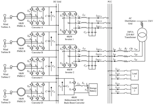
The overall configuration of the proposed dc grid based wind power generation system for the poultry farm is shown in Fig. 1. The system can operate either connected to or islanded from the distribution grid and consists of four 10 kW permanent magnet synchronous generators (PMSGs) which are driven by the variable speed WTs. The PMSG is considered in this paper because it does not require a dc excitation system that will increase the design complexity of the control hardware. The three-phase output of each PMSG is connected to a three-phase converter (i.e., converters A, B, C and D), which operates as a rectifier to regulate the dc output voltage of each PMSG to the desired level at the dc grid. The aggregated power at the dc grid is inverted by two inverters (i.e., inverters 1 and 2) with each rated at 40 kW. Instead of using individual inverter at the output of each WG, the use of two inverters between the dc grid and the ac grid is proposed. This architecture minimizes the need to synchronize the frequency, voltage and phase, reduces the need for multiple inverters at the generation side, and provides the flexibility for the plug and play connection of WGs to the dc grid. The availability of the dc grid will also enable the supply of power to dc loads more efficiently by reducing another ac/dc conversion.
The coordination of the converters and inverters is achieved through a centralized energy management system (EMS). The EMS controls and monitors the power dispatch by each WG and the load power consumption in the microgrid through a centralized server. To prevent excessive circulating currents be-tween the inverters, the inverter output voltages of inverters 1 and 2 are regulated to the same voltage. Through the EMS, the output voltages of inverters 1 and 2 are continuously monitored to ensure that the inverters maintain the same output voltages. The centralized EMS is also responsible for other aspects of power management such as load forecasting, unit commitment, economic dispatch and optimum power flow. Important infor-mation such as field measurements from smart meters, trans-former tap positions and circuit breaker status are all sent to the centralized server for processing through wireline/wireless communication. During normal operation, the two inverters will share the maximum output from the PMSGs (i.e., each inverter shares 20 kW). The maximum power generated by each WT is estimated from the optimal wind power Pw t,opt as follows [23]:
Pw t,opt= kopt(ωr,opt)3 (1)
kopt=
1
2Cp,optρA
R
λopt
3
(2)
ωr,opt= λopt v
R (3)
Fig. 1. Overall configuration of the proposed dc grid based wind power generation system in a microgrid.
wind speed and R is the radius of the blade. When one inverter fails to operate or is under maintenance, the other inverter can handle the maximum power output of 40 kW from the PMSGs. Thus the proposed topology offers increased reliability and en-sures continuous operation of the wind power generation system when either inverter 1 or inverter 2 is disconnected from opera-tion. An 80 Ah storage battery (SB), which is sized according to [24], is connected to the dc grid through a 40 kW bidirectional dc/dc buck-boost converter to facilitate the charging and dis-charging operations when the microgrid operates connected to or islanded from the grid. The energy constraints of the SB in the proposed dc grid are determined based on the system-on-a-chip (SOC) limits given by
SOCm in<SOC≤SOCm ax (4) Although the SOC of the SB cannot be directly measured, it can be determined through the estimation methods as detailed in [25], [26]. With the use of a dc grid, the impact of fluctuations between power generation and demand can be reduced as the SB can swiftly come online to regulate the voltage at the dc grid. During off-peak periods when the electricity demand is low, the SB is charged up by the excess power generated by the WTs. Conversely, during peak periods when the electricity demand is high, the SB will supplement the generation of the WTs to the loads.
B. System Operation
When the microgrid is operating connected to the distribution grid, the WTs in the microgrid are responsible for providing local power support to the loads, thus reducing the burden of power delivered from the grid. The SB can be controlled to achieve different demand side management functions such as peak shaving and valley filling depending on the time-of-use of electricity and SOC of the SB [27]–[29].
During islanded operation where the CBs disconnect the mi-crogrid from the distribution grid, the WTs and the SB are only available sources to supply the load demand. The SB can supply for the deficit in real power to maintain the power balance of the microgrid as follows:
Pw t+Psb=Ploss+Pl (5) wherePw t is the real power generated by the WTs,Psbis the real power supplied by SB which is subjected to the constraint of the SB maximum powerPsb,m axthat can be delivered during discharging and is given by
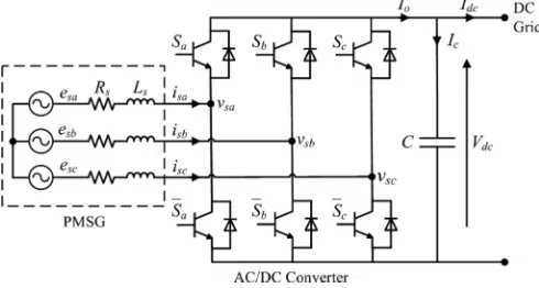
Fig. 2. Power circuit of a PMSG connected to an ac/dc voltage source con-verter.
C. AC/DC Converter Modeling
Fig. 2 shows the power circuit consisting of a PMSG which is connected to an ac/dc voltage source converter. The PMSG is modeled as a balanced three-phase ac voltage sourceesa, esb, esc with series resistanceRsand inductanceLs[30], [31]. As shown in [32], the state equations for the PMSG currentsisa, isb, isc and the dc output voltageVdc of the converter can be expressed as follows:
Ls dis
dt = −Rsis+es−KSVdc (7) CdVdc
dt =i T
sS−Idc (8) where
is =
isa isb isc
T , es =
esa esb esc
T
K=
⎡ ⎢ ⎢ ⎣
2/3 −1/3 −1/3 −1/3 2/3 −1/3 −1/3 −1/3 2/3
⎤ ⎥ ⎥ ⎦
S=Sa Sb Sc
T
is the ac/dc converter switching functions which are defined as
Sj =
1, Sj is ON
0, Sj is OFF
for j=a, b, c (9)
D. DC/AC Inverter Modeling
The two 40 kW three-phase dc/ac inverters which connect the dc grid to the point of common coupling (PCC) are identical, and the single-phase representation of the three-phase dc/ac inverter is shown in Fig. 3. To derive a state-space model for the inverter, Kirchhoff’s voltage and current laws are applied to loop i and point x respectively, and the following equations are obtained:
Lf di
dt+iR+vD G = uVdc (10) iD G = i−iCf (11)
whereVdcis the dc grid voltage, u is the control signal, R is the inverter loss,Lf andCf are the inductance and capacitance of the low-pass (LPF) filter respectively,iD Gis the inverter output
Fig. 3. Single-phase representation of the three-phase dc/ac inverter.
current, i is the current flowing throughLf, iCf is the current
flowing throughCf, andvD G is the inverter output voltage. During grid-connected operation, the inverters are connected to the distribution grid and are operated in the current control mode (CCM) because the magnitude and the frequency of the output voltage are tied to the grid voltage. Thus, the discrete state-space equations for the inverter model operating in the CCM can be expressed with sampling timeTsas follows:
xg(k+ 1) = Agxg(k) +Bg1vg(k) +Bg2ug(k) (12) yg(k) = Cgxg(k) +Dgvg(k) (13) where the subscript g represents the inverter model during grid-connected operation, k is the discretized present time step, and
Ag = 1− R Lf
Ts, Bg1 =
0 −Ts
Lf
, Bg2 = Vdc
Lf Ts
Cg = 1, Dg =
Cf
Ts −
Cf
Ts
xg(k) =i(k) is the state vector; vg(k) = [vD G(k+ 1) vD G(k)]T is the exogenous input; ug(k) is the control signal with−1≤ug(k)≤1; andyg(k) =iD G(k)is the output. The exogenous inputvg(k)can be calculated using state estimation. In this paper, the grid is set as a large power system, which means that the grid voltage is a stable three-phase sinusoidal voltage. Hence, when operating in the CCM, a three-phase sinusoidal signal can be used directly as the exogenous input.
During islanded operation, the inverters will be operated in the voltage control mode (VCM). The voltage of the PCC will be maintained by the inverters when the microgrid is islanded from the grid. As compared to Ts, the rate of change of the inverter output current is much slower. Therefore, the following assumption is made when deriving the state-space equations for the inverter operating in the VCM [33]:
diD G
dt = 0. (14)
Fig. 4. Configuration of the proposed controller for the ac/dc converter.
be expressed as follows:
xi(k+ 1) = Aixi(k) +Biui(k) (15) yi(k) = Cixi(k) (16) where the subscript i represents the model of the inverter during islanded operation and
Ai =
⎡ ⎢ ⎢ ⎢ ⎢ ⎢ ⎣
1− R
Lf Ts −
Ts Lf
0
Ts Lf
1 −Ts
Cf
0 0 1
⎤ ⎥ ⎥ ⎥ ⎥ ⎥ ⎦
, Bi=
Vdc Lf
Ts 0 0
Ci =
0 1 0
xi(k) =
i(k)vD G(k)iD G(k)
T
is the state vector; ui(k)is the control signal with−1≤ui(k)≤1; andyi(k) =vD G(k)is the output. During islanded operation, the inverters are required to deliver all the available power from the PMSGs to the loads. Therefore, only the inverter output voltage is controlled and the output current is determined from the amount of available power.
III. CONTROLDESIGN
A. Control Design for the AC/DC Converter
Fig. 4 shows the configuration of the proposed controller for each ac/dc voltage source converter which is employed to maintain the dc output voltageVdc of each converter and com-pensate for any variation inVdc due to any power imbalance in the dc grid. The power imbalance will induce a voltage error
(Vdc∗ −Vdc)at the dc grid, which is then fed into a proportional-integral controller to generate a current reference i∗d for id to track. To eliminate the presence of high frequency switching ripples at the dc grid,Vdc is first passed through a first-order LPF. The currentiq is controlled to be zero so that the PMSG only delivers real power. The current errors Δid andΔiq are then converted into the abc frame and fed into a proportional-resonant (PR) controller to generate the required control signals using pulse-width modulation.
B. Control Design for the DC/AC Inverter
In order for the microgrid to operate in both grid-connected and islanded modes of operation, a model-based controller us-ing MPC is proposed for the control of the inverters. MPC is a model-based controller and adopts a receding horizon approach in which the optimization algorithm will compute a sequence of control actions to minimize the selected objectives for the whole control horizon, but only execute the first control action for the inverter. At the next time step, the optimization process is repeated based on new measurements over a shifted predic-tion horizon. By doing so, MPC can make the output track the reference at the next step, as well as plan and correct its control signals along the control process. This will guarantee a better transient response compared to conventional PID/PR con-trollers [32], [33]. To derive the control algorithm for the invert-ers, the state-space equations are transformed into augmented state-space equations by defining the incremental variables in the following format:
Δξ(k) =ξ(k)−ξ(k−1) (17)
whereξrepresents each variable in the inverter model, such as vD G, iD G, i and u as shown in Fig. 3.
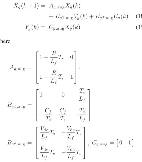
By defining the incremental variables, the augmented state-space model for the inverter model operating in the CCM during grid-connected operation can be expressed as follows:
Xg(k+ 1) = AgaugXg(k)
+Bg1 augVg(k) +Bg2 augUg(k) (18) Yg(k) = CgaugXg(k) (19)
where
Agaug =
⎡ ⎢ ⎢ ⎢ ⎣
1− R
Lf Ts 0
1− R
Lf Ts 1
⎤ ⎥ ⎥ ⎥ ⎦,
Bg1 aug =
⎡ ⎢ ⎢ ⎢ ⎣
0 0 −Ts
Lf
−Cf Ts
Cf Ts −
Ts Lf ⎤ ⎥ ⎥ ⎥ ⎦
Bg2 aug =
⎡ ⎢ ⎢ ⎢ ⎣ Vdc Lf
Ts − Vdc Lf
Ts
Vdc Lf
Ts − Vdc Lf Ts ⎤ ⎥ ⎥ ⎥
⎦, Cgaug =
0 1
Xg(k) =
Δi(k)iD G(k)
T
is the state vector; Vg(k) =
ΔvD G(k+ 2) ΔvD G(k+ 1) ΔvD G(k)
T
is the exogenous input; Ug(k) = Δug(k) is the control signal; and Yg(k) = iD G(k)is the output.
expressed as follows:
Xi(k+ 1) = AiaugXi(k) +BiaugUi(k) (20) Yi(k) = CiaugXi(k) (21) where
Aiaug =
⎡ ⎢ ⎢ ⎢ ⎢ ⎢ ⎢ ⎢ ⎢ ⎢ ⎢ ⎢ ⎢ ⎢ ⎣
1− R
Lf Ts −
Ts Lf
0 0
Ts Lf
1 −Ts
Lf
0
0 0 1 0
Ts Lf
1 Ts
Lf 1 ⎤ ⎥ ⎥ ⎥ ⎥ ⎥ ⎥ ⎥ ⎥ ⎥ ⎥ ⎥ ⎥ ⎥ ⎦ ,
Biaug =
⎡ ⎢ ⎢ ⎢ ⎢ ⎢ ⎢ ⎢ ⎢ ⎢ ⎢ ⎣ Vdc Lf Ts 0 0 0 ⎤ ⎥ ⎥ ⎥ ⎥ ⎥ ⎥ ⎥ ⎥ ⎥ ⎥ ⎦
, Ciaug=
0 0 0 1
Xi(k) =
Δi(k) ΔvD G(k) ΔiD G(k)vD G(k)
T
is the state vector; Ui(k) = Δui(k) is the control signal; and Yi(k) = vD G(k)is the output.
For the control of the two augmented models in the CCM and the VCM, the following cost function is solved using quadratic programming in the proposed MPC algorithm [33]:
J = (Rs−Yj)T(Rs−Yj) +UjTQUj (22) subject to the constraint
−1≤uj(k)≤1 (23) whereRsis the set-point matrix, Q is the tuning matrix for the desired closed-loop performance,Yj is the output of either the augmented model in the CCM or VCM (i.e.,Yg or Yi),Uj is the control signal of either the augmented model in the CCM or VCM (i.e., Ug or Ui). The first part of the cost function is to compare the output of the augmented modelYj with the referenceRs and to ensure that the output tracks the reference with minimum error. The second part of the cost function is to calculate the weighted factor of the control signal and to ensure that the control signal generated by the MPC algorithm is within the constraints. The quadratic programming will ensure that the optimal solution for the control signal deviationΔu is achieved while minimizing the cost function J. After the control signal u is generated by the MPC algorithm, it will be applied to the dc/ac inverter as shown in Fig. 3.
IV. NUMERICALSIMULATIONANALYSIS
The simulation model of the proposed dc grid based wind power generation system shown in Fig. 1 is implemented in
TABLE I
PARAMETERS OF THEPROPOSEDSYSTEM
Parameter Value
Distribution grid voltage vg = 230V (phase)
DC grid voltage Vd c= 500V
PMSG stator impedance Rs= 0.2 Ω,Ls= 2.4mH
Distribution line impedance R= 7.5mΩ,L= 25.7μH
Inverter LC filter Lf= 1.2mH,Cf = 20μF
Converter capacitor C= 300μF
Converter and inverter loss resistance R= 1mΩ
Load 1 rating PL1= 35kW,QL1= 8kVAr
Load 2 rating PL2= 25kW,QL2= 4kVAr
MATLAB/Simulink. The effectiveness of the proposed design concept is evaluated under different operating conditions when the microgrid is operating in the grid-connected or islanded mode of operation. The system parameters are given in Table I. The impedances of the distribution line are obtained from [34]. In practical implementations, the values of the converter and inverter loss resistance are not precisely known. Therefore, these values have been coarsely estimated.
A. Test Case 1: Failure of One Inverter During Grid-Connected Operation
When the microgrid is operating in the grid-connected mode of operation, the proposed wind power generation system will supply power to meet part of the load demand. Under normal operating condition, the total power generated by the PMSGs at the dc grid is converted by inverters 1 and 2 which will share the total power supplied to the loads. When one of the inverters fails to operate and needs to be disconnected from the dc grid, the other inverter is required to handle all the power generated by the PMSGs. In this test case, an analysis on the microgrid operation when one of the inverters is disconnected from operation is conducted.
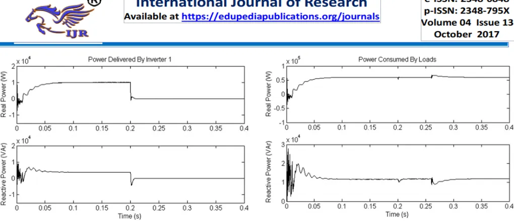
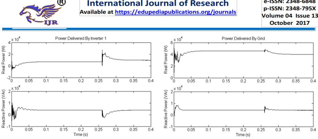
Fig. 5. Real (top) and reactive (bottom) power delivered by inverter 1.
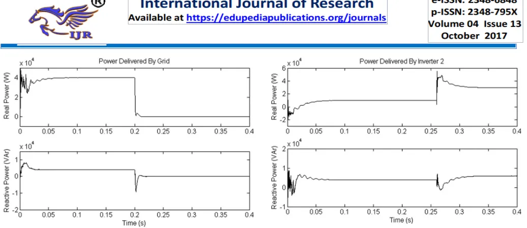
Fig. 6. Real (top) and reactive (bottom) power delivered by inverter 2.
Fig. 7. Real (top) and reactive (bottom) power delivered by the grid.
model-based MPC control. Essentially, model-based control schemes are able to take into account the system parameters such that the overall performance can be optimized.
Att= 0.2s, inverter 1 fails to operate and is disconnected from the microgrid, resulting in a loss of 10 kW of real power and 4 kVAr of reactive power supplied to the loads. As shown
Fig. 8. Real (top) and reactive (bottom) power consumed by the loads.
Fig. 9. DC grid voltage.
in Fig. 5, the real and reactive power supplied by inverter 1 is decreased to zero in about half a cycle after inverter 1 is discon-nected. This undelivered power causes a sudden power surge in the dc grid which corresponds to a voltage rise att= 0.2 s as shown in Fig. 9. To ensure that the load demand is met, the grid automatically increases its real and reactive power generation to 50 kW and 8 kVAr respectively att= 0.2s, as shown in Fig. 7. Att= 0.26s, the EMS of the microgrid increases the reference real and reactive power supplied by inverter 2 to 20 kW and 8 kVAr respectively. A delay of three cycles is introduced to cater for the response time of the EMS to the loss of inverter 1. As shown in Fig. 6, inverter 2 manages to increase its real and reactive power supplied to the loads to 20 kW and 8 kVAr for0.26≤t <0.4s. At the same time, the grid decreases its real and reactive power back to 40 kW and 4 kVAr as shown in Fig. 7 respectively. The power balance in the microgrid is restored after three cycles fromt= 0.26s. It is observed from Fig. 9 that the voltage at the dc grid corresponds to a voltage dip att= 0.26s due to the increase in power drawn by inverter 2 and then returns to its nominal value of 500 V for0.26≤t <0.4s. As observed in Fig. 8, att= 0.26s, the changes in power deliv-ered by inverter 2 and the grid also cause a transient in the load power.
B. Test Case 2: Connection of AC/DC Converter During Grid-Connected Operation
Fig. 10. Real (top) and reactive (bottom) power delivered by inverter 1.
Fig. 11. Real (top) and reactive (bottom) power delivered by inverter 2.
of any PMSGs to the microgrid without the need to synchronize their voltage and frequency. This capability is demonstrated in this case study.
The microgrid operates connected to the grid and PMSG A is disconnected from the dc grid for0≤t <0.2s as shown in Fig. 1. The real power generated from each of the remaining three PMSGs is maintained at 5.5 kW and their aggregated real power of 16.5 kW at the dc grid is converted by inverters 1 and 2 into 14 kW of real power and 8 kVAr of reactive power. As shown in Figs. 10 and 11, each inverter delivers real and reactive power of 7 kW and 4 kVAr to the loads respectively. The rest of the real and reactive power demand of the loads is supplied by the grid as shown in Fig. 12. It can be seen from Fig. 12 that the grid delivers 46 kW of real power and 4 kVAr of reactive power to the loads.
Att= 0.2s, PMSG A which generates real power of 5.5 kW is connected to the dc grid. This causes a sudden power surge at the dc grid and results in a voltage rise att= 0.2s as shown in the voltage waveform of Fig. 13. At t= 0.26s, the EMS increases the real delivered by each inverter to 10 kW while the reactive power supplied by each inverter remains unchanged at 4 kVAr as shown in Figs. 10 and 11. This causes a momentarily
Fig. 12. Real (top) and reactive (bottom) power delivered by the grid.
Fig. 13. DC grid voltage.
dip in the dc grid voltage att= 0.26s as observed in Fig. 13 which is then restored back to its nominal voltage of 500 V for0.26≤t <0.4s. The grid also simultaneously decreases its supply to 40 kW of real power for 0.26≤t <0.4 s while its reactive power remains constant at 4 kVAr as shown in Fig. 12.
C. Test Case 3: Islanded Operation
When the microgrid operates islanded from the distribution grid, the total generation from the PMSGs will be insuffi-cient to supply for all the load demand. Under this condition, the SB is required to dispatch the necessary power to ensure that the microgrid continues to operate stably. The third case study shows the microgrid operation when it islands from the grid.
Fig. 14. Real (top) and reactive (bottom) power delivered by the grid.
Fig. 15. Real (top) and reactive (bottom) power delivered by inverter 1.
supply real power of 40 kW att= 0.26s as shown in Fig. 17. At the same time, the real and reactive power delivered by each inverter is also increased by the EMS to 30 kW and 6 kVAr as shown in Figs. 15 and 16 respectively. Fig. 18 shows the dc grid voltage where slight voltage fluctuations are observed at t= 0.26s. The initial voltage rise at t= 0.26s is due to the power supplied by the SB while the subsequent voltage dip is due to the increase in power drawn by the inverters.
V. CONCLUSION
In this paper, the design of a dc grid based wind power gen-eration system in a microgrid that enables parallel opgen-eration of several WGs in a poultry farm has been presented. As compared to conventional wind power generation systems, the proposed microgrid architecture eliminates the need for voltage and fre-quency synchronization, thus allowing the WGs to be switched on or off with minimal disturbances to the microgrid opera-tion. The design concept has been verified through various test scenarios to demonstrate the operational capability of the pro-posed microgrid and the simulation results has shown that the proposed design concept is able to offer increased flexibility
Fig. 16. Real (top) and reactive (bottom) power delivered by inverter 2.
Fig. 17. Real power delivered by SB.
Fig. 18. DC grid voltage.
and reliability to the operation of the microgrid. However, the proposed control design still requires further experimental val-idation because measurement errors due to inaccuracies of the voltage and current sensors, and modeling errors due to varia-tions in actual system parameters such as distribution line and transformer impedances will affect the performance of the con-troller in practical implementation. In addition, MPC relies on the accuracy of model establishment, hence further research on improving the controller robustness to modeling inaccuracy is required. The simulation results obtained and the analysis per-formed in this paper serve as a basis for the design of a dc grid based wind power generation system in a microgrid.
REFERENCES
[1] M. Czarick and J. Worley, “Wind turbines and tunnel fans,” Poultry Hous-ing Tips, vol. 22, no. 7, pp. 1–2, Jun. 2010.
[3] Livestock and climate change. [Online]. Available: http://www. worldwatch.org/files/pdf/Livestock%20and%20Climate%20Change.pdf. [4] Farm Energy: Energy efficient fans for poultry production.[Online].
Avail-able: http://farmenergy.exnet.iastate.edu.
[5] A. Mogstad, M. Molinas, P. Olsen, and R. Nilsen, “A power conversion system for offshore wind parks,” in Proc. 34th IEEE Ind. Electron., 2008, pp. 2106–2112.
[6] A. Mogstad and M. Molinas, “Power collection and integration on the electric grid from offshore wind parks,” in Proc. Nordic Workshop Power Ind. Electron., 2008, pp. 1–8.
[7] D. Jovic, “Offshore wind farm with a series multiterminal CSI HVDC,” Elect. Power Syst. Res., vol. 78, no. 4, pp. 747–755, Apr. 2008. [8] X. Lu, J. M. Guerrero, K. Sun, and J. C Vasquez “An improved droop
con-trol method for DC microgrids based on low bandwidth communication with DC bus voltage restoration and enhanced current sharing accuracy,” IEEE Trans. Power Electron., vol. 29, no. 4, pp. 1800–1812, Apr. 2014. [9] T. Dragicevi, J. M. Guerrero, and J. C Vasquez, “A distributed
con-trol strategy for coordination of an autonomous LVDC microgrid based on power-line signaling,” IEEE Trans. Ind. Electron., vol. 61, no. 7, pp. 3313–3326, Jul. 2014.
[10] N. L. Diaz, T. Dragicevi, J. C. Vasquez, and J. M. Guerrero, “Intel-ligent distributed generation and storage units for DC microgrids—A new concept on cooperative control without communications beyond droop control,” IEEE Trans. Smart Grid, vol. 5, no. 5, pp. 2476–2485, Sep. 2014.
[11] X. Liu, P. Wang, and P. C. Loh, “A hybrid AC/DC microgrid and its coordination control,” IEEE Trans. Smart Grid, vol. 2, no. 2, pp. 278–286, Jun. 2011.
[12] C. Jin, P. C. Loh, P. Wang, M. Yang, and F. Blaabjerg, “Autonomous operation of hybrid AC-DC microgrids,” in Proc. IEEE Int. Conf. Sustain. Energy Technol., 2010, pp. 1–7.
[13] J. A. P. Lopes, C. L. Moreira, and A. G.Madureira, “Defining control strategies for microgrids islanded operation,” IEEE Trans. Power Syst., vol. 21, no. 2, pp. 916–924, May 2006.
[14] Y. Li, D. M. Vilathgamuwa, and P. Loh, “Design, analysis, and real-time testing of a controller for multibus microgrid system,” IEEE Trans. Power Electron., vol. 19, no. 5, pp. 1195–1204, Sep. 2004.
[15] C. L. Chen, Y. B. Wang, J. S. Lai, Y. S. Lai, and D. Martin, “Design of parallel inverters for smooth mode transfer of microgrid applications,” IEEE Trans. Ind. Electron., vol. 25, no. 1, pp. 6–15, Jan. 2010.
[16] S. Kouro, P. Cortes, R. Vargas, U. Ammann, and J. Rodr´ıguez, “Model predictive control—A simple and powerful method to control power con-verters,” IEEE Trans. Ind. Electron., vol. 56, no. 6, pp. 1826–1838, Jun. 2009.
[17] K. S. Low and R. Cao, “Model predictive control of parallel-connected inverters for uninterruptible power supplies,” IEEE Trans. Ind. Electron., vol. 55, no. 8, pp. 2884–2893, Aug. 2008.
[18] J. Rodriguez and P. Cortes, Predictive Control Power Converters Electrical Drives. Hoboken, NJ, USA: Wiley, 2012.
[19] S. Mariethoz, A. Fuchs, and M. Morari, “A VSC-HVDC decentralized model predictive control scheme for fast power tracking,” IEEE Trans. Power Del., vol. 29, no. 1, pp. 462–471, Feb. 2014.
[20] M. Korpas and A. Holen, “Operation planning of hydrogen storage con-nected to wind power operating in a power market,” IEEE Trans. Energy Convers., vol. 21, no. 3, pp. 742–749, Sep. 2006.
[21] M. Falahi, S. Lotfifard, M. Eshani, and K. Butler-Purry “Dynamic model predictive-based energy management of DG integrated distribution sys-tems,” IEEE Trans. Power Del., vol. 28, no. 4, pp. 2217–2227, Oct. 2013. [22] D. E. Olivares, A. Mehrizi-Sani, A. H. Etemadi, C. A. Ca˜nizares, R. Iravani et al., “Trends in microgrid control,” IEEE Trans. Smart Grid, vol. 5, no. 4, pp. 1905–1919, Jul. 2014.
[23] N. Mendis, K. M. Muttaqi, S. Sayeef, and S. Perera, “Standalone op-eration of wind turbine-based variable speed generators with maximum power extraction capability,” IEEE Trans. Energy Convers., vol. 27, no. 4, pp. 822–834, Dec. 2012.
[24] S. X. Chen, H. B. Gooi, and M. Q. Wang, “Sizing of energy storage for microgrids,” IEEE Trans. Smart Grid, vol. 3, no. 1, pp. 142–151, Aug. 2011.
[25] T. Dragicevic, J. M. Guerrero, J. C. Vasquez, and D. Skrlec, “Supervi-sory control of an adaptive-droop regulated DC microgrid with battery management capability,” IEEE Trans. Power Electron., vol. 29, no. 2, pp. 695–706, Feb. 2014.
[26] M. Coleman, C. K. Lee, C. Zhu, and W. G. Hurley, “State-of-charge determination from EMF voltage estimation: Using impedance, terminal voltage, and current for lead-acid and lithium-ion batteries,” IEEE Trans. Ind. Electron., vol. 54, no. 5, pp. 2550–2557, Oct. 2007.
[27] T. Kato, K. Tamura, and T. Matsuyama, “Adaptive storage battery man-agement based on the energy on demand protocol,” in Proc. IEEE 3rd Int. Conf. Smart Grid Commun., 2012, pp. 43–48.
[28] L. Xu and D. Chen, “Control and operation of a DC microgrid with variable generation and energy storage,” IEEE Trans. Power Del., vol. 26, no. 4, pp. 2513–2522, Oct. 2011.
[29] C. A. Hill, M. C. Such, D. Chen, J. Gonzalez, and W. M. Grady, “Bat-tery energy storage for enabling integration of distributed solar power generation,” IEEE Trans. Smart Grid, vol. 3, no. 2, pp. 850–857, Jun. 2012.
[30] O. Gomis-Bellmunt, A. Junyent-Ferre, A. Sumper, and J. Bergas-Jane, “Control of a wind farm based on synchronous generators with a cen-tral HVDC-VSC converter,” IEEE Trans. Power Syst., vol. 26, no. 3, pp. 1632–1640, Aug. 2011.
[31] W. Lu and B. T. Ooi, “Optimal acquisition and aggregation of offshore wind power by multiterminal voltage-source HVDC,” IEEE Trans. Power Del., vol. 18, no. 1, pp. 201–206, Jan. 2003.
[32] P. Cortes, G. Ortiz, J. I. Yuz, J. Rodriguez, S. Vazquez, and L. G. Franquelo, “Model predictive control of an inverter with output LC filter for UPS applications,” IEEE Trans. Ind. Electron., vol. 56, no. 6, pp. 1875–1883, Jun. 2009.
[33] L. Wang, Model Predictive Control System Design Implementation Using MATLAB, vol. 1. New York, NY, USA: Springer, 2009.
[34] C. Y. Teo, Principles Design Low Voltage Systems. Singapore: Byte Power Publications, 1997.
Mr.Ramu Joga Asst. Professor M.Tech
email: [email protected]
SWATHI INSTITUTE OF TECHNOLOGY AND
SCIENCES,
Blatasingaram , Hayat Nagar , Rangareddy District , Hyderabad, Telangana-500075.