Analytical Study on Seismic Response of
Retrofitting Multistoried RC Building through
using Steel Wrapping
Trupti K. Talwekar
1, Vaishali Mendhe
2, Sanjay Bhadke
31
M-Tech Research Scholar (Structure), Civil Engineering Department, Tulsiramji Gaikwad-Patil
College of Engineering and Technology, Mohgaon, Nagpur, MH.
[email protected]
2
Asst. Professor, Civil Engineering Department, Yashwantrao Chavan College of Engineering, Nagpur,
MH
[email protected]
3
Asst. Professor, Civil Engineering Department, Tulsiramji Gaikwad-Patil College of Engineering and
Technology, Mohgaon, Nagpur, MH.
[email protected]
Abstract:
A seismic design is based upon combination of strength and ductility. Frequent seismic disturbances, the structure are expected to remain in the elastic range. By considering the actual dynamic nature of environmental disturbances, more improvements are needed in the design procedures. And some advance techniques are used to strengthen the existing structures i.e. different retrofitting methods. All these methods have their own advantages. The main objective of the present study is to analyze the behavior of Retrofitted building i.e. provision of steel jacketing in increasing the performance of building. The present study aims at checking the adequacy of multi-storey frame structures using retrofitting methods for the seismic excitations. The Retrofitted building i.e. provision of steel jacketing is analyzed and compared with bare frame structure by using time history and pushover analysis method by using Commercial software SAP2000 v16 is used for analysis. The responses of the structure are compared by considering different parameters i.e. displacement, base shear, plastic hinges, time period of mode shapes from FEMA – 356. The result shows that plastic hinge formation during earthquake at beam-column junction can improved performance with use retrofitting method i.e. steel jacketing.
Keywords
R.C.C Retrofitted structure, Steel retrofitted structure, SAP-2000, Pushover analysis, Non linear Time history analysis.
1.
Introduction
„A seismic design is based upon combination of strength and ductility. For small, frequent seismic disturbances, the structure is expected to remain in the elastic range with all stress well below the yield level. However it is not reasonable to expect that the traditional structure will respond elastically when subjected to major earthquake. Instead the design engineer relies upon the inherent ductility of the building structure to prevent catastrophic failure while accepting certain level of structural and non-structural damage. This philosophy has led to the development of a seismic design codes featuring lateral force methods and more recently, inelastic methods. Ultimately, with these approaches, the structure is designed to resist an equivalent static load and results have been reasonably successful. Even an approximate accounting for lateral effects will almost certainly improve building survivability. However, by considering the actual dynamic nature of environmental disturbances, more improvements were made in the design procedures. As a result from the dynamical point of view, new and innovative concepts of structural protection system advanced and are at various stages of development.
Techniques of Retrofitting
Steel Jacketing Technique
Shear failure of short concrete columns has been one of the major problems that may cause the collapse of structures under earthquake attacks. In a structure where the columns have different lengths, shorter columns tend to attract a greater portion of the seismic input during an earthquake and require the generation of large seismic shear forces to develop the moment capacity of column. The design of flexural strength based on elastic methods, along with less conservative shear strength provisions in older design codes, typically resulted in expected shear strength of columns in many existing structures being less than the flexural strength. These have been evidenced by the brittle failure of columns that caused numerous structures to collapse in previous earthquakes.
The use of a steel jacket or tube to enhance the strength of columns and to improve deformability was studied previously. Sakino and Ishibashi (1985) investigated the seismic performance of concrete-filled steel tubular (CFT) columns and found that plastic buckling of the steel tube in the hinge regions tended to occur when the columns were subjected to large cyclic lateral displacements. Tomii, Sakino, and Xiao (1987) and Xiao (2001) investigated steel-tubed short columns in building structures as a measure to prevent shear failure and to improve ductility. To avoid the buckling of the steel tube observed by Sakino and Ishibashi (1985) for conventional CFT columns, the tube was deliberately terminated to leave gaps from the column ends, thus ensuring the tube to function mainly as hoop reinforcement rather than also contributing in flexural strength. Excellent seismic behavior was obtained for circular columns. Due to inadequate confinement of concrete in the potential plastic hinge region, it was found that deterioration of response was inevitable for rectangular columns, unless a thick steel tube was used, particularly for columns with axial load exceeding 30% of axial load capacity. The issues become relatively less severe for steel-tubed high-strength concrete columns subjected to lower axial load Aboutaha and Machado (1999).
Priestley et al. (1994) investigated elliptical jackets to enhance the shear strength of rectangular columns. This method has now been widely used in retrofitting rectangular columns in bridges in California and elsewhere. However, the profile of the elliptical jacket increases the section of the columns substantially, thus, it may not be desirable from the architectural and functional points of view, particularly for retrofitting columns in buildings where most columns are rectangular or square. Aboutaha et al. (1996) tested a system that combined a through bolt with a relatively thin rectangular jacket, and showed enhanced confinement efficiency. In this study, the writers developed another improved
jacketing method to retrofit square columns using welded rectilinear steel jackets and stiffeners.
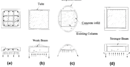
Figure 1 summarizes and schematically compares the four different transverse reinforcements. In a well-confined reinforced concrete column design based on modern seismic design provisions, as shown in Figure 1-a, hoops or spirals and cross ties are provided to contain the core concrete, particularly for the potential plastic hinge regions near the ends of a column. Spacing of the hoops and ties along the column and the intervals of the cross ties within the section are limited in order to achieve better efficiency of confinement. A similar confinement mechanism is achieved for retrofitted columns using the combined jacketing and through bolting method by Aboutaha et al. (1996). In a tubed column with a square or rectangular section, as shown in Figure 1-b, the weak out-of-plane stiffness results in poor confinement of portions of the concrete section. As exhibited in Figure 1-c, the use of an elliptical-shaped steel jacket for retrofit can provide a continuous transverse confinement to the existing concrete section. The partially stiffened rectilinear steel jacket developed in this study intends to rely on a beam action of the confinement elements (stiffeners) to develop efficient transverse confinement to the concrete section, as illustrated in Figure 1-d.
2.
Modelling And Analysis Of Building
2.1 Building Geometry
In the present work a 3-D structural model is used which comprises of G+9 storey reinforced concrete moment resisting frame. The foundation of the structure is assumed to be fixed. The data assumed for the analysis of building is shown in Table 1.
Table.1: The data assumed for the analysis of building.
Entity
Description
No of Bays in X
Direction
3
No of Bays in Y
Width of Bay in X
Direction
3 m
Width of Bay in Y
Direction
3 m
Storey Height
3 m
Live Load
3 kN/m
2Floor Finish
1 kN/m
2Concrete Grade
M20
Rebar
Fe415
Beam Size
250mm x 250mm
Column Size
300mm x 300mm
2.2 Material Properties
M-20 grade of concrete and Fe-415 grade of reinforcing steel are used for all the frame models used in this study. Elastic material properties of these materials are taken as per Indian Standard IS 456 (2000). The short-term modulus of elasticity (Ec) of concrete is taken as:
(1)
Where fck = characteristic compressive strength of concrete cube in MPa at 28-day (20 MPa in this case). For the steel rebar, yield stress (fy) and modulus of elasticity (Es) is taken as per IS 456 (2000).
Steel Jacket Modelling
The grade of steel used for jacketing of RC column is Fe250. The steel jacket used for retrofitting purpose is not provided over the full length of column but it only provided at possible hinge location. The jacket provided around the column should only undergo shearing action and should not participate in bending of column adding to additional strength of column. Xiao and Wu have suggested a retrofit design procedure was developed in order to provide additional confinement and shear strength to convert an existing deficient column to the condition satisfying current seismic design provisions. In the seismic design provisions of the current ACI 318 code (1999) to ensure the rotational deformability of the potential plastic hinges near column ends, the transverse reinforcement is specified as
(2)
(3)
Where, Ash = total transverse steel cross-sectional area within spacing s; hc= cross-sectional dimension of column core measured center-to-center of the outermost peripheral hoop, fc'= specified
compressive strength of concrete; fyh = specified yield strength of transverse reinforcement; Ag = gross area of section; and Ach =cross-sectional area of a column measured out-to-out of transverse reinforcement.
Behavior factor (R)
The behavior factor (R) is the ratio of the strength required to maintain the structure elastic to the inelastic design strength of the structure, Reza Akbari and Mahmoud R. Maheri (2001). In other words, it is a force reduction factor used to reduce the linear elastic response spectra to the inelastic response spectra. It is found through Push over analysis. The behavior factor, R, accounts for the inherent ductility, over strength of a structure and difference in the level of stresses considered in its design. FEMA (1997), UBC (1997) suggests the R factor in force-based seismic design procedures. It is generally expressed in the following form taking into account the above three components,
(5)
Where, Rμis the ductility dependent component also known as the ductility reduction factor, RSis the over-strength factor and Y is termed the allowable stress factor.
Linear Time History Analysis
Time-history analysis is a step-by-step analysis of the dynamical response (in time domain) of a structure subjected to a specified ground motion. The dynamic input has been given as a ground acceleration time-history which was applied uniformly at all the points of the base of the structure; only one horizontal component of the ground motion has been considered. Three natural ground acceleration time histories were employed for the dynamic analysis of the study.
popular due to its intrinsic stability.
(a)
(b)
(c)
Figure 2 Input Acceleration Time History (a) Imperial Valley (b) North ridge (c) Loma Prieta
Earthquake.
3.
Results And Discussion
3.1 Modal Time Period and Frequency
The time period of both bare frame and retrofitted building are calculated using modal analysis. The time period and frequency are analyzed in X, Y and torsional direction. Table 2 shows time period for bare frame and retrofitted building in X, Y and torsional direction for first, second, third and fourth mode of vibration
Table 2 - Modal Time Period of Bare Frame and Retrofitted building
Direction
Mode
No.
Time Period (sec)
Bare
Frame
Retrofitted
X
1
1.345
1.182
2
0.442
0.387
3
0.255
0.220
4
0.179
0.153
Y
1
1.345
1.181
2
0.442
0.387
3
0.255
0.220
4
0.179
0.153
Torsion
1
1.212
1.084
2
0.4
0.357
3
0.235
0.208
4
0.165
0.143
From Table 3 it can observed that modal time period for bare frame and retrofitted building is highest for first mode and reduces with increasing mode number in X, Y and torsional mode of vibration. Moreover it is also observed that modal time period in X and Y direction for first, second, third and fourth mode is same which clearly indicates that the building is symmetric in geometry. When the modal time period of bare frame structure and retrofitted building are compared in their respective mode and direction, the modal time period is found less in case of retrofitted building than bare frame building. This is the result of the increased stiffness which has occurred due to steel jacketing of the RCC column near the plastic hinge region.
3.2. Mode Shapes
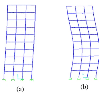
The mode shapes obtained for bare frame model are shown in Figure 3. Same type of mode shapes were obtained for retrofitted building model. Since the mode shape obtained in X and Y direction is similar therefore mode shape of X and torsional mode are only shown.
(c)
(d)
Figure 3 - Picture (a), (b), (c) and (d) represent first, second, third and fourth mode shape in X and Y directions.
3.3 Linear Time History Analysis
To study the response of building under real earthquake ground motions linear dynamic time history analysis is carried out. This analysis exhibits real earthquake effects and the responses obtained are very practical. Therefore the behavior of building with steel jacketing technique is studied under three acceleration time histories of different earthquake ground motions. Fig. 4 depicts storey displacement of bare frame and retrofitted building for three different acceleration time histories.
(a)
(b)
(c)
Figure 4- Storey Displacement for Bare Frame and Retrofitted Building for (a) Imperial Valley (b)
North Ridge and (c) Loma Prieta Earthquake Storey displacement increased with increasing number of storey in both building structure. But the comparative study of storey displacement for bare frame and retrofitted structure revealed that storey displacement decreased for retrofitted structure. This is the consequence of adding additional stiffness to the building column by steel jacketing technique.
Storey drift have damaging effect lateral load resisting element. Therefore comparative results of storey drift are framed for bare frame and retrofitted structure subjected to three ground motions.
(a)
(c)
Figure 5- Storey Drift for Bare Frame and Retrofitted Building for (a) Imperial Valley (b) North Ridge and (c) Loma Prieta Earthquake
From Figure 5 the maximum storey drift is observed at second floor and least at tenth storey in both building structure. The relative comparison of storey drift reveals that bare frame structures are susceptible to larger storey drift than retrofitted structure. The most obvious reason for such response is the increased lateral stiffness of column which decreased displacement at each storey thereby decreasing the storey drift.
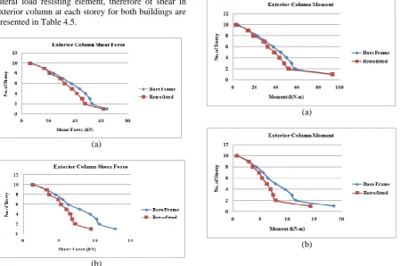
Lateral forces induced due to earthquake affect lateral load resisting element, therefore of shear in exterior column at each storey for both buildings are presented in Table 4.5.
(a)
(b)
(c)
Figure 6- Shear Force Distribution in Exterior Column of Bare Frame and Retrofitted Building for
(a) Imperial Valley (b) North Ridge and (c) Loma Prieta Earthquake
The observation from Figure 6 exhibit that first storey exterior column are subjected to highest amount of shear force and least for top storey column. Therefore lower storey columns are highly damaged and hence more attention is towards lower storey column while retrofitting. On comparing the shear between the bare frame and retrofitted structure reveals that it is less in case of retrofitted structure due to increased stiffness.
(a)
(c)
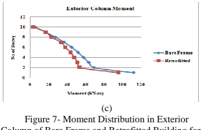
Figure 7- Moment Distribution in Exterior Column of Bare Frame and Retrofitted Building for
(a) Imperial Valley (b) North Ridge and (c) Loma Prieta Earthquake
It is evident from Figure 7 that retrofitting by steel jacketing technique had helped in reducing the moment in the entire storey column. Moment is maximum in lower storey column, reduces with increase in number of storey and is least in top storey column.
4.
Conclusion
Based on this analytical study following conclusion are drawn:
The fundamental time period is more for Bare Frame than Retrofitted building.
The displacement of Retrofitted building is (20 % - 40 %) less than bare frame.
Exterior column shear forces of Retrofitted building are (5 % - 20 %) less than bare frame.
Base shear of Retrofitted building with steel jacketing is more than the Bare Frame.
Inelastic capacity of Retrofitted building with steel jacketing is more than the Bare Frame.
The Retrofitted building performs well in earthquake than bare frame due to provision of steel jacketing.
5.
References
Vistasp M. Karbhari, Yanqiang Gao “Composite Jacketed Concrete Under Uniaxial Compression verification” Joumalof Materials in Civil Engineering, ASCE,Vol. 9. No.4, 1997, ISSN 0899-1561197/0004, pp. 0185-0193.
Jamie E. Padgett and Reginald Des Rochesb “Three-dimensional nonlinear seismic performance evaluation of retrofit measures for typical steel girder bridges” Engineering Structures, vol. 30, 2008, pp. 1869–1878.
R. Ma, Y. Xiao U, K.N. Li “Full-scale testing of a parking structure column retrofitted with carbon fiber reinforced composites” Construction and Building Materials, vol. 14, 2000, pp 63-71.
Joseph M. Bracci, Andrei M. Reinhorn and John B. Mander “Seismic Retrofit of Reinforced Concrete
Buildings Designed for Gravity Loads: Performance of Structural Model” ACI Structural Journal, vol. 92, No. 6, Nov-Dec 1995.
H. Saadatmanesh, M. R. Ehsani, and M. W. Li “Strength and Ductility of Concrete Columns Externally Reinforced with Fiber Composite Straps”ACI Structural Journal, V. 91, No. 4 July-August 1994.pp 434-447.
Y. Xiao , H. Wu and G. R. Martin, “Prefabricated Composite Jacketing Of Rc Columns For Enhanced Shear Strength” Journal of Structural Engineering, Vol. 125, No. 3, March, 1999. ASCE, ISSN 0733-9445, pp. 0255–0264
M. J. N. Priestley* and F. Seible , “Design of seismic retrofit measures for concrete and masonry structures” Construction and Building Materials, Vol. 9, No. 6, pp. 365-311, 1995
Mais M. Al-Dwaik and Nazzal S. Armouti, “Analytical Case Study of Seismic Performance of Retrofit Strategies for Reinforced Concrete Frames: Steel Bracing with Shear Links Versus Column Jacketing” Jordan Journal of Civil Engineering, Volume 7, No. 1, 2013.
Gnanasekaran Kaliyaperumal and Amlan Kumar Sengupta, “Seismic Retrofit Of Columns In Buildings For Flexure Using Concrete Jacket” ISET Journal of Earthquake Technology, Paper No. 505, Vol. 46, No. 2, June 2009, pp. 77–107.
Bhavar Dadasaheb O., Dhake Pravinchandra D. and Ogale Ramesh A, “Retrofitting of Existing RCC Buildings by Method of Jacketing ” International Journal of Research in Modern Engineering and Emerging Technology Vol. 1, Issue: 5, June: 2013 (IJRMEET) ISSN: 2320-6586.
Pranay Ranjan and Poonam Dhiman, “Retrofitting of Columns of an Existing Building by RC, FRP and SFRC Jacketing Techniques”, IOSR Journal of Mechanical and Civil Engineering (IOSR-JMCE) e-ISSN: 2278-1684, p-e-ISSN: 2320–334X, pp. 40-46.