N A N O E X P R E S S
Open Access
Simulation of forced convection in a channel with
nanofluid by the lattice Boltzmann method
Nor Azwadi Che Sidik
*, Maysam Khakbaz, Leila Jahanshaloo, Syahrullail Samion and Amer Nordin Darus
Abstract
This paper presents a numerical study of the thermal performance of fins mounted on the bottom wall of a horizontal channel and cooled with either pure water or an Al2O3-water nanofluid. The bottom wall of the channel is heated at a constant temperature and cooled by mixed convection of laminar flow at a relatively low
temperature. The results of the numerical simulation indicate that the heat transfer rate of fins is significantly affected by the Reynolds number (Re) and the thermal conductivity of the fins. The influence of the solid volume fraction on the increase of heat transfer is more noticeable at higher values of the Re.
Keywords:Nanofluid, Volume fraction, Nusselt number, Reynolds number, Lattice Boltzmann method
Background
Recent years have eyewitnessed a blossom flourishing in the evolvement of electronics, communications, and auto-computing industries, and this bearing is irrefutably con-tinuing in this century. The cooling of electrical, mechan-ical, and electronic components has become troublesome in today's fast-growing technologies. Inasmuch as the sig-nificance of heat exchangers in tremendous engineering applications, the subject of potential heat transfer enhance-ment in these devices has received sizeable attention in practice and research. On account of the fact that the consistency of the electronic components commodiously increases, conspicuous lack of heat transfer enhancement both in macro- and microscales of channels is realized. Encountering a fluid flow by utilizing transverse surfaces in a channel is a prevalent method that is used to intensify the rate of heat transfer from heated surfaces.
Alamyane and Mohamad [1] studied the forced convec-tion heat transfer in a channel with extended surfaces. The effects of the Reynolds number (Re) and the fin height and spacing on the fluid flow and the heat transfer were exam-ined. Yang et al. [2] simulated the forced convection in a parallel plate channel. Constant temperature was consid-ered in both upper and lower walls, and a transverse object was located at the lower channel wall. The effects of the Reynolds number, the thermal conductivity ratio of the
fluid, and the fin profile area on the fluid flow and the heat transfer rate were analyzed. The study results showed that the heat transfer enhancement with an increment of the Reynolds number and the thermal conductivity ratio of the fluid at various fin profiles. Yang et al. [3] numerically inves-tigated the effect of mix convection heat transfer in an inclined parallel plate channel with a transverse object at the bottom wall. In this research, the effects of thermal con-ductivity, Reynolds number, the fin profile, and the channel inclination on the heat transfer rate at various Richardson numbers were examined. They discovered that the ace aspect ratio of the fin was related to the fin with utmost heat transfer at various Reynolds and Richardson numbers.
Young and Vafai [4] observed the impact of controlling parameters on the cooling of heated channels with mounted objects. Concentrating on the effect of altering the dimensions of the object, the thermal conductivity, the heating method, and the Re was embraced. They deduced that the fluid flow and heat transfer are affected by the geometry and material of the object, and a correlation for the average Nusselt number was proposed as a function of the controlling parameters.
Meinders and Hanjalic [5] experimentally investigated the effect of the cubes' arrangement on the turbulent fluid flow. They comprehended that the flow stream was affected by the distance between the objects owing to the fact of augmenting the flow velocity. Moreover, amelioration in velocity distribution and heat transfer than the staggered distribution case was found for flow * Correspondence:[email protected]
Faculty of Mechanical Engineering, Universiti Teknologi Malaysia, UTM Skudai, Johor 81310, Malaysia
over inline cubes. Yan et al. [6] experimentally investigated the influence of short surface-mounted objects at the top of a flat plate on the heat transfer enhancement. Scrutinizing was done on the effect of varies cross sections, spacing and numbers of objects, and the Reynolds number. They perceived that the heat transfer was incremented when the height of the object is comparatively equal to half of the channel height.
In an experimental investigation by Yuan et al. [7], the heat transfer and friction characteristics of a channel which were attached by winglets were examined. Heat transfer from the channel was achieved to be noticeably augmented by using winglets in comparison with conven-tional channels with rectangular transverse objects. For a high Reynolds number, the heat transfer was enhanced by a factor of 2.7 to 6 times of the smooth channel.
Utilizing nanofluids for the purpose of enhancing the heat transfer in thermal systems is another alternative technique [8]. The thermal performance of different types of nanofluids has been the subject of many recent studies on forced, natural, and mixed convection problems. Several explorations have studied natural convection of nanofluids in cavities [9,10]. They argued that the addition of nanoparticles in the fluid indisputably increase the natural convection heat transfer.
Chein and Huang [11] analyzed the cooling of two silicon microchannel heat sinks with a water-Cu nanofluid. The heat transfer and fraction coefficients were based on the theoretical models and the experimental correlations. They realized that the heat transfer performance of microchannels was greatly improved when nanofluids were added into base fluid as coolants without any extra pressure drop.
Recently, Santra et al. [12] numerically investigated the effect of water-Cu nanofluid through parallel plate channel in laminar forced convection. A cold nanofluid was sent through the channel, and the walls of the channel were isothermally heated. The effects of the Reynolds number and the solid volume fraction on the heat transfer were studied by considering the fluid to be Newtonian and non-Newtonian. They observed that the rate of heat transfer increased with an increase of the Reynolds number and the solid volume fraction. The increase in the heat transfer was approximately the same for both scenarios.
The lattice Boltzmann method (LBM) is another numer-ical method that is often used to simulate flow problems. LBM have been used for more than 2 decades as an alter-native numerical technique. In LBM, it is intended to model fluids as a collection of particles, which successively undergo collision and propagation over a discrete lattice mesh. Several lattice Boltzmann models have been proposed for the incompressible Navier–Stokes equations. A collision model was proposed by Bhatnagar et al. [13] to simplify the analysis of the lattice Boltzmann equation, which leads to the so-called lattice BGK model. Remarkable efforts have been conducted by many researchers that made this numerical method more attractive for fluid dynamics modeling, e.g., [14,15]. For more details about LBM and its application, kindly refer to the aforementioned publications.
Most of the researches cited above considered the heat transfer enhancement by adding either the fin or using nanofluids. The main objective of this study is to examine both of these effects on the heat transfer performance. In general, previous works were performed to investigate dif-ferent cases of nanofluid flow and heat transfer in channels with mounted objects by focusing on changing geometries, arrangement, and dimensions of the objects. However, more efforts are needed in order to optimize the controlling parameters for best heat transfer enhancement.
Methods
Problem definition
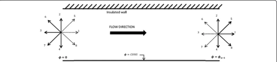
The geometry of the problem is shown in Figure 1. A cold mixture of base fluid (water) and the nanoparticles (alu-mina) is forced to flow into a channel that is heated from its bottom and kept at a constant high temperature, while the top wall is insulated. The channel aspect ratio is fixed at L/ H = 15. The Prandtl number is taken as 7.02, and the Reyn-olds numbers are 10, 50, and 100, whereas the extended surfaces' height to space ratio l/S is 0.2, and the ratio be-tween the objects' height to the channel's height l/H is 0.2.
[image:2.595.58.539.621.714.2]The flow is assumed as Newtonian, laminar, two-dimensional, and incompressible. In addition, it is assumed that the cold mixture of base fluid (water) and the solid spherical nanoparticles (alumina) is in thermal equilibrium, and it flows at the same velocity as a homogenous mixture.
Numerical simulation
The D2Q9 LBM model is used to simulate fluid flow in two-dimensional channel with uniform grid size ofδx×δy. The lattice Boltzmann equation (known as LBGK equation) with single relaxation time can be expressed as [13]
fiðxþeiΔt;tþΔtÞ fiðx;tÞ ¼
1 τf
fifieq
ð1Þ
which can be reformulated as
fiðxþeiΔt;tþΔtÞ ¼ωffieqþ 1ωf
fi ð2Þ
where ωf ¼τ1f and τfas the single relaxation time of the
fluid,firepresents the particle distribution function,eiis the
particle streaming velocity, and fieq is the local equilibrium distribution function. For D2Q9 modelfieqis given by [8]
fieq ¼ρωi 1þ3ei⋅uþ
9 2ðei⋅uÞ
23
2u
2
ð3Þ
where ρ is the density of the fluid and ωi is the weight
function, which has the values of ω0¼49, ωi¼19 fori= 1
to 4, andωi¼361 fori= 5 to 8. The macroscopic fluid flow
velocity in lattice units is represented by u. In the LBM, the fluid macroscopic quantities such as density, ρ, and flow momentum,ρu are calculated using the distribution
functionfi, and given byρ¼ X8
i¼0
fiand ρu¼X
8
i¼0
eifi,
res-pectively. The streaming speed for particles in coordinate (x and y) directions (i.e., 1 to 4, see Figure 2) can be expressed asei= cos(π/2 (i−1)), sin(π/2 (i−1)), whereas particles in diagonal directions (i.e., 5 to 8 in Figure 2) have velocities of ei¼
ffiffiffi 2
p
cosðπ=4 2ið 9ÞÞ;sinðπ=4 2ið 9ÞÞ
ð Þ;
however, the particle in the lattice center is at rest and has no streaming speed, i.e.,e0= 0.
The thermal part is simulated using another distribu-tion funcdistribu-tion for the temperature. For instance,gis used to simulate the distribution function of the dependent variable (temperature) in the lattice Boltzmann equation, and an approach similar to that used to simulate the fluid flow is utilized to simulate the temperature
distribution. In addition, the algorithm suggested by Succi [15] is adopted throughout this work. The kinetic equation for the temperature distribution function with single relaxation time is given by:
giðxþeiΔt;tþΔtÞ giðx;tÞ ¼
1 τt
gigieq
ð4Þ
which can be written in the form
giðxþeiΔt;tþΔtÞ ¼ωtgeqi þ½1ωtgi ð5Þ
Wheregirepresents the temperature distribution
func-tion of the particles,gieq is the local equilibrium distribu-tion funcdistribu-tion of the temperature, andωt¼τ1t, whereτtis
the single relaxation time of the temperature distribu-tion. Thus, the equilibrium distribution function of the thermal part is given by [15]:
gieq¼ϕðx;tÞωi 1þei⋅u
C2
s
ð6Þ
where, ϕ is the macroscopic temperature and C2
s is the
speed of sound. The diffusion coefficient can be obtained as a function of the relaxation time and given byΔΔxt21ω12 . The macroscopic temperature is then computed from:
ϕðx;tÞ ¼X
8
i¼0
gi¼
X8
i¼0
gieq ð7Þ
A uniform lattice of 100 × 1,500 is used to perform all of the simulations. However, the number of lattices was doubled to test the grid dependency results.
Since the inlet velocity of the flow is specified, the inward distribution functions should be computed at the boundary. In the D2Q9 model, the values of the distri-bution functions pointing out of the domain at the inlet boundary (i.e., f3, f6,f7in Figure 2) are known from the streaming step, and the only unknowns are (f1, f5, f8) as well as the fluid density ρ. Following the work of Zou and He [16], the inlet density and the distribution functions can be obtained from:
ρin¼
1 1uin
f0þf2þf4þ2ðf3þf6þf7Þ
[image:3.595.59.539.605.714.2]½ ð8Þ
The unknown distribution functions are calculated using
f1¼f3þ
2 3ρux
f5¼f7
1
2ðf2f4Þ þ 1 6ρuxþ
1 2ρuy
f8¼f6þ
1
2ðf2f4Þ þ 1 6ρuxþ
1 2ρuy
ð9Þ
An extrapolation scheme is used to simulate the outlet flow condition, which can be represented asfi(Nx, t) = fi
(Nx−1,t), i= 3, 6, 7. The bounce-back scheme is used
to specify the boundary conditions on solid surfaces (no-slip boundary), in which the distribution functions pointing to the fluid are equal to those pointing out of the domain. The thermal boundary conditions for this case are given in Figure 2. For constant wall temperature (the lower wall temperature is constant), the unknown functions are obtained using the following equation [15]:
gi¼ϕwallðωiþωiþ2Þ giþ2fori¼2;5 and 6 ð10Þ
The left-hand boundary (channel inlet) is kept at a con-stant temperature (Dirichlet boundary condition) and set to a dimensionless value of zero. Therefore, the resulted equations of the unknown distribution functions on the left boundary are given by gi(0,t) = −gi + 2(0,t), fori= 1, 5, and 8. For the adiabatic boundary condition, the gradient of the dependent variable normal to the boundary should be zero, i.e., ∂ ϕ/∂ y = 0. The distribution functions are found to be in the following form [15]:
X8
i¼0
gi x;Nyþ1
¼X
8
i¼0
gi x;Ny
ð11Þ
A second-order extrapolation similar to the one given in [17] is used to obtain the values of the unknown dis-tribution functions for the right-hand side boundary (channel outlet) as follows:
giðNx;tÞ ¼2giðNx1;tÞ giðNx2;tÞfori
¼3;6;and 7: ð12Þ
The local Nusselt number (Nux) is computed using the
following equation:
Nux¼
LCð∂ϕ=∂yÞy¼0
ϕwallϕm
ð13Þ
whereLcis the characteristic length andϕwallis the wall
constant temperature. The mean temperature ϕm is
given by:
ϕm¼
Z uϕdA Z
udA
ð14Þ
The effective density of the nanofluid is
ρnf ¼ð1φÞρf þφρs ð15Þ
where ϕ is the solid volume fraction. The effective
[image:4.595.62.539.495.718.2]dynamic viscosity of the nanofluid given by Brinkman [18] is
μnf ¼ μf
1φ
ð Þ2:5 ð16Þ
The thermal diffusivity of the nanofluid is
αnf ¼
keff ρcp
nf
ð17Þ
The heat capacitance of the nanofluid is ρcp
nf ¼ð1φÞ ρcp
fþ ρcp
s ð18Þ
keffis the effective thermal conductivity of the nanofluid
and is determined using the model proposed by Patel et al. [19]. For the two-component entity of spherical particle suspension, the model gives:
keff ¼kf 1þ
ksAs
kfAf þ
cksPe
As
kfAf
ð19Þ
where ks and kf are the thermal conductivities of
dispersed Al2O3nanoparticles and pure water.
Pe¼usds
αf ð
20Þ
where us is the Brownian motion velocity of the
nanoparticles given by:
us¼
2kbT πμfds2
ð21Þ
[image:5.595.55.543.92.465.2]wherekb= 1.3087×10⁻²³JK−1is the Boltzmann constant.
[image:5.595.56.546.538.719.2]Figure 5Velocity and temperature profiles at different Re.
Results and discussion
Code validation and computational results
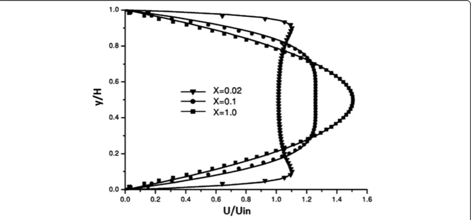
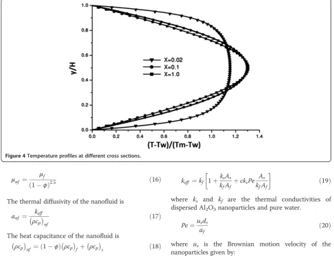
For the purpose to ensure that the obtained results are proper and that the code is free of errors, a flow of cold air in a two-dimensional heated channel was taken as a benchmark test. Both upper and lower walls were heated. The comparisons were carried up between the dimensionless velocity and temperature fields at different
locations in the channel as shown in Figures 3 and 4. The obtained results were found to be identical to the results of [20].
[image:6.595.58.539.87.583.2]Figure 5 shows the effect of Reynolds on the temperature profiles at the same cross sections for Re = 10, 50, and 100. The figures depicted that the temperature profiles are less sensitive to the change in Reynolds compared to the velocity profiles.
Figure 6Streamlines and isotherms for the Al2O3-water nanofluid and pure water at different Reynolds number.(A) Streamline plots at
The effects of the Reynolds number and the solid volume fraction on the heat transfer, isotherms, and streamlines are studied. Figure 6 presents the stream-lines and the isotherms for the Al2O3-water nanofluid (ϕ = 0.05) and pure water at different Reynolds number (Re = 10, 50, and 100).
The streamlines show that as the Reynolds number increases, the vortices that are formed behind the fins become larger and stronger. This can be more clearly illustrated in Figure 5 where the horizontal velocity in the middle section between fins is presented. At Re = 10, the velocity is consistently positive. However, as the Reynolds number increases, the flow velocity becomes negative. This is an indication of flow reversal. The strong vortex at high numbers enhances the heat transfer from left face objects to right face objects and the wall between the two fins. This difference, however, becomes noticeable at higher Re.
At low Reynolds numbers, the conduction is the dominating mechanism of heat transfer. Therefore, the isotherms stretch above the fins and take a large area in the channel. As Re increases, the convection becomes the dominating mechanism, and the strong cold inlet flow pushes the isotherms near the bottom wall. The comparison between the isotherms of the nanofluid and pure water shows that in each point of the channel, the nanofluid temperature is higher than the pure water. It is due to the nanofluid's higher thermal conductivity.
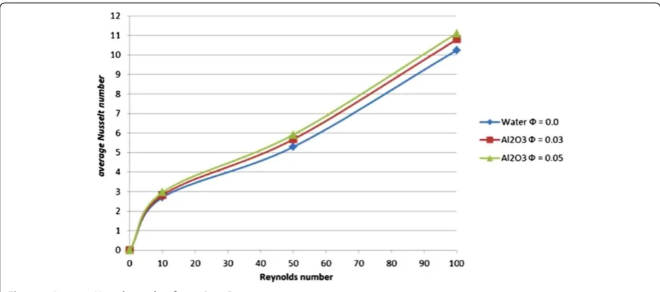
The current investigation is wrapped with the analysis of the effect of the Reynolds number and percentage of nanoparticle volume fraction on the heat transfer enhancement in the channel. Figure 7 and Table 1 display values of average Nusselt number at various
Reynolds numbers and solid volume fraction from 0% to 5%. These figures demonstrate that the Nusselt number increases with the Reynolds number for values of volume fraction tested in the present study. For example, at Re = 100, in the addition of volume fraction of 5%, the average Nusselt number increases about 17%. High Reynolds number results in high energy transport through the fluid and cause irregular motion of nanoparticle. The higher solid volume fraction further stimulates the flow and contributes to higher Nusselt number as shown in the figure. The presence of nanoparticles also increases the rate of heat transfer by conduction mode through the flow.
Conclusions
[image:7.595.57.538.88.301.2]LBM was applied to simulate forced convection heat transfer in two-dimensional channel including extended surfaces to investigate the effect of changing different parameters such as Reynolds number (10, 50, and 100) and nanofluid (Al2O3) volume fractions (0.0, 0.03, and 0.05). The results showed that as the Reynolds number increases, the rate of heat transfer also increases. The formation of vortices both in front and behind the objects enhances the heat transfer process. As the solid volume fraction increases, the heat transfer is enhanced
Table 1 Average Nusselt number for various Reynolds number and solid volume fraction
Reynolds number
Average Nusselt number ϕ
= 0.0 ϕ= 0.03 ϕ= 0.05
Re = 10 Nuave 2.712 2.826 2.965
Re = 50 Nuave 5.294 5.683 5.919
[image:7.595.306.540.668.733.2]Re = 100 Nuave 10.252 10.797 11.109
for all values of the Reynolds numbers. This enhance-ment is more significant at high Reynolds numbers. The heat transfer rate of the fins increases with the thermal conductivity ratio of the fin to pure water. This enhance-ment has a finite limit. At this limit, the temperature at all surfaces of the fins approach the wall temperature. In this condition, the fins behave like constant temperature of heat sources.
Competing interests
The authors declare that they have no competing interests.
Authors’contributions
MK, LJ, and SS conceived the study and checked the grammar of the manuscript. NACS and AND drafted the manuscript. All authors read and approved the final manuscript.
Acknowledgments
This research is financially supported by the Ministry of Higher Education of Malaysia through Fundamental Research Grant Scheme, FRGS Vot no. 4L074.
Received: 11 February 2013 Accepted: 29 March 2013 Published: 17 April 2013
References
1. Alamyane AA, Mohamad AA:Simulation of forced convection in a channel with extended surfaces by the lattice Boltzmann method.
Comput Math Appl2010,59:2421–2430.
2. Yang MH, Yeh RH, Hwang JJ:Forced convective cooling of a fin in a channel.Energy Convers Manage2010,51:1277–1286.
3. Yang MH, Yeh RH, Hwang JJ:Mixed convective cooling of a fin in a channel.Int J Heat Mass Transfer2010,53:760–771.
4. Young TJ, Vafai K:Convective cooling of a heated obstacle in a channel.
Int J Heat Mass Transfer1998,41:3131–3148.
5. Meinders ER, Hanjalic K:Experimental study of the convective heat transfer from inline and staggered configuration of two wall-mounted cubes.Int J Heat Mass Transfer2002,45:465–482.
6. Yan WM, Hsieh RC, Soong CY:Experimental study of surface-mounted obstacle effects on heat transfer enhancement by using transient liquid crystal thermograph.J Heat Transfer2002,124:762–769.
7. Yuan ZX, Tao WQ, Yan XT:Experimental study on heat transfer in ducts with winglet disturbances.Heat Transfer Eng2003,24:76–84.
8. Fakhreddine SO, Rachid B:Heterogeneous nanofluids: natural convection heat transfer enhancement.Nanoscale Res Lett2011,6:222–232. 9. Veeranna S, Lakshmi NS:AL2O3-based nanofluids: a review.Nanoscale Res
Lett2011,6:456–471.
10. Saeed ZH, Seyyed HN, Elham T, Javad S:Numerical investigation of Al2O3/
water nanofluid laminar convective heat transfer through triangular ducts.Nanoscale Res Lett2011,6:179–188.
11. Chein R, Huang G:Analysis of microchannel heat sink performance using nanofluids.Appl Therm Eng2005,25:3104–3114.
12. Santra AK, Sen S, Chakraborty N:Study of heat transfer due to laminar flow of copperewater nanofluid through two isothermally heated parallel plates.Int J Therm Sci2009,48:391–400.
13. Bhatnagar PL, Gross EP, Krook M:A model for collision processes in gases. I. Small amplitude processes in charged and neutral one-component systems.Phys Rev1954,94:511–525.
14. Peter V:Heat transfer augmentation in nanofluids via nanofins.Nanoscale Res Lett2011,6:154–166.
15. Succi S:Applied lattice Boltzmann method for transport phenomena, momentum, heat and mass transfer.Can J Chem Eng2007,85:946–947. 16. Zou Q, He X:On pressure and velocity boundary conditions for the
lattice Boltzmann BGK model.Phys Fluids1997,9:1591–1598. 17. He Y, Qi C, Hu Y, Qin B, Li F, Ding Y:Lattice Boltzmann simulation of
alumina-water nanofluid in a square cavity.Nanoscale Res Lett2011, 6:184–191.
18. Brinkman HC:The viscosity of concentrated suspensions and solution.
J Chem Phys1952,20:571–581.
19. Patel HE, Sundararajan T, Pradeep T, Dasgupta A, Dasgupta N, Das SK: A micro-convection model for thermal conductivity of nanofluids.
Pramana J Phys2005,65:863–869.
20. Kays WM, Crawford ME, Weigand B:Convective Heat and Mass Transfer.
4th edition. Boston: McGraw Hill; 2005.
doi:10.1186/1556-276X-8-178
Cite this article as:Sidiket al.:Simulation of forced convection in a
channel with nanofluid by the lattice Boltzmann method.Nanoscale Research Letters20138:178.
Submit your manuscript to a
journal and benefi t from:
7Convenient online submission
7Rigorous peer review
7Immediate publication on acceptance
7Open access: articles freely available online
7High visibility within the fi eld
7Retaining the copyright to your article