www.ijsrp.org
An Efficient Majority Logic Fault Detection to reduce the
Accessing time for Memory Applications
R.Meenaakshi Sundhari
1, C.Sundarrasu
2, M.Karthikkumar
3 Department of Electronics and Communication Engineering,Sasurie College of Engineering
Abstract:Even a small transition delays and little faults create major concern in digital circuits. It Produce greater impact on not only for simple memory but also for most of the memory applications. So, the majority logic decoders implemented with quasi cyclic LDPC codes are used to correct those problems in a digital circuit. In this technique majority logic decoder is used as fault detector due to usage of quasi cyclic LDPC codes the number of taps N can be reduced in the decoder to get minimum accessing time and lower area overhead.
Index Terms:Error correction codes (ECCs), Block codes, low-density parity check (LDPC), memory, majority logic, Quasi Cyclic Codes.
I. INTRODUCTION
he reliability of memories depends on dimensions of the circuit, operating voltages, and integrated density Triple modular redundancy codes and error correcting codes are mostly used for error correcting. In those techniques a majority vote has been used to gives the perfect output and triggering the error correcting mechanism respectively. But they have high power consumption due to the voter circuit and it requires large area. Generally there is single bit error, double bit errors and multiple bit error detections codes are normally present in digital circuits. The decoding and encoding are so flexible in those types of codes. The consequence of augmenting integration densities, it increases the number of soft errors, which needs higher error correction capabilities.
Some multi error bit corrections Codes are reed Solomon codes and Bose- Chaudhuri- Hocquenghem codes, but in which the algorithm is so complex and it is iteration based. The decoders too decode in fixed rate and so it reduces the operating criteria. To attain higher capability to detect errors among error correcting codes the sub group of low density parity check code called quasi cyclic LDPC codes has been selected to increase the performance of the decoders to detect and correct large number of errors. It belongs to family of majority logic decoding.
The reason for using ML decoding is that it is very simple to implement and very practical and has low complexity. The parallel encoders and decoders have been implemented to overcome the drawback of majority logic decoder in which it takes N number of cycles to decode.
Figure 1: General Memory System
The parallel encoders and decoders have been implemented to overcome the drawback of majority logic decoder in which it takes N number of cycles to detect. In this paper we are detecting error in memory device itself so the data corruption during processing has been eliminated easily to give improved performance. The general memory system implemented with majority logic decoder as shown in the figure 1.
II. EXISTING OUTCOMES FROM MAJORITY LOGIC DECODER (EXISTING SYSTEM)
www.ijsrp.org Reed-Muller codes were the first mentioned by majority logic decoder. Then, it was extended and generalized in for all types of systematic linear block codes that can b e t o t a l l y orthogonal zed o n each codeword bit. Initially, the data words are encoded and then stored i n the memory. When t h e memory is read, the codeword is then fed through the majority logic decoder before sent to the output for further processing. In this decoding process, the data word is corrected from all bit-flips that it might have suffered while being stored in the memory.
There a r e t w o t y p e s o f i m p l e m e n t i n g majority l o g i c d e c o d e r . The first type is called the Type-I majority logic decoder, which determines, XOR combinations of the syndrome, which bits need to be corrected. Another type is the Type-II majority logic decoder that calculates directly out of the given codeword bits the information of correctness of the current bit under decoding. Both are similar but when it required for implementation, Type-II uses less area, as it does not calculate the syndrome as an in between steps.
A. Type I Majority Logic Decoder (plain majority logic decoder)
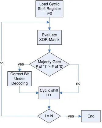
The majority logic decoder is a simple and powerful d e c o d e r , c a p a b l e o f c o r r e c t i n g multiple random bit flips depending on the number of parity check equations. It consists of cyclic shift register, XOR matrix, majority gate and XOR for correcting the codeword bit under decoding as shown in figure 2. The input is initially stored in the cyclic shift register and shifted through all the blocks. The intermediate values in each block are used to calculate the output results of the check sum equations from the XOR matrix. The result h a s r e a c h e d t h e f i n a l block, producing t h e f i n a l o u t p u t . Input may correspond to wr o ng d a ta corrupted by a soft error. After the initial step, in that the codeword is loaded into the cyclic shift register, the decoder starts by calculating the parity check equations executed in the XOR matrix.
Figure 2: Majority logic decoder system.
If the number of 1’s received in is greater than the number of 0’s that means the current bit under decoding is wrong, and a signal to correct it would be triggered. Else the bit under decoding i s correct and no extra operations would be needed o n it. In next, the content of the registers are rotated and the above procedure is repeated until codeword bits have been processed. Finally, the parity check sums should be zero if the codeword has been correctly decoded.
B. Type II Majority Logic Decoder ( with syndrome fault Detector)
To i mpr o ve t h e d e c o d e r p e r f o r m a n c e , various designs has been used. One possible way is to add fault detector by calculating its syndrome, so only faulty code words are decoded. But most of the code words will be error free initially, so no further correction is needed, therefore performance is not varied is disturbed. As well as the implementation of a syndrome fault detector reduces the average latency of the decoding and it also adds complexity to the design.
The syndrome fault detector is an XOR matrix that calculates the syndrome based on the parity check matrix. Each parity bit gives output as a syndrome equation. Thus, the complexity of the syndrome calculator increases with the size of the
code. A faulty codeword is detected when at least one of the syndrome bits is „1. This triggers the majority logic decoder to start the decoding. If the codeword is error free, it is forwarded directly to the output, thus saving the correction cycles.
www.ijsrp.org gates to resolve the parity check matrix, where each check bit results into a syndrome equation. This finally outputs in a complex module, with a large amount of additional hardware and power consumption in the system.
Figure 3: Flow Chart of Existing System
III. MAJORITY LOGIC DETECTOR/DECODER (PROPOSED SYSTEM)
The proposed majority logic decoder, in which the majority logic decoder itself act as a fault detector by implementing q u a s i cyclic LDPC codes in it. The LDPC codes which satisfies higher error correction capability due to its advanced properties.
Some important properties of cyclic codes are ability to correct more number of errors, easy to implements and very flexible algorithm systematic s t r u c t u r e f o r c l e a n partition of information bits and code bits in the memory. The cyclic codes are a systematical, distribution that a l l o w s t h e majority l o g i c decoder t o p e r f o r m e r r o r detection in a simple way by using parity check sums.
Whenever a data is read from the memory it is protected by q u a s i cyclic codes in majority logic decoder and which can able to detect up to five bit flips in three decoding cycles, which is the main advantage of proposed majority logic decoder.
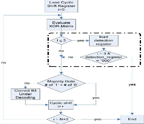
Generally, the decoding algorithm is still the same as the one in the Type I majority logic decoder version. The main difference is that, instead of decoding all codeword bits by processing during cycles, the proposed method stops intermediately in the third cycle, so the number of decoding cycles can be reduced to get increased performance. If the
first three cycles process and if it detects there is no error means then it gives direct output.
[image:3.612.126.511.517.679.2]
www.ijsrp.org Figure 5: Flow Diagram of the Proposed System
Else, it goes with further decoding cycles with respect to the number of code words implemented which is shown in flowchart as below in figure 5.The proposed system in which a control unit has been implemented to control the tri-state buffers that store temporary data until the three cycles have to complete in the process.
The above equations have been used to find the performance of the circuit, where N number of code words, M number of bit flips occurred.
Table I: Quasi Cyclic L D P C code Length
The above table shows the possible combinations of cyclic LDPC codes.
IV. RESULTS A. Area
Thus when compared to the existing system the number of decoding cycles has been minimized in the proposed system so it greatly reduces the area as well as power consumption. The syndrome fault detector version, which had the best performance, requires more area than the majority logic decoder does, ranging from 2 5 . 4 0 % t o 294.94% depending on N . I t s h o u l d b e n o t e d that t h e i n c r e me n t of area grows quicker than N does.
B. Read access delay and performance
[image:4.612.243.363.468.520.2]www.ijsrp.org Table II: Speed Up Performance of the Existing and Proposed System
N
Type I
Type II
Speed up
73
75
5
15
273
275
5
55
1057
1059
5
211.8
V. CONCLUSION
In this work, a fault detection technique, majority logic detector and decoder, has been presented based on majority logic decoding using the quasi cyclic LDP C codes. Exhaustive simulation test output shows that the proposed system is able to detect any pattern of up to five bit-flips in the first three cycles of the decoding, which improves the performance of the design with respect to the traditional majority logic decoding approach. In the same way, the majority logic detector and decoder in which error detector module has been proposed in a way that is independent of the code size. This makes its area overhead quite reduced compared with other traditional approaches such as the syndrome fault calculation.
REFERENCES
[1] Hao Zhong, Tong Zhong, Erich F. Haratsch “Quasi-Cyclic LDPC Codes for the Magnetic Recording Channel: Code Design and VLSI Implementation”. IEEE transactions on magnetics, vol. 43, no. 3, march 2007
[2] Marc P. C. Fossorier, Senior Member, IEEE “ Quasi-Cyclic Low-Density Parity-Check Codes From Circulant Permutation Matrices.” IEEE transactions on information theory, vol. 50, no. 8, august 2004
[3] R. G. Gallager, “Low density parity check codes,” IRE Trans. Inform Theory, IT-8, pp. 21-28, Jan. 1962. [4] S. Lin and D. J. Costello, Error Control Coding, 2nd Ed. Englewood Cliffs, NJ: Prentice-Hall, 2004.
[5] I. S. Reed, “A class of multiple-error- correcting codes and the decoding scheme,” IRE Trans. Inf. Theory, vol. IT-4, pp. 38–49, 1954. [6] J. L. Massey, Threshold Decoding. Cambridge, MA: MIT Press, 1963.
[7] S. Ghosh and P.D.Lincoln, “Low-density parity check codes for error correction in nanoscale memory,” SRI Comput. Sci. Lab. Tech. Rep. CSL-0703, 2007
AUTHORS
First Author- R. Meenaakshi Sundhari, Ph.D, Head of the Department, Sasurie College of Engineering, [email protected].
Second Author- C. Sundarrasu, M.E, Assistant Professor, Sasurie college of Engineering,[email protected]. Third Author- M. Karthikkumar, PG Scholar, Sasurie college of Engineering,[email protected].