ISSN: 1992-8645 www.jatit.org E-ISSN: 1817-3195
WIRELESS FAULT TOLERANCES DECISION USING
ARTIFICIAL INTELLIGENCE TECHNIQUE
1,2
MONEER ALI LILO *,1L.A.LATIFF, 3AMINUDIN BIN HAJI ABU, 4 YOUSIF I. AL MASHHADANY
1
Razak School of Engineering and Advanced Technology, Universiti Teknologi Malaysia, Kuala Lumpur
Malaysia.
2
College of Science, department of physics, Al Muthana University, Iraq.
3
Malaysia - Japan International Institute of Technology, Universiti Teknologi Malaysia. Kuala Lumpur,
Malaysia.
4
Engineering Department, Engineering College, University of Anbar, Iraq.
ABSTRACT
Wireless techniques utilized in industrial applications face significant challenges in preventing noise, collision, and data fusion, particularly when wireless sensors are used to identify and classify fault in real time for protection. This study will focus on the design of integrated wireless fault diagnosis system, which is protecting the induction motor (IM) from the vibration via decrease the speed. The filtering, signal processing, and Artificial Intelligent (AI) techniques are applied to improve the reliability and flexibility to prevent vibration increases on the IM. Wireless sensors of speed and vibration and card decision are designed based on the wireless application via the C++ related to the microcontroller, also, MATLAB coding was utilized to design the signal processing and the AI steps. The system was successful to identify the misalignment fault and dropping the speed when vibrations rising for preventing the damage may be happen on the IM. The vibration value reduced via the system producing response signal proportional with fault values based on modify the main speed signal to dropping the speed of IM.
Keywords: Industrial Wireless Sensor, Artificial Intelligent Technique, Signals Processing, Fault Diagnosis System.
1. INTRODUCTION
An IM with high or low speed is an important device in industrial applications. Certain applications utilize the IM as a driver of mechanical
systems. However, vibrations may spread
throughout the system and subsequently degrade the system. Therefore, engineers aim to prevent these faults and monitor the corresponding conditions [1]. Vibration is the root cause of many problems. However, vibration is a neutral phenomenon that is related to routing and stable systems. Moreover, vibration is also proportional to the speed and force applied on the machine , thus can protect the machine via reducing the speed or the force generation from load[2]. Most protection studies have a similar goal, which is to protect the system from harm in high vibration conditions or prior to the introduction of vibration to the
machine. A protection system will reduce
maintenance costs and operation times.
Displacement, velocity, and acceleration sensors are based on the measurements of the speed and vibration of the system [3].
Recently, industrial wireless sensor
ISSN: 1992-8645 www.jatit.org E-ISSN: 1817-3195
classifying the condition monitoring and control system whenever a fault occurs[6]. Moreover, the accuracy of a decision is based on the error produced from the comparative threshold limited by the design [7]. The accuracy of the decision system with fault diagnosis was increased by adding the fuzzy technique to the NN, resulting in an intelligent technique called “neural–fuzzy,” which is extensively utilized in AI applications [8][9]. Indeed, AI was used because of its ability and capability to identify and classify data gathered from the sensor with noise value. However, AI is also convenient for industrial application because most of the signals collected from the noise field continent are of different types[10].
Fuzzy fusion or fuzzy technique was
utilized to analyze machine behaviors by
comparing the saved situation with the collected data in real time. However, a system in danger can be protected from vibrations, depending on the technique [11][12]. Indeed, many researchers focused on transferring collected data via the wireless sensor to the central computer for classifying or analyzing data based on the wireless network technique[14][15]. some researchers used the IEEE standard for industrial and greenhouse applications[16][17], or the ISA100 standard [18]. [19] proposed a new method, which utilized a wireless sensor, to protect the wind turbine from vibration based on the classification of vibration into three zones; thus, their work predicts vibration in the danger zone. [20] designed a micro-electro- mechanical system accelerometer sensor that has the ability to sense frequency and low-amplitude acceleration. The proposed technique converts the outcome of the sensor from voltage to frequency values instead of transferring data from analog to digital values. Data conversion to frequency was conducted prior to transmission to the wireless item. However, data conversion to frequency increases the sensitivity and accuracy of the data being collected. This work is limited by errors, wireless protocol, and operating range. [3] proposed a new system of measuring the “acceleration” of vibrations using android devices linked via Bluetooth. Data were analyzed in the database server and delivered to the portable box to control another system. [21] presented a control system based on the wireless network technique. The main objectives of their work are to derive the feedback signal to the chief control system with high reliability and to prolong the real response time based on the wireless technique. Vibration data were collected from the beam and sent to the
control system for analysis, where the feedback signal was used to control the vibration of the beam.
AI techniques are extensively utilized to classify and identify the signal situation in a time series or in a frequency domain based on the monitoring conditions and operation limitations of a machine [22] [23][24]. [25] proposed a new type of plate form for the classification of bearing faults of the IM based on two stages of the NN. The generalized Hebbian algorithm and a supervised learning vector quantization network were algorithms of the NN used in this work. Moreover, the design of the wireless sensor was intended to collect vibration data from the indentation motor. [26] embedded the data acquisition system to optimize the dynamic NN and improve the prediction process and the accuracy of fault diagnosis. They gathered data from smart wireless sensors related to vibration and temperature and compared the two types of NN based on a dynamic NN and a nonlinear autoregressive neural system. However, they did not determine the processing time and control response based on the collected and displaced results.
ISSN: 1992-8645 www.jatit.org E-ISSN: 1817-3195
cannot predict the damage or problem related to the bearing of the mechanical system.
This study aims to design an integrated wireless fault diagnosis system that is utilized to protect the induction motor from the vibration phenomenon via reduce the speed or shutdown the system. Moreover, real time fault detection is based
on the neural–sleep–fuzzy technique. The
remainder of this paper is organized as follows: Section II presents the related works. Section III describes the architectural and methodological design. Section VI presents the results of the experiments. Section V concludes this work.
2. METHODOLOGY
The approach completed via two main programs, the first one is related to the MATLAB coding, which is implemented the filtering, signal processing, neural and the fuzzy. The other program that it is related to C++ of the MC, which is utilized to implemented the wireless vibration sensor, wireless speed sensor, and the decision card that used to feed the final signal to the speed controller. Furthermore, the system integrated to diagnosis the vibration fault to produce signal proportional with vibration to protect the IM that fault.
3. ARCHITECTURAL AND WORK DESIGN
The system has been design to represented integrated fault diagnosis system, the pressing steps in showed in the finger 2.a, the detail of all the steps depicted as flow.
3.1 Wireless sensor design and the prototype
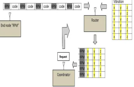
Data were collected using two wireless sensors and one coordinator connected to the central computer. These two sensors are the wireless vibration sensor WVS, which is utilized to collect vibration to the three axes from sample based on; the ATmega328 microcontroller, the acceleration sensor, the ZigBee based on the IEEE802.15.4 PHY and MAC layers, and lithium battery. Another wireless sensor that measures the speed of the IM has architecture similar to WVS. Seems, speed sensor has a magnetic field sensor instead of the acceleration part in WVS. The wireless network is shown in Figure 1, WVS is router, the speed sensor is represented the end nod in network. Actually, inside the vibration sensor the packet is preparing to contain the RPM, x , y, and z, which is send to coordinator, after the router receives request from the computer, the packet is
[image:3.612.317.537.134.278.2]saving in computer to processing, as shown in Figure 2.a.
Figure 1: Represented the data fusion in the wireless sensors network
A. Architectural Of The System
B. Architectural Of The Decision Card
Figure 2: Architectural Of System And The Decision Card
3.2 Processing signal and AI
[image:3.612.318.519.316.636.2]ISSN: 1992-8645 www.jatit.org E-ISSN: 1817-3195
the data must be filtered to reduce the noise amplitude based on the low pass filter (LPF) and band pass filter (BPF). Then, the vibration signals obtained from filtering were inputted into the fast Fourier transform (FFT) algorithm, which transfers the vibration to a frequency domain. Finally, the data will be input into the neural and the fuzzy system to identify and classify the situation of vibration on a machine. Researchers predominantly designed NN based on one stage or multiple stages. Furthermore, if the NN’s contains more than one stage, the designer places one of them in continuous operations, whereas the other stage are placed in sleep mode, the multi-stages of NN utilized to augment the classification accuracy [8][30]. In this study proposed a new technique called the neural– sleep–fuzzy. This technique depended on the result of the error backpropagation algorithm will wake up the Sugeno fuzzy part, if the vibrations occurred in the severity or alarm zone. Actually, the fuzzy system was used to add the speed signal with vibration values to apply the condition monitoring for protecting the machine from rise vibrations. The essence and utility of the utilized NN are to classify the vibration level. Moreover, the fuzzy system will add the speed value effective for generating signal that it is protecting the IM from vibration fault; the flow chart of this work is shown in Figure 3.
3.3 Design the decision layer
ISSN: 1992-8645 www.jatit.org E-ISSN: 1817-3195
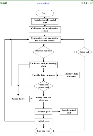
Figure 3: Flowchart Of System Operation With Wireless Network And Central Computer
4. EXPERIMENTS SETUP
Acceleration data were collected from the plate form, as shown in Figure 4, composed of; a three-
ISSN: 1992-8645 www.jatit.org E-ISSN: 1817-3195
system starts to collect the data of the vibration, the three axis sensor have been calibrated to adjust the new value based on the new position. Meanwhile, the wireless speed sensor established in front of the shift of the motor, the slot between the sensor and the shift does not exceed 0.5 cm. Eventually; the decision card was connected with a speed controller. Seems, the computer used with work is core i3, 4 GB RAM, which is connected with a system via two routers
Figure 4: Platform Of The Experiment Work When Collecting The Data For Learning
5. RESULT AND DISCUSSION
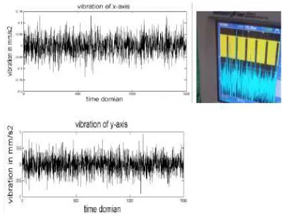
Actually, the acceleration data collected from the plate form will be transferred in a time domain with
a large amount of noise, as shown in Figure 5, where acceleration is expressed in mm/s2.
5.1 Time of wireless network processing
[image:6.612.90.297.209.364.2]Actually, the acceleration was obtained from the wireless sensors. However, the main challenge in the utilization of the wireless sensor is packet loss. Notably, packet loss in the industrial environment is preoperational with the distance of the nodes [20][27]. Seems, packet loss was neglected because the distances between the nodes were less than 5 m in this work, moreover, the prototype was developed which is failing when the packet losses, then, prototype gives this work high reliability in data collection. table 1 shows the time processing to this work which is related to 512*4 samples, the max time needed to collect and processing the data is 5.76 s.
Figure 5: Raw Vibration Acceleration Data Have Collected From Sample
Table 1: Scheme Of The Processing Time
Samples RPM, x,y,z
Time to collected via MATLAB (s)
Neural Online processing
(s)
Fuzzy processing
(s)
Computer bud rate
Samples/time (Sampling rate)
Sensor convenient
512 5.76 0.083 0.051 19200 88.8 0 ~40 Hz
5.892 s time processing with fault situation
5.2 Signal processing of the vibration data
The results of the signal processing steps are shown in detail in Figure 6 and 7. These steps involve reduction the noise and harmonic frequencies of the collected raw data, based on the utilized low-pass and band-pass filter. Thus, the acceleration data of 512 samples expressed in
mm/s2 were converted to velocity data expressed in
mm/s in one step of signal processing, depending on the category and integration of every four samples. The results shown in Figure 6 and 7
represent the vibration values after transfer in FFT form of resonant frequency to the (125/60) and (175/60) respectively, the FFT length is 128.
Clearly, vibration amplitudes in the 175 rpm situation are higher than that in the 125 rpm
situation because the vibration level is
preoperational with the frequency value, as shown in Equation 1.
sin
a
= −
A
ω
t
(1)(
)
speed rpm 60
[image:6.612.317.517.315.470.2]ISSN: 1992-8645 www.jatit.org E-ISSN: 1817-3195
where a denotes the acceleration of vibration in the
time domain, A denotes the acceleration amplitude,
2
f
ω
=
π
, and f denotes the frequency of the [image:7.612.113.292.189.348.2]machine (Hz) [31].
Figure 6: Vibration Data Have Filtering And Processing Of 125 Rpm, A- Vibration In X-Axis, B-
Vibration In Y-Axis, C- Vibration In Z-Axis
Figure 7: Vibration Data Have Filtering And Processing Of 175 Rpm In X,Y And Z Direction A- Vibration In X-Axis, B- Vibration In Y-Axis, C- Vibration
In Z-Axis
5.3 AI stage throughput
The neural technique is extensively utilized to identify and classify complex signals in the time and frequency domains [32][33]. In this study, the NN was utilized to distinguish between normal behavior and abnormal behavior based on
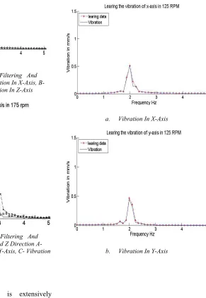
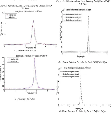
the vibration value, which is collected from the plate form. The NN backpropagation algorithm was utilized to train the data collected from the sample to represent the fault signal related to the behavior of vibrations. The six vibration signals shown in Figure 6 and 7 are the input and teaching data to the NN simultaneously. The continuous lines represent the teaching signals. Furthermore, the output of training NN in the off-line situation has been plotted as discrete lines with stars in Figure 8 and 9, where the system is at 125 and 175 RPM, respectively. Predominantly, the main aim of NNs was to obtain learning data with lower errors to compare the output and teaching signals.
a. Vibration In X-Axis
[image:7.612.226.517.261.681.2]ISSN: 1992-8645 www.jatit.org E-ISSN: 1817-3195
[image:8.612.92.523.71.260.2]c. Vibration In Z-Axis
Figure 8: Vibration Data Have Leering In Offline NN Of 125 Rpm.
A. Vibration In X-Axis
B. Vibration In Y-Axis
[image:8.612.98.526.263.699.2]C. Vibration In Z-Axis
Figure 9: Vibration Data Have Leering In Offline NN Of 175 Rpm
A-
Error Related To Velocity In X Y Z Of 175 Rpm
B- Error Related To Velocity In X Y Z Of 125 Rpm
ISSN: 1992-8645 www.jatit.org E-ISSN: 1817-3195
Indeed in this research, sugeno a fuzzy technique was implemented with NN to increase accuracy and classify the decision depending on
different situations. The fuzzy technique
implemented, with two input MFs and one output MF, was designed based on conditions of ISO 10816-3 and the motor speed. The design of the AI is based on the NN wake up the fuzzy if the vibration been abnormal values to classify the fault level. However, the fuzzy outcome-generating signal can feed to the control system for reducing
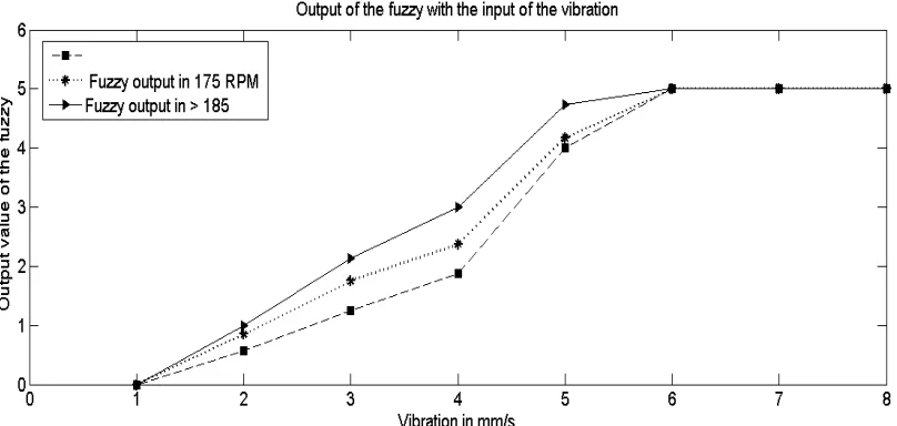
[image:9.612.103.507.263.455.2]the speed of the IM, when the vibrations were augmented during continuous operations, as illustrated in Figure 11, which is shows fuzzy throughput at different situations. Figure 11 displaying the fuzzy output increased with vibration. Eventually, the output will be generated as a voltage to control the speed of the motor to decrease the speed until the vibrations are in a safe zone or to shut down the system to prevent damage.
Figure 11: Illustrated Result Of The Fuzzy Technique In Online Training With Same Vibration Values But In Different Speeds As; 125,175,190 Rpm
5.4 Protection signal
The result of the last stage represented generating the action as a voltage for affected the chief signal of the speed controller based on the vibration fault values. Figure 12 displays the picture of the card has been constructed and the testing results to the same card. The oscilloscope picture is insight to; the main signal of the speed controller which dropping during the vibration fault rise, where it fusion via the fuzzy outcome, thus, the main signal return to normal case if the vibration dropping to zero. Actually, the last stage demonstrates of the successful for generate signal proportional with physical action to processing the system based reduce the speed for protecting the motor from the vibration rising.
Actually, the results can be discussing as; the data rate of the WVS illustrated the sensor proper for utilization with the rotor machine
ISSN: 1992-8645 www.jatit.org E-ISSN: 1817-3195
Figure 12: Illustrated Test Result And Picture Of The Decision Card
6. CONCLUSION
In this work, data modifying in the WVS to prepare the packet that it is transfer to the computer for signal processing and fault detection based on the FFT and AI respectively. Fuzzy output fusion to be proper for generating the signal can feed to speed control system via utilized the decision card. Result and analysis of this work showed that a new prototype was developed preventing the packet loss; because the system checked the packet parameter if lost one of them will declare which part is losing. Especially, if the machine getting problem related to misalignment the vibration value augmented with the speed, therefore, can decreasing the vibration via reducing the machine speed. Indeed, this work implemented based on that
behavior of the vibration was mentioned
previously. this research is useful because implemented integrated wireless fault diagnosis system can be utilized with anther rotor machine for protecting or prevention the damage may happen if the vibration rises, seems, system need modify conditions in WVS, decision card, and fuzzy data fusion based on the condition monitoring of the new machine. Future work, data can be classified and identified based on the vibration in the y-axis as an indicator of its amplitude.
ACKNOWLEDGMENTS
The author acknowledges the Razak School and the Malaysia–Japan International Institute of
Technology in University Technology Malaysia for supporting this work through a grant.
REFERENCE
[1] L. Hou and N. W. Bergmann, “Induction
Motor Fault Diagnosis Using Industrial Wireless Sensor Networks and Dempster-Shafer Classifier Fusion,” pp. 2992–2997, 2011.
[2] X. Zhang, Y. Liang, J. Zhou, and Y. Zang,
“A novel bearing fault diagnosis model integrated permutation entropy, ensemble
empirical mode decomposition and
optimized SVM,” Measurement, vol. 69, pp. 164–179, 2015.
[3] C. Park, R. Baek, W. Hoe, B. Kim, and H.
Lee, “Efficient Wireless Vibration Data Sensing and Signal Processing Technique Based on the Android Platform,” vol. 2014, 2014.
[4] G. Zhang, C. a. Duncan, J. Kanno, and R.
R. Selmic, “Unmanned Ground Vehicle
Navigation in Coordinate-Free and
Localization-Free Wireless Sensor and Actuator Networks,” J. Intell. Robot. Syst., vol. 74, no. 3–4, pp. 869–891, 2014.
[5] L. Hou and N. W. Bergmann, “Novel
industrial wireless sensor networks for machine condition monitoring and fault diagnosis,” IEEE Trans. Instrum. Meas., vol. 61, no. 10, pp. 2787–2798, 2012.
[6] X. Lei, P. Lu, and F. Liu, “The high
performance control for small rotary-wing unmanned aircraft based on composite control method,” Trans. Inst. Meas. Control, vol. 36, no. 8, pp. 1033–1040, 2014.
[7] M. KangaraniFarahani and S. Mehralian,
“Comparison between Artificial Neural Network and neuro-fuzzy for gold price prediction,” 2013 13th Iran. Conf. Fuzzy Syst., pp. 1–5, Aug. 2013.
[8] G. Marichal, M. Artes, and J. Garcia-Prada,
“An intelligent system for faulty-bearing detection based on vibration spectra,” J. Vib. Control, vol. 17, no. 6, pp. 931–942, Oct. 2010.
[9] T. Xie, H. Yu, and B. Wilamowski,
ISSN: 1992-8645 www.jatit.org E-ISSN: 1817-3195
[10] S. K. Jha, K. Hayashi, and R. D. S. Yadava,
“Neural, fuzzy and neuro-fuzzy approach for concentration estimation of volatile organic compounds by surface acoustic wave sensor array,” Measurement, vol. 55, pp. 186–195, 2014.
[11] A. S. Weddell, G. V. Merrett, S. Barrow,
and B. M. Al-Hashimi, “Vibration-powered sensing system for engine condition monitoring,” vol. 44, no. 0, pp. 1–5, 2012.
[12] R. K. Barai and K. Nonami, “Locomotion
Control of a Hydraulically Actuated Hexapod Robot by Robust Adaptive Fuzzy Control with Self-Tuned Adaptation Gain and Dead Zone Fuzzy Pre-compensation,” J. Intell. Robot. Syst., vol. 53, no. 1, pp. 35–56, 2008.
[13] S. Shamshirband, A. Amini, N. B. Anuar,
M. L. Mat Kiah, Y. W. Teh, and S. Furnell,
“D-FICCA: A density-based fuzzy
imperialist competitive clustering algorithm for intrusion detection in wireless sensor networks,” Meas. J. Int. Meas. Confed., vol. 55, pp. 212–226, 2014.
[14] E. T. Esfahani, S. Wang, and V.
Sundararajan, “Multisensor wireless system for eccentricity and bearing fault detection in induction motors,” IEEE/ASME Trans. Mechatronics, vol. 19, no. 3, pp. 818–826, 2014.
[15] C. Papachristos, K. Alexis, and A. Tzes,
“Dual–Authority Thrust–Vectoring of a Tri–TiltRotor employing Model Predictive Control,” J. Intell. Robot. Syst., 2015.
[16] I. Jawhar, N. Mohamed, J. Al-Jaroodi, and
S. Zhang, “A Framework for Using Unmanned Aerial Vehicles for Data Collection in Linear Wireless Sensor Networks,” J. Intell. Robot. Syst., vol. 74, no. 1–2, pp. 437–453, 2014.
[17] S. Mao, X. Shen, and M. Lu, “Virtual Laser
Target Board for Alignment Control and
Machine Guidance in Tunnel-Boring
Operations,” J. Intell. Robot. Syst., vol. 79, no. 3–4, pp. 385–400, 2015.
[18] V. C. Gungor, G. P. Hancke, and S.
Member, “Industrial Wireless Sensor
Networks : Challenges , Design Principles , and Technical Approaches,” vol. 56, no. 10, pp. 4258–4265, 2009.
[19] a D. Spacek, O. H. A. Junior, J. M. Neto, V.
L. Coelho, M. O. Oliveira, V. Gruber, and L. Schaeffer, “Management of Mechanical Vibration and Temperature in Small Wind Turbines Using Zigbee Wireless Network,” vol. 11, no. 1, pp. 512–517, 2013.
[20] A. Sabato and M. Feng, “Feasibility of
Frequency-Modulated Wireless
Transmission for a Multi-Purpose MEMS-Based Accelerometer,” Sensors, vol. 14, pp. 16563–16585, 2014.
[21] P. Li, L. Li, G. Song, and Y. Yu, “Wireless
Sensing and Vibration Control With Increased Redundancy and,” ieee, Trans. Cybern., vol. 44, no. 11, pp. 2076–2087, 2014.
[22] S. Yusuf, S. Shetty, N. Wilkinson, and D. J.
Brown, “A novel self-conFigure uring ethernet-based smart sensor application for
remote condition monitoring,” Mob.
Embed. …, 2013.
[23] P.-J. Chuang and Y.-J. Jiang, “Effective
neural network-based node localisation scheme for wireless sensor networks,” IET Wirel. Sens. Syst., vol. 4, no. 2014, pp. 97– 103, 2014.
[24] C. L. Tseng, S. Y. Wang, S. C. Lin, J. H.
Chou, and K. F. Chen, “A Motor Rotary Fault Diagnosis System Using Dynamic Structural Neural Network,” 2014 Int. Symp. Comput. Consum. Control, pp. 430– 433, 2014.
[25] P. Ballal, A. Ramani, M. Middleton, C.
McMurrough, A. Athamneh, W. Lee, C. Kwan, and F. Lewis, “Mechanical fault diagnosis using wireless sensor networks and a two-stage neural network classifier,” 2009 IEEE Aerosp. Conf., 2009.
[26] S. a. Yusuf, D. J. Brown, A. Mackinnon,
and R. Papanicolaou, “Application of dynamic neural networks with exogenous input to industrial conditional monitoring,” Proc. Int. Jt. Conf. Neural Networks, 2013.
[27] H. Lee, S. Member, Y. Chang, and Y.
Huang, “A Reliable Wireless Sensor System for Monitoring Mechanical Wear-Out of Parts,” vol. 63, no. 10, pp. 1–10, 2014.
[28] L. Hou and N. W. Bergmann, “Novel
ISSN: 1992-8645 www.jatit.org E-ISSN: 1817-3195
[29] J. Neuzil, O. Kreibich, and R. Smid, “A
Distributed Fault Detection System Based
on IWSN for Machine Condition
Monitoring,” vol. 10, no. 2, pp. 1118–1123, 2014.
[30] X. Fei, Z. Hao, and P. Daogang, “Fault
diagnosis in power plant based on multi-neural network,” Syst. Sci. Eng. ( …, 2014.
[31] Clarence W. & De Silva, Vibartion
Fundamentals and Practice, Second Edi. Taylor & France Group; Broken Sound Parkway NW., 2007.
[32] L. Facchini, M. Betti, and P. Biagini,
“Neural network based modal identification of structural systems through output-only measurement,” Comput. Struct., vol. 138, pp. 183–194, Jul. 2014.
[33] J. Ben Ali, N. Fnaiech, L. Saidi, B.
Chebel-Morello, and F. Fnaiech, “Application of
empirical mode decomposition and