IMPLEMENTATION OF DATA ENCODING AND DECODING
IN ARM BOARDS WITH QOS PARAMETERS
#1S.SUNDAR,*2R.KUMAR,#3HARISH M.KITTUR
#School of Electronics Engineering, VIT University Vellore – 632014, Tamilnadu, India. *Senior Consultant, WIPRO Technologies Chennai, Tamilnadu, India.
E-mail: [email protected],[email protected], [email protected]
ABSTRACT
Networks must be able to transfer data from one device to another with acceptable accuracy. For most of the applications, a system must guarantee that the data received are identical to the data transmitted. Any time data are transmitted from one node to the next, they can become corrupted in passage. Many factors can alter one or more bits of a message. Some applications require a mechanism for detecting and correcting errors and some applications may require retransmission of error data packets. In this paper, it is proposed to implement Hamming (7, 4) code for data encoding and decoding in LPC1788ARM Cortex boards .The proposal is aiming for detecting and correcting the error without any retransmission of error data. As RISC processor is used, the speed of execution is high and also QoS (Quality of Service) Parameters are used for measurement purpose which enable this proposal can be useful for high speed real time applications.
Keywords: Hamming Code (7, 4), LPC1788 ARM Board, UDP and QoS
1. INTRODUCTION
Data communications are the exchange of data between two devices via some form of transmission medium such as a wire cable. [1]The effectiveness of a data communications system depends on four fundamental characteristics: delivery, accuracy, timeliness, and jitter. The transmitting data may get corrupted in passage between one node to the next and resulting that can alter one or more bits of the the data.
Whenever bits flow from one point to another, they are subject to unpredictable changes because of interference. These unpredictable changes are also called as errors and in data communication and there are two types of errors available they are, single bit error and burst error. In the case of single bit error the interference causes a bit change from ‘0’ to ‘1’ or vice versa, whereas in burst error means that two or more bits in the data unit have changed. A burst error is most likely occur than single bit error and number of bits affected is depends on duration of noise and data rate. Date rate and error are directly related,if the data rate is high then error is also more.
To detect or correct the errors, extra bits (redundant bits) are added at the transmitter and
removed at the receiver.[2] If ‘n’ represents binary digits and ‘m’ represents bits associated with information then redundancy ‘r’ is defined as,
R = n/m ---(1)
Redundancy is the central concept of error detection and correction. As in error correction, we need to know number of bits corrupted and their location, it is clear that correction of error is more difficult than error detection. There are two principles are in practice for error correction and they are, forward error correction (FEC) and correction by retransmission. In FEC, the receiver uses redundant bits to estimate the presence of error whereas in correction by retransmission method, the receiver detects the error and asks the transmitter to retransmit the message again.
As the correction by error scheme is requiring a form of feedback between receiver and transmitter, fcc is preferred applications for which feedback is not feasible. [3,4] quality of service(QoS) is needed not only for ensuring better delivery of the information carried by the network but also for better utilization of the resources.
In this paper, two layer architecture is created in LPC1788 ARM cortex boards (with Linux OS installed) for message transmission and reception. If any error is present then it is identified and corrected without the need for retransmission.
2. DATA ENCODING AND DECODING
Hamming (7, 4) is a linear error-correcting code that encodes 4 bits of data into 7 bits by adding 3 parity bits. It is a member of a larger family of Hamming codes, Richard W. Hamming introduced in 1950. The Hamming code adds three additional check bits to every four data bits of the message. Hamming (7, 4) algorithm can correct any single-bit error, or detect all single-single-bit and two-single-bit errors. [5] it means, the minimal Hamming distance between any two correct code words is 3.the received words can be correctly decoded if they are at distance at most one from the codeword that was transmitted by the sender.
2.1 Encoding with Matrices
The trick to encoding with matrices is realizing that all the values that we need to deal with can be packed into right justified bytes (unsigned chars). Pack the data to be encoded into a byte and pack the columns of the generator matrix into another array of unsigned chars. The ith bit of a code word equals the data word times the ith column of the generator matrix, which is the ith entry in the array. Because of the way modulo 2 arithmetic works, this is just a bitwise AND operating of the two bytes followed by an XOR of each of the bits in the results.
According to the discussion in [6], a 4x7 generator matrix [G] can be used to transform four bits of data in to a seven bit Hamming code word. If we define‘d’ to be the 1×4 vector [d1 d2 d3 d4] then it is
possible to create a 4×7 generator matrix [G] such that the product modulo 2 of d and [G] (d [G]) is the desired 1×7 Hamming code word.
[6] In Hamming (7,4) code there are three parity bits P1,P2 and P3 which are defined as,
P1 = d2 + d3 + d4 --- (2)
p2 = d1 + d3 + d4--- (3)
p3 = d1 + d2 + d4 --- (4)
Now for encoding, the 4 bit data [1x4] bits are multiplied with 4x7 generator matrix.
2.2 Decoding:
A 3x7 parity check matrix [H] is used for validating the parity. [6]This matrix [H] may be constructed with three rows such that in each row 1 contains 1s in the position of the parity bit and all of the data bits that are included in its parity calculation. Then by multiplying the 3×7 matrix [H] by a 7×1 matrix representing the encoded data produces a 3×1 matrix. In this matrix if is all the elements are zeros, then the encoded data is error free. If the matrix has a non-zero value, then flipping the encoded bit that is in the position of the column in [H] that matches the matrix will result in a valid code word.
3. METHODOLOGY
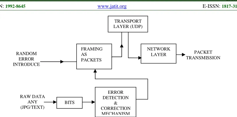
The Hamming (7,4) encoding and decoding logics are implemented in LPC178x/177x ARM boards. [7] The LPC178x/177x is an ARM Cortex-M3 based microcontroller for embedded applications requiring a high level of integration and low power dissipation. The bare ARM boards are loaded with Linux operating systems and then two layer architecture (DLL and UDP) is built on the boards based on Fig1 and Fig2 and these are respectively for encoding and decoding parts of the implementation.
3.1 Transmitter
PACKET RECEPTION
TRANSPORT LAYER (UDP)
NETWORK LAYER
DEFRAMING
ERROR DEDUCTION
ERROR CORRECTION
RAW DATA 3.2 Receiver
The receiver part of the implementation is based on Fig2.In this, deframing action is done over the received packets by the built Data Link Layer. Then Hamming decoding is done for extracting the data from the matrix. Error detection is done over the received data and if any error present then it will be removed and the corrected data is taken for the further use.
RANDOM ERROR INTRODUCE
RAW DATA ANY (JPG/TEXT)
BITS
ERROR DETECTION
& CORRECTION MECHANISM
PACKET TRANSMISSION TRANSPORT
LAYER (UDP)
FRAMING AS PACKETS
[image:3.612.106.513.71.272.2]NETWORK LAYER
Figure 1: Transmitter Part Of The Two Layer Architecture
4. IMPLEMENTATION CODE FLOW
There are four file names are used in the main functions and their roles are given below,
• Filename_1 is input file of the user, needs to change this filename same as user input file name.
• Filename_2 is temporary file name of the Hamming code, which receive the Encoded data
• Filename_3 receives any send data.
• After decoding, receive the decoded (Original) data to the Filename_4.
The nature of Hamming code input is 4 bit binary values and that will give the output as a 7bit binary value. In our Hamming code program we can give input as (alphabets, special characters, numbers, images, text doc, etc).
4.1 Transmitter part
The number of bytes send through UDP and from UDP is defined as,
#define udp buf_size 1024
Hamming transmit(char filename1[ ],char filename2[ ])
The function will read the data from user file each byte by byte and it send to Hamming code function to get the Hamming code and the Hamming code is written to temporary file (filename2). Each and every byte form input we have to convert as a nibble (4bits) then encode the each nibble.
• Hamming code(char data, unsigned char * buffer)
The function will convert each nibble as encoded byte that means one byte data will get two bytes of encoded data. That each two byte of encoded data going to be store in user filename2.
Get string from nibble(a, buff)
The above function get input as a nibble of data and it will return as a char buff.
• Hamming udp transmit(char filename2[])
The function takes the input from filename2. It reads the encoded data, and transmits through UDP to destination.
4.2 Receiver Part
HammingUDPReceive(charfilename3[ ], Unsigned long int file size)
The above function receives data through UDP and it will store the data in filename3. The data is received till the entire file size (count==file size).
HammingReceive(char filename3 [ ],char filename4[ ])
The above function will read byte by byte data from the filename3 and then send it to Hamming_decode function.
• Hamming decode(unsigned char edata[ ],char filename4[ ])
The above function will process the Hamming code data and generate actual data with error correction by calling the Decode function and saves the data in filename4.
• Decode (tmp,&correctdata)
The above function checks the data for errors and returns the corrected data if error is found or else will return the original data.
• Print Data From Hamming
5. EXPERIMENTAL SETUP AND RESULTS
[image:5.612.338.517.199.362.2]The simulation part of encoding and decoding are first implemented and checked in computer with Linux Platform. The simulation results are shown in Fig 3 and Fig 4 respectively.
[image:5.612.91.302.204.378.2]Figure 3:.Simulation result of Encoder
Figure 4: Simulation result of Decoder
Then the encoder and decoder parts are implemented in two Linux OS loaded ARM boards. The boards are connected through an Ethernet cable. The connection diagram is shown in Figure 5.
Figure 5: Experimental Setup
For communication, the boards are configured in hyper terminal as,
Board 1:
~ # ifconfig eth0 192.168.0.1 ~ # ./hamming 192.168.0.2 Board 2:
~ # ifconfig eth0 192.168.0.2 ~ # ./hamming 192.168.0.1
After completion of above steps the decoded image must be copied from root to sd-card or pen-drive. In this paper pen drive is used and to run with pen drive the following steps are executed.
~# cd decoded.jpg /usb/ ~# unmount /dev/sda1
[image:5.612.92.299.413.565.2]7. CONCLUSION
[8] ARM processors are embedded in products ranging from cell/mobile phones to automotive breaking systems in this paper, Hamming coding and decoding is implemented between two arm based boards with throughput and speed as QoS parameters for data transfer. As error detection and correction is implemented without any retransfer of data, this proposal is suitable for applications where retransmission is not possible or retransmission lead to increase overhead. Another feature of this implementation can be seen as; we can use this type of OS (Linux GPOS) for consumer electronics where the timing constraints are not critical. The future scope of this proposal is viewed like extending to wireless communication and as QoS parameters are used for measurement, the proposal can be useful for studying performances of Mobile Ad hoc (MANET) applications.
REFRENCES:
[1] Behrouz A.Forouzan,S Sophia Chung Fegan, “Data Communications and Networking”,
Fourth edition, McGraw-Hill Higher education.
[2] R.W. Hamming, “Error detecting and error correcting codes”, Bell Syst. Tech. J. 29 (1950) [3] Lei Chen and Wendi B. Heinzelman, “A Survey
of Routing Protocols that Support QoS in Mobile Ad Hoc Networks”, IEEE Network
November/December 2007.
[4] S. Sundar , R. Kumar , Harish M. Kittur ,and M.Shanmugasundaram, “MANET Routing Protocols With QoS Support- A
Survey”-International Journal of Engineering and Technology,ISSN0975-4024,Vol5No3,June/July
2013 ,pp.2077-2082.
[5] http://en.wikipedia.org/wiki/Hamming [6] http://michael.dipperstein.com/hamming [7] http://www.EmbeddedArtists.com
[8] Andrew.N.Sloss,Domnic Symes and Chris Wright, “ARM Systems Developers Guide
Designing and Optimizing System
[image:6.612.101.496.92.358.2]Software”,MORGAN KAUFMANN Publishers.