© 2016, IRJET ISO 9001:2008 Certified Journal
Page 1
DESIGN AND SIMULATION OF MINIATURIZED UWB MICROSTRIP PATCH
ANTENNA FOR WIRELESS COMMUNICATION
M.Gunavathi
1, P.Ramya
2, P.Hamsagayathri
3,D.Kavitha
41, 3,4P.G
Scholar,Department of Electronics and Communication, Bannari Amman Institute of
college,Sathyamangalam,Erode,Tamilnadu
2
AssistantProfessor, Department of Electronics and Communication, Bannari Amman Institute of college,
Sathyamangalam, Erode, Tamilnadu.
---***---Abstract -
This paper presents to design and analysis of double E-shaped microstrip patch antenna with UWB operating frequency range for wireless applications. In order to make the proposed double E-shape microstrip patch antenna by introducing the slots on both sides of the patch. This shape will provide UWB applications like WI-FI, WLAN, WIMAX, and satellite applications. The proposed antenna shape was simulated by using ADS software and it can analysed by using various terms and parameter of the antenna like bandwidth, return loss, gain, and radiation pattern. The proposed antenna can resonates at different level of frequency in the range of 3.0GHz, 4.44GHz, 5.07GHz, 6.22GHz, 6.92GHZ, 7.5GHz, 8.9GHz and 9.69GHz. These resonance frequencies are able to operate in the range of UWB applications. This antenna had the gain of 2.06dbi, 2.92, 3.42dbi, 4.96dbi, 5.23dbi, 5.28dbi, 6.03dbi, and 7.0dbi.Key Words:
Double E-shape micro strip patch, UWB, Multi
Band, Self Similarity, Directivity, Antenna Dimensions
1. INTRODUCTION
The microstrip patch antenna is a good choice for wireless mobile communication because it have several good characteristics like light profile, low wait, low fabrication cost and easy to fabricate. Antenna is a main building in wireless communication, Based on this antenna performance easily to analyse effectiveness of the wireless communication around the world. Antenna is a conductor which carrying the current.it is used to convert the electrical energy to electromagnetic waves and it can transmit over the longer distance. The main impact of the antenna in wireless communication is used to transmit and receive the information via the air.
The transmitting antenna have different ranges like Low frequency range, Mid frequency range, High frequency range, Ultra high frequency, and microwave frequency range.
In the transmitter side a radio transmitter supplies the electric current as electromagnetic waves. In the receiver side the antenna intercepts some of the power of an electromagnetic wave in order to produce a tiny voltage at its terminals, which is amplified by applying to receiver. antenna are essential components for all equipment that is used for radio broadcasting, television, two-way radio, communication receivers, radar, cell phones, and satellite communications as well as wireless microphones, Bluetooth enabled devices, wireless computer networks, and RFID. The antenna design can have different parameters like gain, VSWR, Directivity, Radiated power, efficiency, Return Loss, Impedance. The proposed E-shape microstrip patch antenna are simulated using HFSS software .Which operates in the range between 8.80GHz-13.49GHz.This structure is more suitable for wideband applications[1]the propose double E-shape fractal antenna was simulated by using ie3d software the operating frequency ranges of the designed antenna working in between 5.1 GHz- 9.6GHz with optimum gain and bandwidth .This design is adaptable for C,X and WLAN applications[2].To introduce the fractal structure in normal rectangular patch. It is more suitable for multiband applications. And compare performance of the antenna by using microstrip line feed and coaxial feed line. This antenna can resonate at three bands and which is more suitable for wideband applications. Compare to first iteration the antenna performance can improve in the second iteration method [3].The proposed E-shape fractal antenna is suitable for wide and ultra-frequency bands by using iteration and co-axial feed method.
© 2016, IRJET ISO 9001:2008 Certified Journal
Page 2
geometry applied patch antenna. The proposed fractalgeometry with patch is more suitable for GPS, UMTS, WIMAX applications with suitable bandwidth [5]. The proposed Minkowski curved antenna with second iteration is used to cover the GSM900/1710, GPS1227/1575, LTE and WIMAX 2500 and IEEE 802.11b applications The propose E-shape fractal with patch antenna is adapt for LTE,S-band applications, by introducing the fractal geometry the proposed design can achieve the various mobile standards applications[6].
2. DESIGN METHODOLOGY OF THE PROPOSED
ANTENNA
The main demand of antenna design for wireless communication is small size, low cost, easy to fabricate. The proposed antenna is widely satisfies the requirements of the wireless services. This structure can analyse using ADS software. The antenna performance can analysed the different parameters with corresponding resonance frequency.
2.1 Rectangular Microstrip Patch Antenna
To design the proposed E-shape antenna can make by using the rectangular patch. Initially the rectangular patch antenna was created and to introduce the slots with corresponding length and width to make the double E-shape antenna. It is designed by using FR4 substrate material with 1.6 mm with 4.4 dielectric constant value. The length and width of the antenna can calculate using the mathematical equations.
Step 1: Calculation of Width (W) of the Antenna
For an efficient radiator, practical width that leads to good radiation efficiencies is calculated by Transmission line model equation.
f0=c/2√ {εeff [(m/L) 2 + (n/W) 2]} (1)
Step2: Calculation of effective dielectric co-efficient (εreff)
The effective dielectric constant is obtained by referring to equation (2)
εreff= (εr+1)/2 + (εr-1)/2 [1+12W/h] 1/2(2)
Step 3: Calculation of effective length (Lreff)
The effective length can obtain by using mathematical equation (3)
LEFF=L +2∆L (3)
Step 4: Calculation of Length Extension (∆L)
The length extension can calculate by using equation (4)
∆L=0.412h (εreff+0.3) [W/h +0.264] / (εreff- 0.258) [W/h +0.8] (4)
Step 5: Calculation of Actual length (L)
The actual length can obtain by using the equation (5)
L =Leff-2L (5)
Step 6: Calculation of Ground Dimensions (Lg, Wg)
The transmission line model apply infinite ground plane only. However the practicalconsideration, it is essential to finite ground plane, it has been shows that finite and infinite ground plane can obtained. For this design the ground plane dimensions are given as:
L g=6h +L (3.6) (6)
Wg =6h +W (7)
2.2Geometry Of The E-Shape Patch Design
The double E-shape patch design can make by introducing slot on the rectangular patch antenna with correspondence length and width. The proposed antenna geometry can see belowthe figure 1.based on this designing parameter the antenna can satisfies the applications.
© 2016, IRJET ISO 9001:2008 Certified Journal
Page 3
2.3 Antenna SpecificationsTable-1: Parameters of the proposed antenna
2.4 System Architecture
The system architecture of proposed double E-Shape patch antenna are shown in figure 2.
Figure-2: System Architecture of Double E-shape patch design
Which indicates the proposed antenna applications based on the antenna parameter measurements like Return Loss (db), Gain(dbi), Bandwidth(GHz),Efficiency(%).
2.5 Feeding Techniques
The antenna performance is mainly depends on the feeding methods and its position. Based on this feeding
position we can easily to achieve the required applications. Antenna can feed by using various methods. These methods can be classified into two types-conducting and non-conducting. In this conducting method the RF power is inset directly to the radiating patch via connecting elements like microstrip line. In non-conducting method the electromagnetic field coupling is done to transfer the power between the microstrip line and the radiating patch.
The popular feeding methods are microstrip linefeed, coaxial probe(both conducting and non-conducting), aperture coupling, inset feed, and proximity feeding(both conducting and non-conducting).In this paper to simulate and analyse the proposed antenna parameter by using microstrip line feed method.
The main purpose of the Microstrip line feed cut in the patch is to match the impedance between the feed line and patch without the need for any additional matching element. This is accomplished by properly controlling the inset position. The main advantage this feed method is to ease to fabrication, simple to modelling and good impedance matching. The bandwidth range of this feeding technique in between 2-5%
3. SIMULATION SETUP
The simulation setup includes the designing requirements and steps of the proposed antenna implementations. Initially the rectangular patch antenna was designed with respect length and width.
Figure-3: Flow diagram of proposed antenna design
Parameter Dimensions(mm)
Rectangular patch
Length(L1) 10
Width(w1) 15
Double E-shape patch
length (L2) 12.8
Width(W2) 20
Feed line length(Lf) 2
width(Wf) 3.8
© 2016, IRJET ISO 9001:2008 Certified Journal
Page 4
Then this patch can simulate by using ADS software.toenhance the gain by introducing slot on both side of the patch. Again simulate and analyse the optimized parameter. After the simulation to adjust the length and width for adjusting the required frequency range. By using inset feed method easily to achieve the wide bandwidth. It is verified through ADS simulation via optimized parameters of the antenna. The flow diagram is shown in figure 3.
4. SIMULATED RESULTS AND DISCUSSION
To analyse and evaluate the antenna performance via the optimized parameters using ADS software. The simulated antenna results are return loss, ration pattern, current distribution, gain, directivity, and efficiency.
4.1RETURN LOSS
Return loss is the important parameter for to analyse the antenna performance in wireless environment. Because it is used to analyse effective power delivery of the designed antenna.
Figure-4: Return loss of the double E-shape patch antenna
From this result the peoples can easily understand the performance and the designed antenna is suitable for our required services. From this observation there are six resonance frequency are observed.at 4.434 GHz range the return loss value is -27.914dbi, At 5.787GHz the value of the return loss is -19.161dbi, At 7.072GHz the value of the return loss is -23.656dbi, At the resonance frequency range 7.648GHz the return loss value is -10.909dbi, At 9.0 GHz the return loss value is 19.26dbi, and the return loss value is -18.674 achieved at the resonance of 9.806GHz.From this loss the proposed antenna is suitable for UWB applications. Because the UWB frequency range occurs between 3.1GHz-10GHz.
4.2 ANTENNA PARAMETERS
The antenna parameters includes radiated power in watts, effective angle(steradian), Directivity(dbi),Gain(dbi), Maximum intensity(watts/steradian), angle of intensity maximum with respect to theta and phi values. The proposed antenna is resonates at different level of frequency with good return loss and power delivery ratio. Initially the radiated power in the range of 0.00041dbi, the gain value is 2.06dbi, the range of directivity isn8.64 dbi, maximum intensity is 0.00024(w/sr) at the resonance of 4.434 GHz with -27.9dbi return loss with 84.60% efficiency .The radiated power in the range of 0.00084dbi, the gain value is 3.42dbi, the range of directivity is 9.55 dbi, maximum intensity is 0.00060(w/sr) at the resonance of 5.787 GHzwith -19.16dbi return loss with 92.05% efficiency .The radiated power in the range of 0.00048dbi, the gain value is 4.96 dbi, the range of directivity is 11.182dbi,maximum intensity is 0.00050(w/sr) at the resonance of 7.072 GHz with -23.65dbi return loss with 88.54% efficiency .The radiated power in the range of 0.00048dbi, the gain value is 5.28 dbi, the range of directivity is 9.55 dbi, maximum intensity is 0.00060(w/sr) at the resonance of 7.648 GHz with -10.90dbi return loss with 94.27% efficiency .
The radiated power in the range of 0.00086dbi, the gain value is 5.23 dbi, the range of directivity is 9.76 dbi, maximum intensity is 0.00086(w/sr) at the resonance of 9.067 GHz with -19. 26dbi return loss with 85.81% efficiency . The radiated power in the range of 0.00077dbi, the gain value is 6.032 dbi, the range of directivity is 11.09 dbi, maximum intensity is 0.00077(w/sr) at the resonance of 9.80 GHz with -18.67 dbi return loss .
© 2016, IRJET ISO 9001:2008 Certified Journal
Page 5
Figure-5b: At 9.80GHzFigure-5:Antenna Parameter of the Double E-shape patch for resonance frequency 4.4 GHz and 9.80 GHz
4.3RADIATION PATTERN
[image:5.595.334.532.417.619.2]The radiation pattern defines the variation of the power radiated by an antenna as a function of the direction away from the antenna. The radiation pattern of the proposed antenna is shown in figure 6.
Figure -6a: At 4.4 GHz
The radiation pattern of the proposed antenna can analysed with corresponding resonance frequency of an antenna radiation pattern (or) antenna pattern defined as mathematical and graphical representation of radiation properties of the antenna.
Figure -6b: At 9.80GHz
Figure-6:Radiation Pattern of the Double E-shape patch for resonance frequency 4.4 GHzand 9.80 GHz.
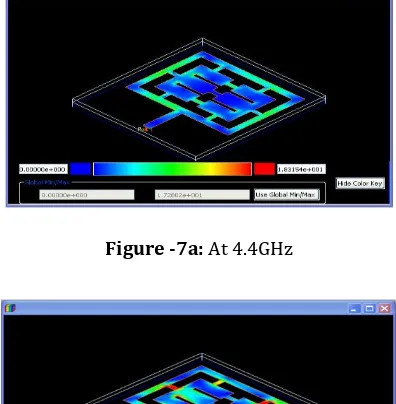
4.4 CURRENT DIATRIBUTION
The current distribution is the important parameter for analyse antenna performance. The red colour shows the maximum radiation of the antenna. The current distribution of the start (4.4GHz) and (9.80GHz) ending frequency range issee in figure 7.
Figure -7a: At 4.4GHz
Figure- 7b: At 9.80GHz
[image:5.595.59.268.478.618.2]© 2016, IRJET ISO 9001:2008 Certified Journal
Page 6
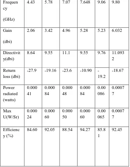
4.5RADIATION CHARACTERISTICS OF THE DOUBLEE-SHAPE ANTENNA
Frequen cy
(GHz)
4.43 5.78 7.07 7.648 9.06 9.80
Gain
(dbi)
2.06 3.42 4.96 5.28 5.23 6.032
Directivit y(dbi)
8.64 9.55 11.1 9.55 9.76 11.093
2
Return loss (dbi)
-27.9 -19.16 -23.6 -10.90
-19.2 -18.67 Power radiated (watts) 0.000 41 0.000 84 0.000 48 0.000 84 0.00 086 0.0007 7 Max U(W/Sr) 0.000 24 0.000 60 0.000 50 0.000 60 0.00 065 0.0007 7 Efficienc y (%)
84.60 92.05 88.54 94.27 85.8
1
[image:6.595.30.288.146.476.2]92.45
Table -2:Radiation characteristics of the double E-shape patch antenna
5. CONCLUSION
The proposed double E-shape patch antenna is design and simulated using ADS Software. From the analysis of the proposed antenna result this structure is very suitable for ultra-wide band applications. The resonance frequency of this structure is 4.4GHz, 5.787 GHz, 7.072 GHz, 7.648 length and width of the patch to achieve high gain, directivity with sufficient efficiency.
FUTURE WORK
To Introduce the fractal on the E-shape patch for enhancement the gain and bandwidth, and compare the fractal with double E-shape patch antenna parameters with different feed line results using ADS software.
REFERENCES
[1] InduBalaPauria, Sachin Kumar, Sandhya Sharma, “Design and Simulation of E-shape microstrip Patch Antenna for Wideband Applications,”International Journal of Soft Computing and Engineering (IJSCE),ISSN: 2231-2307, Volume-2, Issue-3, July 2012.
[2] VijetaAttri, Vishal Dora, and Rajesh Goel. “Double E-Shaped Multiband Fractal Microstrip Patch Antenna for wireless Applications,” International Journal of Application or Innovation in Engineering Management( IJAIEM),Volume 3, Issue 6, June 2014.
[3] Arun, Ankita Mittal, “Multiband Fractal Microstrip Patch for Wireless Applications,” International Journal of Advanced Research in Electronics and Communication Engineering (IJARECE),Volume 3, Issue 9, September 2014 963 ISSN:2278-909X.
[4] Sukhveer Singh, SavinaBansal, and Suhjinder Singh, “Design and Analysis of E-shape Sierpinski Fractal Antenna,” International Journal of Advanced Research in Electronics and Communication Engineering (IJARECE),
Volume 4,Issue 8, August 2015.
[5] A.Janani, A.Priya, “Design of E-Shape fractal Simple Multiband Patch Antenna for S-Band LTE and Various Mobile Standards,” International Journal of Engineering And Science, Volume 3, Issue 1(May 2013), pp 12-19, ISSN(e): 2278-4721, ISSN(p): 2319-6483.
[6] S.Shubhangi, B.GhorpadeVidya ,V.Babare, and U,Deshmukh, “Comparison of E-Shape Microstrip Antenna And E-Shape Fractal Antenna,” International Journal of Engineering Research and Technology(IJERT), Volume 2, Issue 4, April-2013,ISSN: 2278-0181.
[7] NimaBayatmaku, ParisalLotfi, Mohammadnaghi Azarmanesh, and Sabersoltani, “Design of Simple Multiband Patch Antenna for Mobile Communication Applications Using New E-Shape Fractal,” IEEE Antennas and Wireless Propogation Letters ,Vol.10, 2011.
[8] A.Nagpal, S.Singh, and A.Mrwaha, “ Multiband E-Shaped Fractal Microstrip Patch Antenna with DGS for Wireless Applications,”IEEE International Conference on
Computational Intelligence and Communication Networks , Mathura, India, PP22-26.
[9] Khidre ,Lee, Elsherbeni, and Fan Yang, 2013, “Wide Band Dual Beam U-Slot MicrostripAntenna,”IEEE Transactions And Propagation ,Vol 61, No.3, Pp 1415-1418.
[10] Gupta, Singh, and MArwaha, “Dual Band U-Slotted Microstrip Patch Antenna for C band and X band Radar,” Proceeding of 5thIEEE International Conference on Computational Intelligence and Communication Networks,