A DSRC Transceiver with Multi Mode
Encoder using SOLS Technique
Vysakh
#1, Rahul M Nair
#2,
#1PG Student, Department of ECE, NCERC Pampady.india #2Asst.professor , Department of ECE, , NCERC Pampady india Abstract: An intelligent transportation system (ITS)
is a technology, a platform or application that efficiently improves the quality of vehicle transportation. To promote the intelligent transportation system into our daily life, we can make use of the dedicated short range Communication (DSRC) technique in to the field of automobile industries. The FM0 and Manchester codes are used to reach the dc-balance in dedicated short range communication systems. The diversity between the FMO and Manchester codes seriously limits the area utilization and power consumption. In proposed system SOLS technique is used to overcome this limitation. In this Project, an efficient DSRC encoder and decoder is proposed with ASK modulator with minimum area utilization with the help of similarity oriented logic simplification technique.
Keywords - Dedicated short-range communication (DSRC), FM0, Manchester, VLSI.
I. INTRODUCTION
The dedicated short-range communication (DSRC) is a protocol specially designed for the intelligent transportation system, in which the communication between each and every vehicles may be one way or two way communication. The DSRC consist of both vehicle to Vehicle (v2v) communication as well as vehicle to roadside infrastructure (v2r) communication. The vehicle to vehicle communication mainly deals with the forward collision warning, emergency electronic break light, blind spot or lane change warning, do not pass warning etc. At the same time the vehicle to infrastructure communication includes the Electronic Toll Collection (ETC), curve speed warning, red light violation warning, spot weather information warning, reduced speed zone warning, stop sigh gap assistance etc.
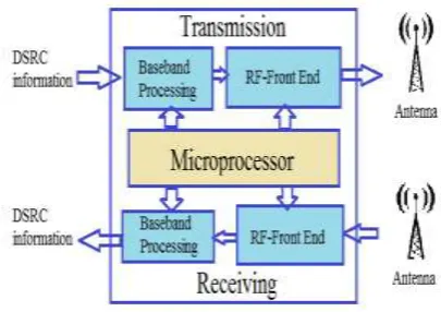
The DSRC transmission system architecture consists of three modules. For the transmission and reception of data, the RF front end can be used. The overall system process controlling and task scheduling is done with the help of a microprocessor. The main part of the DSRC transceiver is the baseband processing. The major function of the base band processing includes modulation, error
correction, clock synchronization, and encoding or decoding. When the channel is in idle condition, there may be the chance of occurrence of noise. This chance will reduce with the help of FM0 or Manchester encoding technique.
Fig. 1 System architecture of DSRC transceiver
The hardware usage become more and this will affects the performance of the proposed system if we implement the design for FM0 and Manchester encoder separately. So to improve the hardware utilization ratio of the system, a new architecture is proposed through this project called the Similarity Oriented Logic Simplification (SOLS). This technique also improves the performance and area utilization.
Several organizations in different countries have been developed this system. The DSRC standards of America, Europe, and Japan are shown in Table I.
TABLEI
PROFILE OF DSRC STANDARDS FOR AMERICA, EUROPE, AND JAPAN
Europe America Japan
Organisation CEN1 ASTM2 ARIB3
Data Rate 500 kbps
27 Mbps 4 Mbps
Carrier Frequency
5.8 GHz 5.9 GHz 5.8 GHz
Modulation ASK, PSK
OFDM ASK
Encoding (Downlink)
FM0 Manchester Manchester
It is difficult to obtain dc-balance for the transmitted binary signals. The purposes of FM0 and Manchester codes are to provide the transmitted signal with dc-balance.
II. RELATEDWORKS
In this section, the previous works related to the DSRC transceiver is mentioned.
Yu-Cherng Hung et al. [6] proposed a High-Speed CMOS Chip Design for Manchester and Miller Encoder. The main concept behind this work is parallel operation to improve data throughput and also the technique of hardware sharing is adopted in this design to reduce the number of transistors.
P, Benabe et al.[4] presented a Manchester code generator running at 1 ghz. This design uses 32 transistors and the design complexity is same as that of the D flip flop. The major advantage of this design is the clock frequency is same as the frequency of data. It is intended to be used in a complex opticalcommunication system.
Daniel jiang et al. [3] proposed the design of 5.9 GHz dedicated short range communication based vehicular safety communication. In the DSRC based intelligent transportation system, each and every vehicles continuously send the data to another vehicle or road side infrastructure. Therefore, channel congestion control is particular concern and also need to improve the broadcast system. Therefore a concurrent multichannel operational scheme is needed.
III.FM0ANDMANCHESTERENCODING TECHNIQUE
Both the Manchester and FM0 encoding techniques are used in this multimode encoder. The input data and the clock signal and are abbreviated in the following section as X and CLK respectively.
A. Manchester Encoding
The output expression of a Manchester encoder can derive as follows
X ⊕ CLK (1)
The figure 2 shows the design of a simple Manchester encoder using XOR gate with X and CLK as the input and CODE as the output.
(a)
(b)
Fig.2 Manchester encoding (a) Example of Manchester coding (b) Realisation of Manchester coding
B. FM0 Encoding
Title For the illustration of FM0 coding, we can consider a single clock signal. Split the clock signal as former half cycle CLK,A and later half cycle CLK,B. FM0 coding is based on the following set of rules.
1) The fm0 signal shows a transition between the former and later half cycle A and B if X is at logic-0 .
2) The fm0 signal do not show any transition between the former and later half cycle A and B if X is at logic-1 .
3) A transition must be allocated between each clock cycles without considering the value of X.
So according to the above set of rules, we can design the fm0 encoder as shown below.
Fig.3 Example of FM0 coding
Fig.4 State definition of FM0 code
Figure 4 shows four states s1=11, s2=10, s3=01, s4=00. These four states follow the 3 rules as mentioned above.
From the state definition we get the current and previous states clearly and we can easily create the FSM as shown in figure 5.
Fig.5 FSM representation of FM0 coding.
TABLEIII
TRANSITION TABLE OF FM0
Previous State Current State
A(t-1) B(t-1) A(t) B(t)
X=0 X=1 X=0 X=1
1 1 0 0 1 0
1 0 1 1 0 1
0 1 0 0 1 0
0 0 1 1 0 1
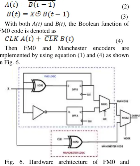
From the transition table, we get the Boolean functions for both the current states A(t) and B(t) as
(2)
(3) With both A(t) and B(t), the Boolean function of FM0 code is denoted as
(4) Then FM0 and Manchester encoders are implemented by using equation (1) and (4) as shown in Fig. 6.
Fig. 6. Hardware architecture of FM0 and Manchester encodings.
According to equation (1), Manchester encoder can be implemented simply by using only one X-OR gate. In the fm0 logic, two D flip flops namely DFF A and DFF B are needed for storing the FM0 state code. MUX−1 will either pass A(t) or B(t) here the control signal is CLK. By using equation (2) and (3), A(t) and B(t) can be implemented easily. There is an input signal called Mode, used for determining the mode of the multimode encoder. The encoder act as FM0 encoder for Mode = 0 and Manchester encoder for Mode = 1. We can calculate the hardware utilization rate ( HUR ) as
HUR
(5)
The active component means the components that are active for the working of either FM0 or Manchester encoder. The total components are the total number of components involved in both the encoding schemes.
TABLEIIIII
HUR OF FM0 AND MANCHESTER ENCODING
coding Active components/ Total componenets
HUR
FM0 6/7 85.71%
Manchester 2/7 28.57%
IV. SIMILARITY ORIENTED LOGIC SIMPLIFICATION TECHNIQUE IN FM0 AND MANCHESTER ENCODER
The main purpose of similarity oriented logic simplification (SOLS) technique is to design a fully reused VLSI architecture for FM0 and Manchester encodings. This technique can be divided in to two parts. First one is area compact retiming and another one is balance logic operation sharing.
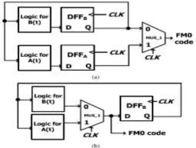
1) Area Compact Retiming: The logic design shown in figure 7(a) is the simplified form of the fm0 part we already discussed in figure 6 in which x is eliminated for the concise representation of the diagram. According to equation (2) and 3, it is clear that the FM0 encoder only require DFF B to store the previous state B(t-1). So we can directly remove the DFF A from the design, but it cause some non synchronization in our design between A(t) and B(t) causes the logic fault of FM0 code.
Fig. 7. Illustration of area-compact retiming on FM0 encoding architecture. (a) FM0 encoding without area-compact retiming. (b) FM0 encoding with area-compact retiming.
This logic fault can be eliminated by shifting the DFFB just after the mux1 where the DFFB is assumed to be positive-edge triggered. Now either A(t) or B(t) is alternatively pass throw the mux-1 with the control signal CLK. The timing diagram remains same even if we relocate DFF B or not as shown in figure 8.
Fig. 8. Timing diagram of area-compact retiming for FM0 encoding.
TABLEIVV
TRANSISTOR COUNT OF FM0 ENCODING ARCHITECTURE WITH AREA COMPACT RETIMING
Without area compact retiming
With area compact retiming
PMOS 36 25
NMOS 36 25
Total 72 50
If the above design is implemented with logic-family of static CMOS, the total transistor count is shown in Table IV. The total transistor count without area compact retiming is 72 but if we apply the area compact retiming, the total transistor count reduced to 50.
2) Balance Logic-Operation Sharing: The Manchester encoder need only one xor gate for implementation.
(6)
But the same function can be implemented using a multiplexer so that we can easily integrate and X with A(t) and B(t) according to equation (4) and (6).
Fig. 9 Concept of balance logic-operation sharing
for FM0 and Manchester encodings. (a) Manchester encoding in multiplexer. (b) Combines the logic operations of Manchester and FM0 encodings.
Fig. 10. Balance logic-operation sharing of A(t)
and .
and the same multiplexer. So logic operation sharing become balanced here.
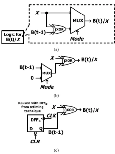
Fig. 11. Balance logic-operation sharing of B(t)
and X. (a) Without the XOR sharing. (b) With XOR sharing. (c) Sharing of the reused DFFB from area-compact retiming technique.
The same idea can be also adopted to the logic for
B(t)/X, as shown in Fig. 11(a). the logic is directly implemented according to equation (3) for B(t) and x can be directly pass through the mux. But the main disadvantage of this logic is that, the xor gate is only the part of FM0 encoding but is not shared with Manchester coding technique. Therefore the hardware utilization ratio is again become limited in this case. So to improve the HUR, we can interpret x as x xor 0. Now the xor gate shifter right to the multiplexer as shown in Fig. 11(b), where the multiplexer is responsible to switch the operands of
B(t−1) and logic-0. In this architecture, both x and B(t) shares a common xor gate so HUR increases. Again improve the hardware utilization ratio by replacing the multiplexer with DFF B. so the number of components again reduces and the remaining components will share both fm0 and Manchester encoding. In DFF B one inpit signal is B(t-1) and instead of the input zero, CLR signal is used. Now the HUR become 100 % .
The proposed VLSI architecture of FM0/Manchesterencoding using SOLS technique is shown in Fig. 12(a). If mode is 0 and CLR is 1, the encoder act as FM0 encoder and if mode is 1 and CLR is 0, the encoder act as Manchester encoder.
The computation time for both xor gate and mux2 are same. However, the logic for A(t)/ further incorporates an inverter in the series of MUX−2. This make an unbalance computation time between
logic for A(t)/ and B(t)/X results in the glitch to MUX−1, possibly causing the logic-fault on coding. To eliminate this unbalance computation time, the architecture of the balance computation time between A(t)/ and B(t)/X is just changed as shown in Fig. 12(b).
Fig. 12. VLSI architecture of FM0 and Manchester encodings using SOLS technique.(a) Unbalance computation time between A(t)/ and
B(t)/X. (b) Balance computation time between A(t)/X
and B(t)/X.
The XOR in the logic for B(t)/X is changed into the XNOR, and the inverter in the logic is shifted just after the mux1. Now, the logic computation time between both the logic for A(t)/ and B(t)/X is become balanced. The multimode encoder will work according to the mode and CLR signals.
V. ASK MODULATOR
VI. ERROR DETECTION AND CORRECTION
In between source and destination there may be a chance of noise in the communication channel. This noise can make changes in the original information. In this project, hamming code is used for error detection and correction purpose. To find out the errors and correction we need some extra bits called redundancy bits. Equation for generating redundancy bit is
2^ r >= D + r + 1 (7) Here r = number of redundancy bit
D = number of information data bit
There for to send a 25 bit information we need minimum 5 redundancy bits.
Calculating the redundancy bit by using the following formulas.
r (1) = 1,2,4,5,7,9,11,12,14,16,18,20,22,24. r(2) = 1,3,4,6,7,10,11,13,14,17,18,21,22,25 r(4) = 2,3,4,8,9,10,11,15,16,17,18,23,24,25 r(8) = 5,6,7,8,9,10,11,19,20,21,22,23,24,25 r(16)= 12,13,14,15,16,17,18,19,20,21,22,23,24,25 Then place the redundancy bit in appropriate position and send it to the receiver. At the receiving end, the error can be detected using the following formula.
Err_add(1) = 1,3,5,7,11,13,15,17,19,21,23,27,29 Err_add(2)=2,3,6,7,10,11,14,15,18,19,22,23,26, 27,30
Err_add(3)=4,5,6,7,12,13,14,15,20,21,22,23,28, 29,30
Err_add(4)=8,9,10,11,12,13,14,15,24,25,26,27,28 ,29,30
Err_add(5)=16,17,18,19,20,21,22,23,24,25,26,27, 28,29,30
Now we get an error value which gives the exact position of the error. Now we can just toggle the value for correcting the error.
VII. RESULTS AND DISCUSSION
A DSRC transceiver with multimode encoder using SOLS technique is written in verilog language and compiled and simulated using modelsim. The circuit simulated and synthesized. An error correction technique is also included in this project with the help of hamming code and implemented the design in FPGA hardware.
VIII. CONCLUSIONS
Combining both fm0 and Manchester encoding schemes enable the usage of the DSRC system in different countries. But the diversity between the Manchester and fm0 coding will limit the hardware
utilization ratio. In this paper, the fully reused VLSI architecture using SOLS technique for both FM0 and Manchester encodings is proposed. The similarity oriented logic simplification technique eliminates the limitation on hardware utilization by two main ideas: area compact retiming and balance logic operation sharing. After applying the SOLS technique, the design can achieve 100% HUR.
REFERENCES (SIZE 10 & BOLD)
[1] F. Ahmed-Zaid, F. Bai, S. Bai, C. Basnayake, B. Bellur, S. Brovold, et al. , ―Vehicle safety communicate ons—Applications (VSC-A) final report,‖ U.S. Dept. Trans., Nat. Highway Traffic Safety Admin., Wash- ington, DC, USA, Rep. DOT HS 810 591, Sep. 2011.
[2] J. B. Kenney, ―Dedicated short-range communications (DSRC) standards in the United States,‖ Proc. IEEE , vol. 99, no. 7, pp. 1162–1182, Jul. 2011.
[3] J. Daniel, V. Taliwal, A. Meier, W. Holfelder, and R. Herrtwich, ―Design of 5.9 GHz DSRC-based vehicular safety communication,‖ IEEE Wireless Commun. Mag. , vol. 13, no. 5, pp. 36–43, Oct. 2006.
[4] P. Benabes, A. Gauthier, and J. Oksman, ―A Manchester code generator running at 1 GHz,‖ in Proc. IEEE, Int. Conf. Electron., Circuits Syst., vol. 3. Dec. 2003, pp. 1156–1159.
[5] A. Karagounis, A. Polyzos, B. Kotsos, and N. Assimakis, ―A 90nm Manchester code generator with CMOS switches running at 2.4 GHz and 5 GHz,‖ in Proc. 16th Int. Conf. Syst., Signals Image Process., Jun. 2009, pp. 1–4.
[6] Y.-C. Hung, M.-M. Kuo, C.-K. Tung, and S.-H. Shieh, ―High-speed CMOS chip design for Manchester and Miller encoder,‖ in Proc. Intell. Inf. Hiding Multimedia Signal Process. , Sep. 2009, pp. 538–541.
[7] M. A. Khan, M. Sharma, and P. R. Brahmanandha, ―FSM based FM0 and Miller encoder for UHF RFID tag emulator,‖ in Proc. IEEE Adv. Comput. Conf. , Mar. 2009, pp. 1317–1322. [8] J.-H. Deng, F.-C. Hsiao, and Y.-H. Lin, ―Top down design of joint MODEM and CODEC detection schemes for DSRC coded-FSK systems over high mobility fading channels,‖ in Proc. Adv. Commun. Technol. Jan. 2013, pp. 98–103.
[9] Yu - H s u a n L e e, Cheng-Wei Pan, ―Fully Reused VLSI Architecture of FM0/Manchester Encoding Using SOLS Technique for DSRC Applications ,‖ in ieee transactions on very large scale integration (vlsi) systems. , January 2015.
[10] H. Zhou and A. Aziz, ―Buffer minimization in pass transistor logic,‖ IEEE Trans. Comput. Aided Des. Integr. Circuits Syst. , vol. 20, no. 5, pp. 693–697, May 2001.
[11] Yu-Hsuan Lee, and Cheng-Wei Pan, ‖Fully Reused VLSI Architecture of FM0/Manchester Encoding Using SOLS Technique for DSRC Applications‖ IEEE transactions on very large scale integration (VLSI) systems, vol. 23, no. 1, january 2015.
[12] Zakkam Manoj Kartiek, S. Rajendra Kumar, ―VLSI Modelling of High Speed Area Efficient Encoding Technique in Dedicated Short Range Communication Application Systems,‖ in International Journal of Emerging Engineering Research and Technology Volume 3, Issue 6, June 2015, PP 128-132