Review
A Comprehensive Study of Key Electric Vehicle (EV)
Components, Technologies, Challenges, Impacts, and
Future Direction of Development
Fuad Un-Noor 1, Sanjeevikumar Padmanaban 2,*, Lucian Mihet-Popa 3, Mohammad Nurunnabi Mollah 1 and Eklas Hossain 4
1 Khulna University of Engineering and Technology, Department of Electrical and Electronic Engineering, Khulna 9203, Bangladesh; [email protected] (F.U); [email protected] (M.N.M)
2 Department of Electrical and Electronics Engineering, University of Johannesburg, Auckland Park, South Africa ; [email protected]
3 Faculty of Engineering, Østfold University College, Kobberslagerstredet 5, 1671 Kråkeroy; Building: S 316, Norway ; [email protected]
4 Oregon Tech, Department of Electrical Engineering & Renewable Energy, OR-97601, USA; [email protected]
* Correspondence: [email protected]; Tel.: +27-79-219-9845
Abstract: Electric vehicles (EV) are getting more commonplace in the transportation sector in recent times. As the present trend suggests, this mode of transport is likely to replace the internal combustion engine (ICE) vehicles in near future. Each of the main EV components has a number of technologies that are currently in use or can become prominent in the future. EVs can cause significant impacts on the environment, power system, and other related sectors. The present power system can face huge instabilities with enough EV penetration; but with proper management and coordination, EVs can be turned into a major contributor to the successful implementation of smart grid. There are possibilities of immense environmental benefits as well, as the EVs can extensively reduce the greenhouse gas emission from the transportation sector. However, there are some major obstacles for EVs to overcome before replacing the ICE vehicles totally. This paper is focused on reviewing all the useful data available on EV configurations, energy sources, motors, charging techniques, optimization techniques, impacts, trends, and possible directions of future developments. Its objective is to provide an overall picture of the current EV technology and ways of future development to assist in future researches in this sector.
Keywords: Electric Vehicle; internal combustion engine; greenhouse gas; optimization techniques; Battery Electric Vehicle (BEV); Hybrid Electric Vehicle (HEV); Plug-in Hybrid Electric Vehicle (PHEV); Fuel Cell Electric Vehicle (FCEV).
1. Introduction
In recent times, electric vehicles (EV) are gaining popularity, and the reasons behind it are many. The most eminent one is its contribution in reducing greenhouse gas (GHG) emission. In 2009, the transportation sector emitted 25% of the GHG produced from energy related sectors [1]. EVs, with enough penetration in the transportation sector, are expected to reduce that. But this is not the only reason that is bringing this century old and once dead concept back to life, and in a commercially viable and available product as well. As a vehicle, an EV is quiet, easy to operate, and does not require fuel costs associated with conventional vehicles. As an urban transport, it is highly useful. It does not use any stored energy or cause any emission while idling, capable of frequent start-stop, provides the total torque from the startup, and does not require any trip to the gas station. It does not cause any smog that is making the city air highly polluted either. The instant torque makes it highly preferable for motorsport. The quietness and low infrared signature makes it useful in military use as well. The power sector is going through a changing phase where renewable
sources are gaining momentum. The next generation power grid, called ‘smart grid’ is also being developed. EVs are being considered a major contributor to this new power system comprised of renewable generating facilities and advanced grid system. All these have led to a renewed interest and development in this mode of transport.
The idea to employ electric motors to drive a vehicle surfaced after the innovation of the motor itself. From 1897 to 1900, the EVs became 28% of the total vehicles and were preferred over the internal combustion engine (ICE) ones [1]. But the ICE types gained momentum afterwards, and with oil prices very low, they soon conquered the market, became much more mature and advanced, and EVs got lost into oblivion. A chance of resurrection appeared in the form of the EV1 from general motors, which was launched in 1996, and quickly became very popular. Other leading carmakers, including Ford, Toyota, and Honda brought out their own EVs as well. Toyota’s highly successful Prius, the first commercial hybrid electric vehicle (HEV), was launched in Japan in 1997, with 18,000 units sold in the first year of production [1]. Today, almost none of those twentieth century EVs exist; an exception can be Toyota Prius, still going strong in a better and evolved form. Now the market is dominated by Nissan Leaf, Chevrolet Volt, and Tesla Model S; whereas the Chinese market is in the grip of BYD Auto Co., Ltd.
EVs can be considered as a combination of different subsystems. Each of these systems interact with each other to make the EV work, and there are multiple technologies that can be employed to operate the subsystems. In fig. 1, key parts of these subsystems and their contribution to the total system is demonstrated. Some of these parts have to work extensively with some of the others, whereas some have to interact very less. Whatever the case may be, it is the combined work of all these systems that make an EV operate.
Figure 1: Major EV subsystems and their interactions [2].
conversion systems are demonstrated in sections VI and VII. Section VIII discusses the effects EVs create in different sectors. Being a developing technology, EVs still have many limitations that have to be overcome to enable them to penetrate deeper into the market. These limitations are pointed out in section IX along with probable solutions. Section X summed up some strategies used in EVs to enable proper use of the available power, followed by section XII containing the trends and sectors that may get developed in the future. The topics covered in this paper have been discussed different literatures. Over the years, a number of publications have been made discussing different aspects of EV technology. This paper is created as an effort to sum up all these works to demonstrate the state-of-the art of the system and to position different technologies side by side to find out their merits and demerits, and in some cases, which one of them can make its way to the future EVs.
2. EV types
EVs can run solely on electric propulsion or they can have an ICE working alongside it. Having only batteries as energy source makes the basic kind of EVs, but there are kinds that can employ other modes of energy source. These can be called as hybrid EVs (HEV). The International Electrotechnical Commission’s Technical Committee 69 (Electric Road Vehicles) proposed that vehicles using two or more types of energy source, storage or converters can be called as an HEV as long as at least one of those provide electrical energy [2]. This definition makes a lot of combination possible for HEVs like ICE and battery, battery and flywheel, battery and capacitor, battery and fuel cell etc. Therefore, common population and specialists both started calling vehicles with an ICE and electric motor combination HEVs, battery and capacitor ones ultra-capacitor assisted EV and the ones with battery and fuel cell as FCEVs [2]. These terminologies has become widely accepted and according to this norm, EVs can be categorized as following:
1. Battery Electric Vehicle (BEV) 2. Hybrid Electric Vehicle (HEV)
3. Plug-in Hybrid Electric Vehicle (PHEV) 4. Fuel Cell Electric Vehicle (FCEV)
2.1. Battery Electric Vehicle (BEV)
EVs with only batteries to provide power to the drivetrain are known as BEVs. BEVs have to rely solely on the energy stored in their battery packs, therefore the range of such vehicles depends directly on the battery capacity. Typically they can cover 100-250 km on one charge [3], whereas the top-tier models can go a lot further, from 300 to 500 km [3]. These ranges depend on driving condition and style, vehicle configurations, road conditions, climate, battery type and age. Once depleted, charging the battery pack takes quite a lot of time compared to refueling a conventional ICE vehicle. It can take as long as 36 hours completely replenish the batteries [4][ 5], there are far less time consuming ones as well, but none is comparable to the little time required to refill a fuel tank. Charging time depends on the charger configuration, its infrastructure and operating power level. Advantages of BEVs are their simple construction, operation and convenience. These do not produce any greenhouse gas (GHG), do not create any noise and therefore beneficial to the environment. Electric propulsion provides instant and high torques, even at low speeds. These advantages, coupled with their limitation of range, makes them the perfect vehicle to use in urban areas. Nissan Leaf and Teslas are some high-selling BEVs these days, along with some Chinese vehicles.
Figure 3: Federal Urban Driving Schedule torque-speed requirements [2].
2.2. Hybrid Electric Vehicle (HEV)
HEVs employ both an ICE and an electrical powertrain to power the vehicle. The combination of these two can come in different forms which are discussed later. An HEV uses the electric propulsion system when the power demand is low. It is a great advantage in low speed conditions like urban areas, it also reduces the fuel consumption as the engine stays totally off during idling periods, for example, traffic jams. This feature also reduces the GHG emission. When higher speed is needed, the HEV switches to the ICE. The two drivetrains can also work together to improve the performance. Hybrid power systems are used extensively to reduce or to completely remove turbo lag in turbocharged cars, like the Acura NSX. It enhances performance also by filling the gaps between gear shifts and providing speed boosts when required. The ICE can charge up the batteries, HEVs can also retrieve energy by means of regenerative braking.
Therefore, HEVs are primarily ICE driven cars that use an electrical drivetrain to improve mileage or for performance enhancement. To attain these features. HEV configurations are being widely adopted by car manufacturers.
Figure 4: HEV basic operating principle [6].
Figure 5: Power control strategy of HEV [6].
2.3. Plug-in Hybrid Electric Vehicle (PHEV)
PHEVs start in ‘all electric’ mode, runs on electricity and when the batteries are low in charge, it calls in the ICE to provide a boost or to charge up the battery pack. The ICE is used here to extend the range. PHEVs can charge their batteries directly from the grid (which HEVs cannot), they also have the facility to utilize regenerative braking. PHEVs’ ability to run solely on electricity for most of the time makes its carbon footprint smaller than the HEVs. They consume less fuel as well and thus reduces the associated cost. The vehicle market is now quite populated with these, Chevrolet Volt and Toyota Prius sales show their popularity as well.
2.4. Fuel cell electric vehicle (FCEV)
FCEVs also go by the name FCV (Fuel Cell Vehicle). They got the name as the heart of such vehicles are fuel cells that use chemical reaction to produce electricity [13]. Hydrogen is the fuel of choice for FCVs to carry on this reaction, so they are often called ‘hydrogen fuel cell vehicles’. FCVs carry the hydrogen in special high pressure tanks, another ingredient for the power generating process is oxygen, which it acquires from the air sucked in from the environment. Electricity generated from the fuel cells goes to an electric motor which drives the wheels. Excess energy is stored in storages like batteries or supercapacitors [14-16]. Commercially available FCVs like Toyota Mirai or Honda Clarity use batteries for this purpose. FCVs only produce water as a byproduct of its power generating process which is ejected out of the car through the tailpipes. An advantage of such vehicles is they can produce their own electricity which emits no carbon, enabling it to reduce its carbon footprint further than any other EV. Another major advantage of these are, and maybe the most important one right now, refilling these vehicles takes the same amount of time required to fill a conventional vehicle at a gas pump. It makes adoption of these vehicles more likely in the near future [2], [17]. Major obstacle in adopting this technology is the scarcity of hydrogen fuel stations, but then again, BEV or PHEV charging stations were not a common scenario even a few years back. A report to the U.S. Department of Energy (DOE) pointed to another disadvantage which is the high cost of fuel cells, that they charge more than $200 per kW, which is far greater than ICE (less than $50 per kW) [18], [19]. There are also concerns regarding safety in case of flammable hydrogen leaking out of the tanks. With these obstacles gone, FCVs can really be the future of cars. The possibilities of using this technology in supercars is shown by Pininfarina’s H2 Speed. [20] compared BEVs and FCEVs in different aspects, where FCEVs appeared to outshine BEVs in all future scenarios.
Figure 6: FCEV configuration.
Fig 8: Advanced battery EV attribute and fuel cell EV attribute ratio for 320- and 480-km (200- and 300-mile) range, with assumptions of average US grid mix in 2010–2020 time-range and all hydrogen made from natural
gas (values greater than one indicate a fuel cell EV advantage over the battery EV) [20].
[21] predicted a bit different future for FCVs. It showed a plug-in fuel cell vehicle (PFCV) with a larger battery and smaller fuel cell, which makes it battery dominant car. According to [21], if hydrogen for such vehicles can be made from renewable sources to run the fuel cells and the energy to charge the batteries come from green sources as well, these PFCVs will be the future of vehicles. The FCVs we see today, will not have much appeal other than some niche markets.
Figure 9: PFCV shown in [21].
Table 1: Comparison of different vehicle types [2].
EV type
Driving component
Energy
source Features Problems
BEV Electric motor Battery Ultracapacitor
No emission Not dependent on oil Range depends largely on the
type of battery used Available commercially
Battery price and capacity
Range Charging time Availability of charging stations
High price
HEV Electric motor ICE
Battery Ultracapacitor
ICE
Very little emission Long range
Can get power from both electric supply and fuel
Complex structure having both
Management of the energy sources Battery and engine
electrical and mechanical drivetrains Available commercially
FCEV Electric motor Fuel cell
Very little or no emission High efficiency Not dependent on supply of
electricity High price Available commercially
Cost of fuel cell Feasible way to produce fuel Availability of fueling facilities
3. EV configurations
An electric vehicle, unlike its ICE (Internal Combustion Engine) counterparts, is quite flexible [2]. It is because of the absence of intricate mechanical arrangements that are required to run a conventional vehicle. In an EV, there is only one moving part, the motor. It can be controlled by different control arrangements and techniques. The motor needs a power supply to run which can be from an array of sources. These two components can be placed at different locations on the vehicle and as long as they are connected through electrical wires, the vehicle will work. Then again, an EV can run solely on electricity, but an ICE and electric motor can also work in conjunction to turn the wheels. Because of such flexibility, different configurations emerged which are adopted according to the type of vehicle.
An EV can be considered as a system incorporating three different subsystems [2]: energy source, propulsion and auxiliary. The energy source subsystem includes the source, its refueling system and energy management system. The propulsion subsystem has the electric motor, power converter, controller, transmission and the driving wheels as its components. The auxiliary subsystem is comprised of auxiliary power supply, temperature control system and the power steering unit.
Figure 10: EV subsystems [2].
The arrows indicate the flow of the entities in question. A backward flow of power can be created by regenerative actions like regenerative braking. The energy source has to be receptive to store the energy sent back by regenerative actions. Most of the EV batteries along with capacitors/flywheels (CFs) are compatible with such energy regeneration techniques [2].
3.1. General EV setup
that allows the wheels to rotate at different speeds. Fig. 11(b) shows a configuration with the clutch omitted. It has a fixed gear in place of the gearbox which removes the chance of getting the desired torque-speed characteristics. The configuration of fig. 11(c) has the motor, gear and differential as a single unit that drives both the wheels. Nissan Leaf, as well as the Chevrolet Spark, uses an electric motor mounted at the front to drive the front axle. In fig. 11(d), a configuration to obtain differential action by using two motors for the two wheels. Mechanical interaction can be further reduced by placing the motors inside the wheels to produce an ‘in-wheel drive’. A planetary gear system is employed here because advantages like high speed reduction ratio and inline arrangement of input and output shafts. Mechanical gear system is totally removed in the last configuration [fig. 11(e)] by mounting a low-speed motor with an outer rotor configuration on the wheel rim. Controlling the motor speed thus controls the wheel speed and the vehicle speed.
Figure 11: Different front wheel drive EV configurations [2].
EVs can be built with rear wheel drive configuration as well. The single motor version of Tesla Model S uses this configuration. Nissan BladeGlider is a rear wheel drive EV with in-wheel motor arrangement. The use of in-wheel motors enables it to apply different amount of torques at each of the two rear wheels to allow better cornering.
Figure 12: Tesla Model S, rear wheel drive configuration [22].
Figure 13: Tesla Model S, all-wheel drive configuration [22].
AWD configurations are useful to provide better traction in slippery conditions, they can also use torque vectoring for better cornering performance and handling.
AWD configuration can also be realized for in-wheel motor systems. It can prove quite useful for city cars like the Hiriko Fold which has steering actuator, suspension, brakes and a motor all integrated in each wheel. Such arrangements can provide efficient all wheel driving, all wheel steering along with ease of parking and cornering.
Figure 14: Hiriko Fold.
In-wheel motor configurations are quite convenient in the sense that it reduces the weight of the drivetrain by removing central motor, related transmission, differential, universal joints and drive shaft [23]. It also provides more control, better turning capabilities and more space for battery, fuel cell or cargo. But in this case the motor is connected to the power and control systems through wires that can get damaged because of harsh environment, vibration and acceleration, thus causing serious trouble. Sato et al. proposed a wireless in-wheel motor system (W-IWM) [24].
Simply put, the wires are replaced by two coils which are able to transfer power in-between them. Because of vibrations caused by road conditions, the motor and the vehicle can be misaligned and can cause variation in the secondary side voltage.
Figure 15: Conventional and wireless IWM [24].
coupling in a series-parallel arrangement can provide a transmitting efficiency of 90% in both directions at 2kW [27]. Therefore, W-IWM is compliant with regenerative braking as well.
Figure 16: W-IWM setup showing efficiency at 100% torque reference [24].
Figure 17: Experimental vehicle with W-IWM system by Sato et al. [24].
Different algorithms are used to create the traction control systems in different vehicles. It can also be employed using fuzzy logic applied to a neural network [23]. In [23], a fuzzy controller is used for controlling the yaw rate and another one is used to prevent saturation of tire forces. Another method of increasing stability by measuring the lateral forces experienced by the tires is shown in [28].
Figure 19: Different forces acting on a vehicle [23].
FCEVs have the same driving principle as the BEVs, they does not require an ICE, therefore these configurations apply for FCEVs as well.
3.2. HEV setup
HEVs use both an electrical propulsion system and an ICE. Various ways in which these two can be set up to spin the wheels creates different configurations that can be summed up in four categories [1]:
1. Series hybrid 2. Parallel hybrid 3. Series-parallel hybrid 4. Complex hybrid
3.2.1. Series hybrid
This configuration is the simplest one to make an HEV. Only the motor is connected to the wheels here, the engine is used to run a generator which provides the electrical power. It can be put as an EV that is assisted by an ICE generator [2].
Figure 20: Drivetrain of series hybrid system [29].
Table 2: Properties of series configuration [30].
Advantages
Efficient and optimized power-plant Possibilities for modular power-plant
Optimized drive line
Long lifetime Mature technology
Fast response
Capable of attaining zero emission
Limitations
Large traction drive system Requirement of proper algorithms
Multiple energy conversion steps
3.2.2. Parallel hybrid
This configuration connects both the ICE and the motor in parallel to the wheels. Either one of them or both take part in delivering the power [2]. It can be considered as an IC engine vehicle with electric assistance [2]. The energy storages in such a vehicle can be charged by the electric motor by means of regenerative braking or by the ICE when it produces more than the power required to drive the wheels.
Figure 21: Drivetrain of parallel hybrid system [29].
Table 3: Properties of parallel configuration [30].
Advantages
Capable of attaining zero emission Economic gain
More flexibility
Limitations
Expensive Complex control
Requirement of proper algorithms Need of high voltage to ensure efficiency
Table 4: Comparison of parallel and series configurations [30].
Parameters Parallel HEV Series HEV
Voltage 14V, 42V, 144V, 300V 216V, 274V, 300V, 350V, 550V, 900V
Power requirement 3-40 KW >50 KW
Relative gain in fuel economy
(%) 5-40 >75
In an effort to combine both the series and the parallel configuration, this system acquired an additional mechanical link compared to the series type, or an extra generator when compared to the parallel type. It provides the advantages of both the systems but more costly and complicated nonetheless. Complication in drivetrain is caused to some extent by a planetary gear unit [29]. A less complex alternative to this system is to use a transmotor, which is a floating-stator electric machine. In this system the engine is attached to the stator, and the rotor stays connected to the drivetrain wheel through the gears. The motor speed is the relative speed between the rotor and the stator and controlling it adjusts the engine speed for any particular vehicle speed [29].
Figure 22: Drivetrain of series-parallel hybrid system using planetary gear unit [29].
Figure 24: Drivetrain of series-parallel hybrid system using transmotor [29].
3.2.4. Complex hybrid
This system has one major difference with the series-parallel system, that is, it allows bidirectional flow of power whereas the series-parallel can provide only unidirectional power flow. But by current market terminologies, this configuration too is denoted as series-parallel system. High complexity and cost is a drawback of this system too but it is adopted by some vehicles to use dual-axle propulsion [2].
Constantly variable transmission (CVT) can be used for power splitting in a complex hybrid system or choosing between the power sources to drive the wheels. Electric arrangements can be used for such processes and is dubbed as e-CVT. It is developed and introduced by Toyota Motor Co. CVTs can be implemented hydraulically, mechanically, hydro-mechanically or electromechanically [32]. Two methods of power splitting - input splitting and complex splitting are shown in [32]. Input splitting got the name as it has a power split device placed at the transmission input. This system is used by certain Toyota and Ford models [32]. [32] also showed different modes of these two splitting mechanisms and provided descriptions of e-CVT systems adopted by different manufacturers.
Figure 26: Compound split e-CVT system [32].
Such power-split HEVs require two electric machines, wheels, an engine and a planetary gear (PG), combining all of them can be done in twenty-four different ways. If another PG is used, that number gets greater than one thousand. An optimal design incorporating a single PG is proposed in [33]. Four wheel drive (4WD) configurations can benefit from using a two-motor hybrid configuration as it nullifies the need of a power transmission system to the back wheels (as they get their own motor) and provides the advantage of energy reproduction by means of regenerative braking [34]. A stability enhancement scheme for such a configuration by controlling the rear motor is shown in [34].
4. Energy sources
EVs can get the energy required to run from different sources. The criteria such sources have to satisfy are mentioned in [2], high energy density and high power density being two most important ones [29]. There are other characteristics that are sought after to make a perfect energy source, fast charging, long service and cycle life, less cost and maintenance being a few of them. High specific energy is required from a source to provide a long driving range whereas high specific power helps to increase the acceleration. Because of the diverse characteristics that are required for the perfect source, quite a few sources or energy storage systems (ESS) come into discussion, they are also used in different combinations to provide desired power and energy requirements [2].
4.1. Battery
Batteries have been the major energy source for EVs for a long time, though of course, with the flow of time, different battery technologies have been invented and adopted and this process is still going on. Some of such variants are: lead-acid, Ni-Cd, Ni-Zn, Zn/air, Ni-MH, Na/S, Li-Polymer and Li-Ion batteries. [35] showed the advantages, structural model and application of a battery made out of graphene for EV use.
Different battery types have their own pros and cons, and while selecting one, these things have to be kept in mind. [36] provided key features of some known batteries which is demonstrated in table 6.
Table 5: Performance goal of EV batteries as set by USABC (U.S. Advanced Battery Consortium) [2].
Parameters Mid-term Long-term
Primary goals Energy density (C/3 discharge rate) (Wh/l) 135 300 Specific energy (C/3 discharge rate)
(Wh/kg)
80 (Desired: 100) 200
Power density (W/l) 250 600
Specific power (80% DOD/30s) (W/kg) 150 (Desired: 200)
400
Lifetime (year) 5 10
Cycle life (80% DOD) (cycles) 600 1000
Price (USD/kWh) <150 <100
Operating temperature (̊C) -30 to 65 -40 to 84
Recharging time (hour) <6 3 to 6
Fast recharging time (40% to 80% SOC) (hour)
0.25
Secondary goals
Self-discharge (%) <15 (48 hour) <15 (month) Efficiency (C/3 discharge, 6 hour charge)
(%)
75 80
Maintenance No maintenance No
maintenance
Resistance to abuse Tolerance Tolerance
Thermal loss 3.2 W/kWh 3.2 W/kWh
Table 6: Common battery types [36,37-45]
Battery type Components Advantage Disadvantage
Lead-acid • Negative active
material: spongy lead
• Positive active material: lead
• Available in
production volume • Comparatively low
in cost
• Mature technology
• Cannot discharge more than 20% of its capacity
oxide • Electrolyte:
diluted sulfuric acid
as used for over fifty years
a deep rate of SOC (state of charge)
• Low energy and
power density • Heavier
• May need
maintenance NiMH (Nickel–Metal Hydride) • Electrolyte: alkaline solution • Positive electrode: nickel hydroxide • Negative
electrode: alloy of nickel, titanium, vanadium and other metals.
• Double energy
density compared to lead-acid
• Harmless to the environment
• Recyclable
• Safe operation at high voltage
• Can store
volumetric power and energy
• Cycle life is longer • Operating
temperature range is long
• Resistant to
over-charge and discharge
• Reduced lifetime of around 200-300 cycles if discharged rapidly on high load currents
• Reduced usable
power because of memory effect Li-Ion (Lithium-Ion) • Positive electrode: oxidized cobalt material • Negative electrode: carbon material • Electrolyte: lithium salt solution in an organic solvent
• High energy
density, twice of NiMH
• Good performance
at high temperature
• Recyclable
• Low memory effect
• High specific
power
• High specific
energy
• Long battery life, around 1000 cycles
• High cost
• Recharging still takes quite a long time, though better than most batteries
Ni-Zn (Nickel-Zinc) • Positive electrode: nickel oxyhydroxide • Negative electrode: zinc
• High energy
density
• High power
density
• Uses low cost
material
• Capable of deep cycle
• Friendly to
environment • Usable in a wide
temperature range from -10°C to 50°C
• Fast growth of
dendrite,
Ni-Cd (Nickel-Cadmium) • Positive electrode: nickel hydroxide • Negative electrode: cadmium
• Long lifetime • Can discharge fully
without being damaged
• Recyclable
• Cadmium can
cause pollution in case of not being properly disposed of
• Costly for
vehicular application
Table 7: Comparison of different battery types [46]
Advantages over Lead-acid Ni-Cd (Nickel-Cadmiu m) NiMH (Nickel–Meta l Hydride) Li-Ion (Lithium-Ion) Convention al Polymer
Lead-acid • Volumetric
energy density • Gravimetric
energy density
• Range of
operating temperature
• Rate of
self-discharge • reliability • Volumetric energy density • Gravimetric energy density
• Rate of
self-dischar ge • Volumetri c energy density • Gravimet ric energy density
• Rate of
self-disch arge • Volumetri c energy density • Gravimetr ic energy density
• Rate of
self-disch arge • Design characteri stics Ni-Cd (Nickel-Cadmiu m) •Output voltage •Cost •Higher cyclability • Volumetric energy density • Gravimetric energy density • Volumetri c energy density • Gravimet ric energy density
• Rate of
self-disch arge • Output voltage • Volumetri c energy density • Gravimetr ic energy density
• Rate of
self-disch arge • Design characteri stics NiMH (Nickel–Metal Hydride) •Output voltage •Cost •Higher cyclability
• Range of
operating temperature •Cost • Higher
cyclability
• Rate of
self-discharge • Volumetri c energy density • Gravimet ric energy density • Range of
operating temperat ure • Volumetri c energy density • Gravimet ric energy density • Range of
operating temperatu re
• Rate of
• Design characteri stics Li-Ion (conventional) •Cost •Safety •Higher cyclability •Recyclabili ty
• Range of
operating temperature • Cost • Safety •Higher cyclability • Recyclability • Cost • Safety
• Rate of
discharge • Recyclabili ty • Volumetri c energy density • Gravimet ric energy density (potential ) • Cost • Design characteri stics • Safety Li-Ion (polymer) •Cost •Higher cyclability
• Range of
operating temperature • Higher cyclability • Cost • Volumetric energy density • Cost • Higher cyclability
• Range of operating temperat ure • Higher cyclability Absolute advantages •Cost •Higher cyclability • Cost
• Range of
operating temperature • Volumetric energy density • Volumetri c energy density • Gravimet ric energy density •Range of
operating temperatu re
•Rate of
self-disch arge • Output voltage • Volumetri c energy density • Gravimet ric energy density • Range of
operating temperatu re
• Rate of
self-disch arge • Output voltage • Design characteri stics
Figure. 28: Battery cell arrangement in a battery pack.
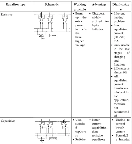
Table 8: Equalizer characteristics [47,48-53]
Equalizer type Schematic Working
principle
Advantage Disadvantag
e
Resistive • Burns
up the extra power in cells that have higher voltage
• Cheapest, widely
utilized for laptop
batteries
• Inherent heating problem • Low
equalizing current (300-500) mA
• Only usable in the last stages of charging and flotation • Efficiency is
almost 0% • All
equalizing current transforms into heat for EV
application, therefore not
recommend ed
Capacitive • Uses
switche d capacito rs • Switche
• Better current capabilities than resistive equalizers
• Unable to control inrush current • Potentiall
s capacito rs from cell to cell to transfer energy from higher energy cell to lower energy ones
• No control issue • Simple implementat ion current ripples can flow for big cell voltage difference s • Cannot provide any required voltage difference which is essential for SOC equalizati on Inductiv e
Basic • Energy
is transfer red from higher energy to lower energy cells by using inductor s • Relatively simple
• Capable of transporting high amount of energy • Can handle
complex control schemes like voltage difference control and current limitation • Can compensate for internal resistance of cells • Increased equalizing current • Not dependent on cell voltage • Requires additional component s to prevent ripple currents • Needs two
switches in addition to drivers and controls in each cell • Current distributio n is highly concentrate d in neighborin g cells because of switching loss
Cuk • Has all the
advantages of inductive equalizres • Can complex
power capacitors • Subjected to loss caused by series capacitor • A little less
efficient than typical inductive equalizers • Faces problems during distributin g equalizing currents all over the cell string • May need
additional processing power Tran sfo rm er based • Theoretically permits proper current distribution in all cells without addition control or loss • Complex transforme r with multiple secondary, which is very much challenging to mass produce
• Not an
current imbalance
Table 9: Equalizers compared; a + sign indicate an advantage whereas the – signs indicate drawbacks [47].
Lithium-Ion batteries are being used everywhere these days. It has replaced its lead-acid counterpart and became a mature technology itself. Its popularity can be justified by the fact that best-selling EVs, for example, Nissan Leaf and Tesla Model S – all use this battery [54, 55]. Better battery technologies are discovered already, but they are not being pursued because of the exorbitant cost associated with their research and development, lithium batteries also have lots of scopes to improve [56]. So it can be said that, lithium batteries will dominate the EV scene for quite some time to come.
Table 10: Battery parameters of some current EVs [3].
Model Total energy (kWh) Usable energy
(kWh) Usable energy (%)
i3 22 18.8 85
C30 24 22.7 95
B-Class 36 28 78
e6 61.4 57 93
RAV4 41.8 35 84
4.2. Ultracapacitor (UC)
Figure. 29
:
An UC cell [59].EVs go through start/stop conditions quite a lot, especially in urban driving situations. This make the battery discharge rate highly changeable. The average power required from batteries is low, but during acceleration or conditions like hill-climb a high power is required in a short duration of time [2], [36]. The peak power required in a high-performance electric vehicle can be up to sixteen times the average power [2]. UCs fit in perfectly in such a scenario as it can provide high power for short durations. It is also fast in capturing the energy generated by regenerative braking [2], [36]. A combined battery-UC system negates each other’s shortcomings and provides an efficient and reliable energy system. The low cost, load levelling capability, temperature adaptability and long service life of UCs make them a likable option as well [2,29].
Figure. 30: Combination of battery and UC [60].
4.3. Fuel cell (FC)
Fuel cells generate electricity by electrochemical reaction. An FC has an anode (A), a cathode (C) and an electrolyte (E) between them. Fuel is introduced to the anode, gets oxidized there, the ions created travels through the electrolyte to the cathode and combines with the other reactant introduced there. The electrons produced by oxidation at the anode produce the electricity. Hydrogen is used in FCEVs because of its high energy content, being non-polluting (producing only water as exhaust) and being abundant in nature in form of different compounds such as hydrocarbons [2]. Hydrogen can be stored in different methods for use in EVs [2], commercially available FCVs like Toyota Mirai use cylinders to store it.
Figure. 31: Working principle of FC [2].
Figure. 32: Hydrogen fuel cell configuration [36].
Table 11: Different FC constructions and their characteristics [2].
PAFC AFC MCFC SOFC SPFC DMFC
Working temp. (̊C) 150-210 60-100 600-700 900-1000 50-100 50-100 Power density (W/cm2) 0.2-0.25 0.2-0.3 0.1-0.2 0.24-0.3 0.35-0.6 0.04-0.25
Estimated life (kh) 40 10 40 40 40 10
Estimated cost (USD/kW) 1000 200 1000 1500 200 200
PAFC: Phosphoric acid fuel cell AFC: Alkaline fuel cell SOFC: Solid oxide fuel cell
SPFC: Solid polymer fuel cell, also known as proton exchange membrane fuel cell
losses. Response time of FCs is comparatively higher to UCs or batteries [36]. Because of these reasons, another storage is used alongside FC, like battery or UC. Toyota Mirai uses batteries to power its motor, the FC is used to charge the batteries. The batteries receive the power reproduced by regenerative braking as well. This combination provides more flexibility as the batteries do not need to be charged, only the fuel for the FC has to be replenished and it takes far less time than recharging the batteries.
4.4. Flywheel:
Flywheel is used as an energy storage by using the energy to spin the flywheel which keeps on spinning because of inertia. The flywheel acts as a motor during the storage stage. When the energy is needed to be recovered, the flywheel’s kinetic energy can be used to rotate a generator to produce power. Advanced flywheels can have their rotors made out of sophisticated materials like carbon composites and are placed in a vacuum chamber suspended by magnetic bearings.
Figure. 33: Flywheel used in F1 KERS system.
Table 12: Material used for flywheels [63].
Material Density
(kg/m3)
Tensile
strength (mpa) Max energy
density (mj/kg)
Cost (USD/kg)
Monolithic
material 4340 steel 7700 1520 0.19 1
Composites
E-glass 2000 100 0.05 11
S2-glass 1920 1470 0.76 24.6
Carbon
T1000 1520 1950 1.28 101.8
Carbon
AS4C 1510 1650 1.1 31.3
Flywheels offer a lot of advantages over other storages for EV use as they are lighter, faster and more efficient to absorb power from regenerative braking, faster to supply a huge amount of power in a short time when rapid acceleration is needed and can go through a lot of charge-discharge cycles over its lifetime. They are especially favored for hybrid racecars which go through a lot of abrupt braking and acceleration, which are also at much higher g-force than normal commuter cars. Storage systems like batteries or UCs cannot capture the energy generated by regenerative braking in situations like this properly. Flywheels, on the other hand, because of their fast response, have a better efficiency in similar scenarios, by making use of regenerative braking more effectively, it reduces pressure on the brake pads as well. Porsche 911GT3R hybrid made use of this technology.
Table 13: Relative energy and power densities of different energy storage systems [64].
Storage system Vehicles using the system
Battery Tesla Model S, Nissan Leaf
Fuel cell + battery Toyota Mirai, Honda Clarity
Flywheel Porsche 911GT3R Hybrid
5. Motors used
The propulsion system is the heart of an EV [65-70], and the electric motor sits right in the core of the system. The motor converts electrical energy that it gets from the battery into mechanical energy which enable the vehicle to move. It also acts as a generator during regenerative action which sends energy back to the energy source. Based on their requirement, EVs can have different numbers of motors. Toyota Prius has one, Acura NSX has three – the choice depends on the type of the vehicle and the functions it is supposed to provide. [2] and [21] listed the requirements for a motor for EV use which includes high power, high torque, wide speed range, high efficiency, reliability, robustness, reasonable cost, low noise and small size. DC motor drives demonstrate some required properties needed for EV application, but their lack in efficiency, bulky structure, lack in reliability because of the commutator or brushes present in them and associated maintenance requirement made them less attractive [2], [29]. With the advance of power electronics and control systems, different motor types emerged to meet the needs of the automotive sector, induction and permanent magnet (PM) types being the most favored ones [29,21,71].
5.1. Brushed DC Motor
These motors have permanent magnets (PM) to make the stator, rotors have brushes to provide supply to the stator. Advantages of these motors can be the ability to provide maximum torque in low speed. The disadvantages, on the other hand, are its bulky structure, low efficiency, heat generated because of the brushes and associated drop in efficiency. The heat is also difficult to remove as it is generated in the center of the rotor. Because of these reasons, brushed DC motors are not used in EVs any more [71].
5.2. Permanent Magnet Brushless DC Motor (BLDC)
The rotor of this motor is made of PM (most commonly NdFeB [2]), the stator is provided an AC supply from a DC source through an inverter. As there are no windings in the rotor, rotor copper loss is absent which makes it more efficient than induction motors. This motor is also lighter, smaller, better at dissipating heat (as it is generated in the stator), more reliable, has more torque density and specific power [2].But because of its restrained field-weakening ability, the constant power range is quite short. The torque also decreases with increased speed because of back EMF generated in the stator windings. The use of PM increases the cost as well [29,71]. However, enhancement of speed range and better overall efficiency is possible with additional field windings [2,72]. Such arrangements are often dubbed as PM hybrid motors because of the presence of both PM and field windings. But such arrangements too are restrained by complexity of structure, the speed ratio is not enough to meet the needs of EV use, off roaders specifically [29]. PM hybrid motor can also be constructed using a combination of reluctance motor and PM motor. Controlling the conduction angle of the power converter can improve the efficiency of PM BLDCs as well as speed range, reaching as high as four times the base speed, though the efficiency may decrease at very high speed resulting from demagnetization of PM [2].
Figure. 35: Characteristics of Permanent Magnet Brushless DC Motor.
5.3. Permanent Magnet Synchronous Motor (PMSM)
These machines are one of the most advanced ones, capable of being operated at a range of speeds without the need of any gear system. This feature makes these motors more efficient and compact. This configuration is also very suitable for in-wheel applications, as it is capable of providing high torque, even at very low speeds. PMSMs with an outer rotor is also possible to construct without the need of bearings for the rotor. But these machines’ only notable disadvantage also comes in during in-wheel operations where a huge iron loss is faced at high speeds, making the system unstable [74]. NdFeB PMs are used for PMSMs for high energy density. The flux linkages in the air-gap are sinusoidal in nature, therefore, these motors are controllable by sinusoidal voltage supplies and vector control [71]. PMSM is the most used motor in the BEVs available currently, at least 26 vehicle models use this motor technology [3].
5.4. Induction Motor (IM)
Induction motors are used in early EVs like the GM EV1 [21] as well as current models like the Teslas [55,75]. Among the different commutatorless motor drive systems, this is the most mature one [2]. Vector control is useful to make IM drives capable of meeting the needs of EV systems. Such a system with the ability to minimize loss at any load condition is demonstrated in [76]. Field orientation control can make an IM act like a separately excited DC motor by decoupling its field control and torque control. Flux weakening can extend the speed range over the base speed while keeping the power constant [29], field orientation control can achieve a range 3 to 5 times the base speed with an IM that is properly designed [77]. Three phase, four pole AC motors with copper rotors are seen to be employed in current EVs.
Figure. 36: IM drive characteristics [2].
SRMs, also known as doubly salient motor (because of having salient poles both in the stator and the rotor) are synchronous motors driven by unipolar inverter-generated current. They demonstrate simple and robust mechanical construction, low cost, high-speed, less chance of hazard, inherent long constant power range and high power density useful for EV application. PM is not required for such motors and that facilitates enhanced reliability along with fault tolerance. On the downside, they are very noisy because of the variable torque nature, have low efficiency, larger in size and weight when compared to PM machines. Though such machines have a simple construction, their design and control are not easy resulting from fringe effect of slots and poles and high saturation of the pole-tips [2,21,29,71]. Because of such drawbacks, these machines did not advance as much as the PM or induction machines. However, because of the high cost rare-rare earth materials needed in PM machines, interest in SRMs are increasing. Advanced SRMs like the one demonstrated by Nidec in 2012 had almost interior permanent machine (IPM)-like performance, with a low cost. Reducing the noise and torque ripple are the main concerns in researches associated with SRMs [21]. One of the configurations that came out of these researches uses a dual stator system, which provides low inertia and noise, superior torque density and increased speed-range compared to conventional SRMs [78], [79]. Design by finite element analysis can be employed to reduce the total loss [80], control by fuzzy sliding mode can also be employed to reduce control chattering and motor nonlinearity management [81].
5.6. Synchronous Reluctance Motor (SynRM)
Synchronous Reluctance Motor runs at a synchronous speed while aggregating advantages of both PM and induction motors. It is robust and fault tolerant like an IM, efficient and small like a PM motor, and it does not have the drawbacks of PM systems. It has a control strategy similar to that of PM motors. The problems with SynRM can be pointed as the ones associated with controllability, manufacturing and low power factor which hindered its use in EV. However, researches have been going on and some progress is made as well, the main area of concern being the rotor design. One way to improve this motor is by increasing the saliency which provides a higher power factor. It can be achieved by axially or transversally laminated rotor structures, such an arrangement is shown in Figure. 37. Improved design techniques, control systems and advanced manufacturing can help it make its way into EV applications [21].
Figure. 37: SynRM with axially laminated rotor [21].
5.7. PM assisted Synchronous Reluctance Motor
smaller in amount and the flux linkages from them is less too. PM, added in the right amount to the core of the rotor increases the efficiency with negligible back EMF and a little change to the stator. It is free from the problems associated with demagnetization resulting from overloading and high temperature observed in IPM. With a proper efficiency optimization technique, this motor can have the performance similar to IPM motors. A PM assisted SynRM suitable for EV use was demonstrated by BRUSA Elektronik AG, Switzerland. Like the SynRM, PM assisted SynRMs can also get better with improved design techniques, control systems and advanced manufacturing systems [21].
Figure. 38: PM assisted SynRM [21].
5.8. Axial Flux Ironless Permanent Magnet Motor
According to [71], this motor is the most advanced one to be used in EVs. It has an outer rotor with no slot, use of iron is avoided here as well. Stator core is absent too, reducing the weight of the machine. The air gap here is radial field type, providing better power density. This motor is a variable speed one too. One noteworthy advantage of this machine is that the rotors can be fitted on lateral sides of wheels, placing the stator windings on the axle centrally. The slot-less design also improves the efficiency by minimizing copper loss as there is more space available [71].
Table 15: Power comparison of different motors having the same size [73].
Motor type Power (kW) Base speed Maximum speed
HEV BEV
IM 57 93 3000 12000
SRM 42 77 2000 12000
BLDC 75 110 4000 9000
Table 16: Typical torque density values of some motors [29].
Motor type Torque/Volume (Nm/m3) Torque/Cu mass (Nm/kg Cu)
PM motor 28860 28.7-48
IM 4170 6.6
SRM 6780 6.1
Table 17: Advantages, disadvantages and usage of different motor types.
Motor type Advantage Disadvantage Vehicles used in
Brushed DC
Motor
•Maximum torque at low speed
• Bulky structure • Low efficiency • Heat generation at
Fiat Panda Elettra
(Series DC motor),
brushes (Separately excited DC
motor)
Permanent
Magnet Brushless
DC Motor (BLDC)
•No rotor copper loss •More efficiency than
induction motors •Lighter
•Smaller
•Better heat dissipation •More reliability •More torque density •More specific power
• Short constant power range • Decreased torque
with increase in speed
• High cost because of PM
Toyota Prius (2005)
Permanent
Magnet
Synchronous
Motor (PMSM)
•Operable in different speed ranges without using gear systems •Efficient
•Compact
•Suitable for in-wheel application
•High torque even at very low speeds
• Huge iron loss at high speeds during in-wheel operation
Toyota Prius, Nissan
Leaf, Soul EV
Induction Motor
(IM)
•The most mature commutatorless motor drive system
•Can be operated like a separately excited DC motor by employing field orientation control
Tesla Model S, Tesla
Model X, Toyota
RAV4, GM EV1
Switched
Reluctance Motor
(SRM)
•Simple and robust construction •Low cost •High speed
•Less chance of hazard •Long constant power
range
•High power density
• Very noisy • Low efficiency • Larger and heavier
than PM machines • Complex design
and control Chloride Lucas Synchronous Reluctance Motor (SynRM) •Robust •Fault tolerant •Efficient •Small
• Problems in controllability and manufacturing • Low power factor PM assisted
Synchronous
Reluctance Motor
•Greater power factor than SynRMs
•Free from demagnetizing problems observed in IPM
BMW i3
Axial Flux Ironless
Permanent
Magnet Motor
•No iron used in outer rotor
•No stator core •Lightweight
•Better power density •Minimized copper loss •Better efficiency •Variable speed machine
•Rotor is capable of being fitted to the lateral side of the wheel
6. Charging systems
For charging of EVs, DC or AC system can be used. There are different current and voltage configurations for charging, generally denoted as ‘levels’. The time required for a full charge depends on the level being employed. Wireless charging has also been tested and researched for quite a long time. It has different configurations as well. The safety standards that should be complied by the chargers are following [47]:
• SAE J2929: Electric and Hybrid Vehicle Propulsion Battery System Safety Standard • ISO 26262: Road Vehicles – Functional safety
• ISO 6469-3: Electric Road Vehicles – Safety Specifications – Part 3: Protection of Persons Against Electric Hazards
• ECE R100: Protection against Electric Shock • IEC 61000: Electromagnetic Compatibility (EMC)
• IEC 61851-21: Electric Vehicle Conductive Charging system – Part 21: Electric Vehicle Requirements for Conductive Connection to an AC/DC Supply
• IEC 60950: Safety of Information Technology Equipment • UL 2202: Electric Vehicle (EV) Charging System Equipment
• FCC Part 15 Class B: The Federal Code of Regulation (CFR) FCC Part 15 for EMC Emission Measurement Services for Information Technology Equipment.
• IP6K9K, IP6K7 protection class • -40̊C to 105̊C ambient air temperature •
Table 18: Charging standards [82]
Standard Scope IEC 61851: Conductive
charging system
IEC 61851-1 Defines plugs and cables setup
IEC 61851-23 Explains electrical safety, grid connection, harmonics, and communication architecture for DCFC station (DCFCS)
IEC 61851-24 Describes digital communication for controlling DC charging
IEC 62196: Socket outlets, plugs, vehicle inlets and connectors
IEC 62196-1 Defines general requirements of EV connectors IEC 62196-2 Explains coupler classifications for different
modes of charging
IEC 62196-3 Describes inlets and connectors for DCFCS IEC 60309: Socket outlets,
plugs, and couplers
IEC 60309-1 Describes CS general requirements
IEC 60309-2 Explains sockets and plugs sizes having different number of pins determined by current supply and number of phases, defines connector color codes according to voltage range and frequency.
IEC 60364 Explains electrical installations for buildings
SAE J1772: Conductive charging systems
Defines AC charging connectors and new Combo connector for DCFCS
SAE J2847: Communication SAE J2847-1 Explains communication medium and criteria for connecting EV to utility for AC level 1&2
charging
SAE J2847-2 Defines messages for DC charging
requirements for EVSE for different system architectures
SAE J2344 Defines EV safety guidelines
SAE J2954: Inductive charging Being developed
The charging systems can be described as following:
6.1. AC charging
AC charging system provides an AC supply that is converted into DC to charge the batteries. This system needs an AC-DC converter. According to the SAE EV AC Charging Power Levels, they can be classified as below:
Level 1: The maximum voltage is 120V, the current can be 12A or 16A depending on the circuit ratings. This system can be used with standard 110V household outlets without requiring any special arrangement, using on-board chargers. Charging a small EV with this arrangement can take 0.5-12.5 hours. These characteristics make this system suitable for overnight charging [3,47,83].
Level 2: Level 2 charging uses a direct connection to the grid through an Electric Vehicle Service Equipment (EVSE). On-board charger is used for this system. Maximum system ratings are 240V, 60A and 14.4kW. This system is used as a primary charging method for EVs [47,83].
Level 3: This system uses a permanently wired supply dedicated for EV charging, with power ratings greater than 14.4 kW. ‘Fast chargers’ – which recharge an average EV battery pack in no more than 30 minutes, can be considered level 3 chargers. All level 3 chargers are not fast chargers though [47,83].
Table 19: SAE AC charging characteristics [47,83]
AC charging system
Supply voltage (V)
Maximum current (A)
Branch circuit breaker rating (A)
Output power level (kW)
Level 1 120V, 1-phase 12 15 1.08
120V, 1-phase 16 20 1.44
Level 2
208 to 240V,
1-phase 16 20 3.3
208 to 240V,
1-phase 32 40 6.6
208 to 240V,
1-phase ≤80 Per NEC 635 ≤14.4
Level 3 208/480/600V 150-400 150 3
6.2. DC charging
DC systems require dedicated wiring and installations and can be mounted at garages or charging stations. They have more power than the AC systems and can charge EVs faster. As the output is DC, the voltage has to be changed for different vehicles to suit the battery packs. Modern stations has the capability to do it automatically [47]. All DC charging systems has a permanently connected Electric Vehicle Service Equipment (EVSE) that incorporates the charger. Their classification is done depending on the power levels they supply to the battery.
Level 1: The rated voltage is 450V with 80A of current. The system is capable of providing power up to 36kW.
Level 3: Voltage in this system is rated to 600V. Maximum current is 400A with a power rating of 240kW.
Table 20: SAE DC charging characteristics [47].
DC charging system DC voltage range (V) Maximum current (A) Power (kW)
Level 1 200-450 ≤80 ≤36
Level 2 200-450 ≤200 ≤90
Level 3 200-600 ≤400 ≤240
6.3. Wireless charging
Wireless charging or wireless power transfer (WPT) enjoys significant interest because of the conveniences it offers. This system does not require the plugs and cables required in wired charging systems, there is no need of attaching the cable to the car, low risk of sparks and shocks in dirty or wet environment and less chance of vandalism. Forerunners in WPT research include R&D centers and government organizations like Phillips Research Europe, Energy Dynamic Laboratory (EDL), US DOT, DOE; universities including the University of Tennessee, the University of British Columbia, Korea Advance Institute of Science and Technology (KAIST); automobile manufacturers including Daimler, Toyota, BMW, GM and Chrysler. The suppliers of such technology include Witricity, LG, Evatran, HaloIPT (owned by Qualcomm), Momentum Dynamics and Conductix-Wampfler [84]. However, this technology is not currently available for commercial EVs because of the health and safety concerns associated with the current technology. The specifications are determined by different standardization organizations in different countries: Canadian Safety Code 6 in Canada [58], IEEE C95.1 in the USA [86], ICNIRP in Europe [87] and ARPANSA in Australia [88]. There are different technologies that are being considered to provide WPT facilities. They differ in the operating frequency, efficiency, associated electromagnetic interference (EMI), and other factors.
IPT is a mature technology, but it is only contactless, not wireless. CPT has significant advantage at lower power levels because of low cost and size, but not suitable for higher power applications like EV charging. PMPT is low in efficiency, other factors are not favorable as well. RIPT as well as OLPT appears to be the most promising ones, but their infrastructure cost may not allow them to be a viable solution. RAPT is made on a similar concept as RIPT, but the resonant frequency in this case is in MHz range, which is capable of damage to humans if not shielded properly. The shielding is likely to hinder range and performance, generation of such high frequencies is also a challenge for power electronics [84].
Table 21: Comparison of wireless charging systems [84].
Wireless charging system
Performance Cost Volume/size Complexity Power
level Efficiency EMI Frequency
Inductive power transfer (IPT)
Medium Medium 10-50 kHz Medium Medium Medium Medium/
High
Capacitive power transfer (CPT)
Low Medium 100-500
kHz
Low Low Medium Low
Permanent magnet coupling power transfer (PMPT)
Low High 100-500
kHz
High High High Medium/
Low
Resonant inductive power transfer (RIPT)
Medium Low 1-20 MHz Medium Medium Medium Medium/
Low
On-line inductive power transfer (OLPT)
Medium Medium 10-50 kHz High High Medium High
Resonant antennae power transfer (RAPT)
Medium Medium 100-500
kHz
Medium Medium Medium Medium/
Low
For the current EV systems, on-board AC systems are used for the lowest power levels, for higher power, DC systems are used. DC systems currently have three existing standards [14]: • Combined Charging System (CCS)
• CHAdeMO
• Supercharger (for Tesla vehicles)
7. Power conversion techniques
Batteries or ultracapacitors (UC) store energy as DC charge. Normally they have to gather up that energy from AC lines connected to the grid, and this process can be wired or wireless. While delivering this energy to the motors, it has to be converted again. These processes work in the reverse direction as well i.e. power being fed back to the batteries (regenerative braking) or getting supplied to grid when the vehicle in idle (V2G) [93]. This conversion can be DC-DC or DC-AC. For all this conversion work required to fill up the energy storage of EVs and then to use them to propel the vehicle, power converters are required [73], and they come in different forms. A detailed description of power electronics converters are provided in [94]. Further classification of AC-AC converters is shown in [95].
Figure. 40: Classification of converters [95,96].
Figure. 41: Various converter configurations as shown in [97].
7.1. Converters for wired charging
Figure. 42: Universal DC-DC converter as shown in [73].
Table 22: Operating conditions for universal DC-DC converter [93].
Direction Mode T1 T2 T3 T4 T5
Vdc to Vbatt Boost On Off Off On PWM
Vdc to Vbatt Buck PWM Off Off On Off
Vbatt to Vdc Boost Off On On Off PWM
Vbatt to Vdc Buck Off On PWM Off Off
According to [73], dual inverter is the most updated technology to drive AC motors like PMSM (permanent magnet synchronous motor), which is shown in figure. 43. For dual voltage source applications, the system of figure. 44 is used [100]. These inverters operate on space vector PWM. For using on both PMSM and IM (induction motor), bidirectional stacked matrix inverter can be used.
Figure. 43: Dual inverter for single source [73].
Figure. 44: Dual inverter with dual sources [73].
Figure. 45: Novel stacked matrix inverter as shown in [101].
Table 23: Comparison of components used in PSFB, LLC and SRC converter [102].
Item PSFB LLC SRC
Number of switch blocks 4 4 4
Number of diode blocks 4 4 4
Number of transformers 1 1 2
Number of inductors 1 0 0
Additional capacitor Blocking capacitor - -
Output filter size Small - Large
PSFB: Phase-shift full-bridge LLC: Inductor-inductor-capacitor SRCL: Series resonant converter
The DC-DC converters used are required to have low cost, weight and size for being used in automobiles [103]. Interleaved converters are a preferable option regarding these considerations, it offers some other advantages as well [104-107], though using it may increase the weight and volume of the inductors compared to the customary 1-phase boost converters [103]. To solve this problem, CCI (Close-Coupled
Inductor) and LCI (Loosely-Coupled Inductor) integrated interleaved converters have been proposed in [103].
In [47] converters for AC level-1 and level-2 chargers are shown. It stated that PFC (Power Factor Correction) is a must to acquire high power density and efficiency. Two types of PFC technique are shown here:
1. Single-stage approach 2. Two-stage approach
The first one suits for low-power use and charge only lead-acid batteries because of high low frequency ripple. To avoid these problems, the second technique is used. The front end AC-DC converters shown in [35] are:
1. Interleaved Boost PFC Converter: It has a couple of boost converters connected in parallel and working in 180° out of phase [108-110]. The ripple currents of the inductors cancel each other. This configuration also provides twice the effective switching frequency and provides a lower ripple in input current, resulting in a relatively small EMI filter [111,112].
2.
Figure. 46: Interleaved Boost PFC Converter [47].
3. Bridgeless/Dual Boost PFC Converter: The gating signals are made identical here by tying the power-train switches. The MOSFET gates are not made decoupled. Rectifier input bridge is not needed here.
4.
5. Bridgeless Interleaved Boost PFC Converter: This configuration is proposed to operate above the 3.5 kW level. It has two MOSFETS and uses two fast diodes, the gating signals have a phase difference of 180°.
6.
Figure. 48: Bridgeless Interleaved Boost PFC Converter [47].
[47] showed some isolated DC-DC converter topologies too:
1. ZVS FB Converter with Capacitive Output Filter: High efficiency is achievable with this configuration as it uses zero voltage switching (ZVS) along with the capacitive output filters which reduces the ringing of diode rectifiers. The trailing edge PWM full-bridge system proposed in [113].
Figure. 49: ZVS FB Converter with Capacitive Output Filter [47].
2. Interleaved ZVS FB Converter with Voltage Doubler: This scheme further reduces the voltage stress and ripple current on the capacitive output filter, it reduces the cost too. Interleaving allows equal power and thermal loss distribution in each cell. The number of secondary diodes are reduced significantly by the voltage doubler rectifier at the output [35]. Among its operating modes, DCM (discontinuous conduction mode) and BCM (boundary conduction
mode) are preferable.
Figure. 50: Interleaved ZVS FB Converter with Voltage Doubler [47].
Figure. 51: Full Bridge LLC Resonant Converter [47].
[43] gathered some converter configurations used in different types of EVs.
Figure. 52: Converterplacement in a pure EV [36].
Figure. 53: Cascaded converter to use in PHEV [36].
Figure. 55: Converter arrangement in PFCV [36].
Bidirectional converters allow transmission of power from the motors to the energy sources and also from vehicle to grid. Novel topologies for bidirectional AC/DC-DC/DC converters to use in PHEVs are being researched [115-117], such a configuration in showed in figure. 56. [98] showed different DC-DC converter arrangements for EVs using multiple energy sources which are presented in figure 57.
Figure. 56: Integrated bidirectional AC/DC-DC/DC converter [36].
Figure. 57: Converter arrangements as shown in [98].
In [55] bidirectional AC-DC converters are divided into two main groups: 1. Low frequency AC-High frequency AC-DC
2. Low frequency AC-DC- High frequency AC-DC
The first kind can also be called single-stage converters where the latter may be described as two-stage, which can be justified from their topologies:
![Figure 23: Planetary gear system [31].](https://thumb-us.123doks.com/thumbv2/123dok_us/1005897.1600461/13.612.206.408.183.392/figure-planetary-gear-system.webp)
![Figure 24: Drivetrain of series-parallel hybrid system using transmotor [29].](https://thumb-us.123doks.com/thumbv2/123dok_us/1005897.1600461/14.612.226.393.450.685/figure-drivetrain-series-parallel-hybrid-system-using-transmotor.webp)
![Figure 26: Compound split e-CVT system [32].](https://thumb-us.123doks.com/thumbv2/123dok_us/1005897.1600461/15.612.191.422.510.712/figure-compound-split-e-cvt-system.webp)
![Table 6: Common battery types [36,37-45]](https://thumb-us.123doks.com/thumbv2/123dok_us/1005897.1600461/16.612.93.521.349.713/table-common-battery-types.webp)
![Table 7: Comparison of different battery types [46]](https://thumb-us.123doks.com/thumbv2/123dok_us/1005897.1600461/18.612.95.519.210.727/table-comparison-different-battery-types.webp)
![Figure. 30: Combination of battery and UC [60].](https://thumb-us.123doks.com/thumbv2/123dok_us/1005897.1600461/24.612.210.400.69.226/figure-combination-battery-uc.webp)
![Figure. 31: Working principle of FC [2].](https://thumb-us.123doks.com/thumbv2/123dok_us/1005897.1600461/25.612.208.407.70.240/figure-working-principle-of-fc.webp)
![Table 13: Relative energy and power densities of different energy storage systems [64]](https://thumb-us.123doks.com/thumbv2/123dok_us/1005897.1600461/27.612.100.510.72.459/table-relative-energy-densities-different-energy-storage-systems.webp)
![Figure. 36: IM drive characteristics [2].](https://thumb-us.123doks.com/thumbv2/123dok_us/1005897.1600461/29.612.207.406.69.208/figure-im-drive-characteristics.webp)
