116 |
P a g e
REDUCTION OF REAL POWER LOSS BY
HYBRIDIZATION OF CHAOS OPTIMIZATION
ALGORITHM WITH OUTLOOK ALGORITHM
Mr.K.Lenin
1, Dr. B.Ravindhranath Reddy
21
Research Scholar, Jawaharlal Nehru Technological University
Kukatpally,Hyderabad 500 085, India.
2
Deputy Executive Engineer, Jawaharlal Nehru Technological University
Kukatpally,Hyderabad 500 085, India.
ABSTRACT
This paper presents Hybridization of chaos optimization algorithm with outlook algorithm (HCO),to solve optimal
reactive power dispatch problem. The algorithm is organized in twofold phases. The first phase uses parallel chaos
optimization grounded on tent map for global exploration, while outlook algorithm is engaged in the second phase for
local exploration.The projectedHCO has been tested in standard IEEE 30 bus test system and simulation results show
clearly the improved performance of the proposed algorithm in decreasing the real power loss.
Keywords: parallel chaos optimization, outlook algorithm, global optimization, tent map, optimal reactive
power, Transmission loss.
I.
INTRODUCTION
Reactive power optimization places an important role in optimal operation of power systems. Various numerical
methods like the gradient method [1,2], Newton method [3] and linear programming [4,5,6,7] have been implemented to
solve the optimal reactive power dispatch problem. Both the gradient and Newton methods have the intricacy in
managing inequality constraints. The problem of voltage stability and collapse play a key role in power system
planning and operation [8] Evolutionary algorithms such as genetic algorithm have been already projected to solve the
reactive power flow problem [9,10,11]. Evolutionary algorithm is a heuristic methodology used for minimization
problems by utilizing nonlinear and non-differentiable continuous space functions. In [12], Hybrid differential evolution
algorithm is projected to increase the voltage stability index. In [13] Biogeography Based algorithm is projected to solve
the reactive power dispatch problem. In [14], a fuzzy based method is used to solve the optimal reactive power
scheduling method. In [15], an improved evolutionary programming is used to elucidate the optimal reactive power
dispatch problem. In [16], the optimal reactive power flow problem is solved by integrating a genetic algorithm with a
nonlinear interior point method. In [17], a pattern algorithm is used to solve ac-dc optimal reactive power flow model
with the generator capability limits. In [18-20] proposes a two-step approach to calculate Reactive power reserves with
respect to operating constraints and voltage stability. This paper proposes Hybridization of chaos optimization algorithm
with outlook algorithm (HCO) to solve optimal reactive power dispatch problem. Chaos is a
117 |
P a g e
inherent stochastic property, ergodicity and regularity [22]. A chaotic movement can go through every state in a certain
area bestowing to its own regularity, and every state is attained only one. Taking benefit of chaos, a new penetrating
algorithm called chaos optimization algorithm (COA) is presented [23]. The COA has the lack of the sensitive
dependence on preliminarycondition;minute difference in preliminary value, there may be carrying totally searching
process. Some states may be reached costing longer time. Parallel chaos optimization algorithm was projected to solve
this problem by searching synchronously from several preliminary points [24].While, further research show that this
method has the inferior searching efficiency near the optimum point due to stochastic property of chaotic movement
[25]. Outlook algorithm is proposed according to common knowledge that one chooses the highest point of mountains
by outlook. It can solve global optimization problem by engaging supervision mechanism of outlook, policies of
generating outlook points and mechanisms of building and solving local problems [26]. Outlook algorithm has great rate
of convergence, fast exploration velocity and strong heftiness. The proposed HCO algorithm has been evaluated in
standard IEEE 30 bus test system. The simulation results show that our proposed approach outperforms all the
entitled reported algorithms in minimization of real power loss.
II.
PROBLEM FORMULATION
The OPF problem is considered as a common minimization problem with constraints, and can be written in the
following form:
Minimize f(x, u) (1)
Subject to g(x,u)=0 (2)
and
(3)
Where f(x,u) is the objective function. g(x.u) and h(x,u) are respectively the set of equality and inequality constraints. x
is the vector of state variables, and u is the vector of control variables.
The state variables are the load buses (PQ buses) voltages, angles, the generator reactive powers and the slack active
generator power:
(4)
The control variables are the generator bus voltages, the shunt capacitors and the transformers tap-settings:
(5)
or
(6)
Where Ng, Nt and Nc are the number of generators, number of tap transformers and the number of shunt compensators
respectively.
III.
OBJECTIVE FUNCTION
Active power loss
The objective of the reactive power dispatch is to minimize the active power loss in the transmission network, which
can be mathematically described as follows:
(7)
118 |
P a g e
(8)
Where gk : is the conductance of branch between nodes i and j, Nbr: is the total number of transmission lines in power
systems. Pd: is the total active power demand, Pgi: is the generator active power of unit i, and Pgsalck: is the generator
active power of slack bus.
Voltage profile improvement
For minimizing the voltage deviation in PQ buses, the objective function becomes:
(9)
Where ωv: is a weighting factor of voltage deviation.
VD is the voltage deviation given by:
(10)
Equality Constraint
The equality constraint g(x,u) of the ORPD problem is represented by the power balance equation, where the total
power generation must cover the total power demand and the power losses:
(11)
Inequality Constraints
The inequality constraints h(x,u) imitate the limits on components in the power system as well as the limits created to
ensure system security. Upper and lower bounds on the active power of slack bus, and reactive power of generators:
(12)
(13)
Upper and lower bounds on the bus voltage magnitudes:
(14)
Upper and lower bounds on the transformers tap ratios:
(15)
Upper and lower bounds on the compensators reactive powers:
(16)
Where N is the total number of buses, NT is the total number of Transformers; Nc is the total number of shunt reactive
compensators.
IV.
PARALLEL CHAOS OPTIMIZATION ALGORITHM
Parallel Chaos Optimization Algorithm (PCOA) was proposed by [24]. Its chief idea is probing the solution space by
different numerous group chaos sequences. Firstly, use the carrier wave technique to make optimization variables vary
to chaos variables. Secondly, intensify the ergodic area of chaotic motion to the variation ranges of every manageable
variable. Finally, use the chaos search method to optimization problem. The process is concise as follows,
Initialization.pre-set n=1:
(17)
Where i= 1,..,p, represents the different preliminary starting points of i classes, j = 1,.., N , articulates the variable
number included in the optimized problem, n is the iteration times.
119 |
P a g e
The chaos variables are trade in into the optimized variables, furthermore, the change range of the chaos variables are
distinctly augmented the corresponding value range of optimized variables.
(18)
Where is chaos variable, and are constants, is variable used for optimized problem.
Carrying out iteration exploration.
In each generation, set the optimal solution of all classes as the existing solution. If no improved solution is found after
N searches, the second carrier wave will be implemented according to the following equation:
(19)
Where is the present solution, is regulation constant, is chaos variable.
Execution of iteration search.
If no improved solution is found after M searches, stopping search and output existing optimal solution.
V.
OUTLOOK ALGORITHM
Outlook algorithm was proposed by [26] and it is self-possessed by three parts: direction mechanism of outlook,
policies of generating outlook points and mechanisms of constructing and solving local problems. It can resolve global
optimization problem bestowing to the following itinerary:
1) Compatible basic point by direction mechanism of outlook;
2) Producing outlook point of base point by policies of generating outlook points;
3) Selecting outlook point bestowing to given standard by direction mechanism of outlook;
4) Building the local problem of outlook point and resolving it by local optimization algorithm;
5) After receiving all the solutions of local problems chosen, conforming next base point and initiate a new iteration
until satisfying end condition and set out solution.
VI.
CHAOS VARIABLES
Tent map has improved ergodicity consistency than logistic map, so the COA based on tent map has improved
optimization efficiency. In addition, tent map has simple structure and iteration process is appropriate for computing
[27,28]. In this paper chaos variables are produced by tent map. The tent map is defined by:
(20)
After change transforming, it can be articulated as the following equation:
(21)
VII.
HYBRIDIZATION OF CHAOS OPTIMIZATION ALGORITHM WITH OUTLOOK
ALGORITHM
Initially, using PCOA established on tent map for global exploration. It is easy to touch the region near global
120 |
P a g e
the high accuracy optimization solution due to the stochastic stuff of algorithm. Thus the outlook optimization algorithm
is engaged in the second stage for local search. Extraordinary searching efficiency is obtained after bonding PCOA with
outlook algorithm. The technique is presented as follows:
Step i) Initialize chaos variable by means of stochastic way, which
have minor differences. There will produce p n chaos variables having different track. The positive integers N1, N2 are
quantified. Let flag = 1, C = 0, k = 0; where flag is outlook symbol, C is base point counter, kis iteration times.
Step ii) Chaos variable is mapped into the variance ranges of optimization variables by the following equation:
(22)
Let .Where is the best solution of the team, is the global best
solution.
Step iii) Carry out chaos exploration by using the carrier wave:
(23)
(24)
If
Then
Else if
Then give up
If min
Then
Else do nothing
Let until does not progress after N1 searches.
Step iv) Set , where is outlook base point.
Step v) If flag = 1 and C < N2, Then carry out Step (vi) or Else go to step (vii).
Step vi) Generating outlook point of base point according to strategies of generating outlook points
121 |
P a g e
Step vii) While Carry out local search and get local optimum solution from the point .If min
then , flag = 1, return to step (vii). Or Else carry out step (viii).
Step viii) Halt the exploration process and put out X* = XB as the best solution, f * = f (XB ) as the finest value.
VIII.
SIMULATION RESULTS
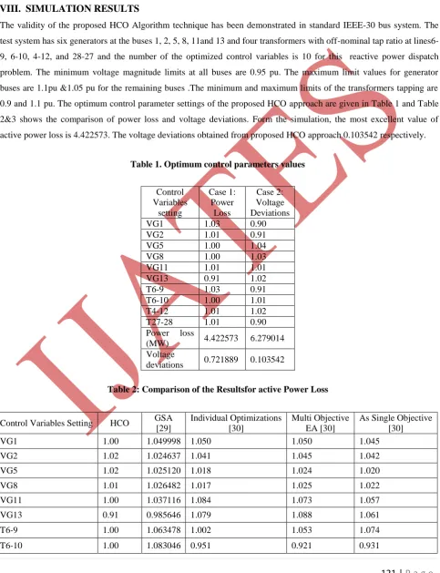
The validity of the proposed HCO Algorithm technique has been demonstrated in standard IEEE-30 bus system. The
test system has six generators at the buses 1, 2, 5, 8, 11and 13 and four transformers with off-nominal tap ratio at
lines6-9, 6-10, 4-12, and 28-27 and the number of the optimized control variables is 10 for this reactive power dispatch
problem. The minimum voltage magnitude limits at all buses are 0.95 pu. The maximum limit values for generator
buses are 1.1pu &1.05 pu for the remaining buses .The minimum and maximum limits of the transformers tapping are
0.9 and 1.1 pu. The optimum control parameter settings of the proposed HCO approach are given in Table 1 and Table
2&3 shows the comparison of power loss and voltage deviations. Form the simulation, the most excellent value of
active power loss is 4.422573. The voltage deviations obtained from proposed HCO approach 0.103542 respectively.
Table 1. Optimum control parameters values
Control Variables
setting
Case 1: Power
Loss
Case 2: Voltage Deviations
VG1 1.03 0.90
VG2 1.01 0.91
VG5 1.00 1.04
VG8 1.00 1.03
VG11 1.01 1.01
VG13 0.91 1.02
T6-9 1.03 0.91
T6-10 1.00 1.01
T4-12 1.01 1.02
T27-28 1.01 0.90
Power loss
(MW) 4.422573 6.279014
Voltage
deviations 0.721889 0.103542
Table 2: Comparison of the Resultsfor active Power Loss
Control Variables Setting HCO GSA
[29]
Individual Optimizations [30]
Multi Objective EA [30]
As Single Objective [30]
VG1 1.00 1.049998 1.050 1.050 1.045
VG2 1.02 1.024637 1.041 1.045 1.042
VG5 1.02 1.025120 1.018 1.024 1.020
VG8 1.01 1.026482 1.017 1.025 1.022
VG11 1.00 1.037116 1.084 1.073 1.057
VG13 0.91 0.985646 1.079 1.088 1.061
T6-9 1.00 1.063478 1.002 1.053 1.074
122 |
P a g e
T4-12 1.01 1.100000 0.990 1.014 1.019
T27-28 1.01 1.039730 0.940 0.964 0.966
Power Loss (Mw) 4.422573 4.616657 5.1167 5.1168 5.1630
Voltage Deviations 0.721889 0.836338 0.7438 0.6291 0.3142
Table 3: Comparison of the Resultsfor voltage deviations
Control Variables Setting HCO GSA
[29]
Individual Optimizations [30]
Multi Objective EA [30]
As Single Objective [30]
VG1 0.92 0.995371 1.009 1.016 1.021
VG2 0.90 0.950069 1.006 1.012 1.021
VG5 1.01 1.043033 1.021 1.018 1.021
VG8 1.01 1.021292 0.998 1.003 1.002
VG11 1.02 1.100000 1.066 1.061 1.025
VG13 1.02 1.062669 1.051 1.034 1.030
T6-9 0.90 0.905907 1.093 1.090 1.045
T6-10 1.00 1.035611 0.904 0.907 0.909
T4-12 1.03 1.038107 1.002 0.970 0.964
T27-28 0.91 0.925607 0.941 0.943 0.941
Power Loss (Mw) 6.279014 6.371609 5.8889 5.6882 5.6474
Voltage Deviations 0.103542 0.106498 0.1435 0.1442 0.1446
IX.
CONCLUSION
In this paper, theHCOhas been successfully implemented to solve Optimal Reactive Power Dispatch problem. The
proposed algorithm has been tested on the standard IEEE 30-bus system. Simulation results indicate the toughness of
projected HCO approach for providing better optimal solution in reducing the real power loss. The control variables
obtained after the optimization by HCO is within the limits.
REFERENCES
[1] O.Alsac,and B. Scott, “Optimal load flow with steady state security”,IEEE Transaction. PAS -1973, pp.
745-751.
[2] Lee K Y ,Park Y M , Oritz J L –A united approach to optimal real and reactive power dispatch , IEEE
Transactions on power Apparatus and systems 1985: PAS-104 : 1147-1153
[3] A.Monticelli , M .V.F Pereira ,and S. Granville , “Security constrained optimal power flow with post
contingency corrective rescheduling” , IEEE Transactions on Power Systems :PWRS-2, No. 1,
pp.175-182.,1987.
[4] DeebN ,Shahidehpur S.M ,Linear reactive power optimization in a large power network using the
123 |
P a g e
[5] E. Hobson ,‟Network consrained reactive power control using linear programming, „ IEEE Transactions on
power systems PAS -99 (4) ,pp 868=877, 1980
[6] K.Y Lee ,Y.M Park , and J.L Oritz, “Fuel –cost optimization for both real and reactive power dispatches” ,
IEE Proc; 131C,(3), pp.85-93.
[7] M.K. Mangoli, and K.Y. Lee, “Optimal real and reactive power control using linear programming” ,
Electr.PowerSyst.Res, Vol.26, pp.1-10,1993.
[8] C.A. Canizares , A.C.Z.de Souza and V.H. Quintana , “ Comparison of performance indices for detection of
proximity to voltage collapse ,‟‟ vol. 11. no.3 , pp.1441-1450, Aug 1996 .
[9] S.R.Paranjothi ,andK.Anburaja, “Optimal power flow using refined genetic algorithm”,
Electr.PowerCompon.Syst , Vol. 30, 1055-1063,2002.
[10]D. Devaraj, and B. Yeganarayana, “Genetic algorithm based optimal power flow for security enhancement”,
IEE proc-Generation.Transmission and. Distribution; 152, 6 November 2005.
[11]A.Berizzi, C. Bovo, M. Merlo, and M. Delfanti, “A ga approach to compare orpf objective functions including
secondary voltage regulation,” Electric Power Systems Research, vol. 84, no. 1, pp. 187 – 194, 2012.
[12]C.-F. Yang, G. G. Lai, C.-H. Lee, C.-T. Su, and G. W. Chang, “Optimal setting of reactive compensation
devices with an improved voltage stability index for voltage stability enhancement,” International Journal of
Electrical Power and Energy Systems, vol. 37, no. 1, pp. 50 – 57, 2012.
[13]P. Roy, S. Ghoshal, and S. Thakur, “Optimal var control for improvements in voltage profiles and for real
power loss minimization using biogeography based optimization,” International Journal of Electrical Power
and Energy Systems, vol. 43, no. 1, pp. 830 – 838, 2012.
[14]B. Venkatesh, G. Sadasivam, and M. Khan, “A new optimal reactive power scheduling method for loss
minimization and voltage stability margin maximization using successive multi-objective fuzzy lp technique,”
IEEE Transactions on Power Systems, vol. 15, no. 2, pp. 844 – 851, may 2000.
[15]W. Yan, S. Lu, and D. Yu, “A novel optimal reactive power dispatch method based on an improved hybrid
evolutionary programming technique,” IEEE Transactions on Power Systems, vol. 19, no. 2, pp. 913 – 918,
may 2004.
[16]W. Yan, F. Liu, C. Chung, and K. Wong, “A hybrid genetic algorithminterior point method for optimal
reactive power flow,” IEEE Transactions on Power Systems, vol. 21, no. 3, pp. 1163 –1169, aug. 2006.
[17]J. Yu, W. Yan, W. Li, C. Chung, and K. Wong, “An unfixed piecewiseoptimal reactive power-flow model and
its algorithm for ac-dc systems,” IEEE Transactions on Power Systems, vol. 23, no. 1, pp. 170 –176, feb.
2008.
[18]F. Capitanescu, “Assessing reactive power reserves with respect to operating constraints and voltage
stability,” IEEE Transactions on Power Systems, vol. 26, no. 4, pp. 2224–2234, nov. 2011.
[19]Z. Hu, X. Wang, and G. Taylor, “Stochastic optimal reactive power dispatch: Formulation and solution
method,” International Journal of Electrical Power and Energy Systems, vol. 32, no. 6, pp. 615 – 621, 2010.
[20]A.Kargarian, M. Raoofat, and M. Mohammadi, “Probabilistic reactive power procurement in hybrid electricity
markets with uncertain loads,” Electric Power Systems Research, vol. 82, no. 1, pp. 68 – 80, 2012.
[21]Jefferies D J, Deane J H B, Johnstone G G. An introduction to chaos [J]. Electronics & Communication
124 |
P a g e
[22]Wu X X, Chen Z. Introduction of chaos theory [J]. Shanghai Science and Technology Bibliographic
Publishing House, Shanghai, 1996.
[23]JIANG B L I W. Optimizing complex functions by chaos search [J]. Cybernetics & Systems, 1998, 29(4):
409-419.
[24]Liang H Y, Gu X S. A novel chaos optimization algorithm based on parallel computing [J]. Journal of East
China University of Science and Technology (Natural Science Edition), 2004, 30(4): 450-453.
[25]Wei T. Chaotic Optimization Method Based on Power Function Carrier and Its Applications [J]. Control
andDecision, 2005, 9: 016.
[26]YanguangCai, Jixin Qian, and Youxian Sun. The global optimized outlook algorithm [J]. Journal of
Guangdong University of Technology, 2006, 23(2):1-10.
[27]Shan L, Qiang H, Li J, et al. Chaotic optimization algorithm based on Tent map [J]. Control and Decision,
2005,20(2): 179-182.
[28]Xiaolan Wu and GuifangGuo, A hybrid global optimization algorithm based on parallel chaos optimization
and outlook algorithm, Journal of Chemical and Pharmaceutical Research, 2014, 6(7):1884-1889
[29]S.Duman,Y.Sonmez,U.Guvenc,N.Yorukeran ,” application of gravitational search algorithm for optimal
reactive power dispatch problem “ in IEEE trans on power system pp 519-523 , 2011 .
[30]M. A. Abido, J. M. Bakhashwain, “A novel multiobjectiveevolutionaryalgorithm for optimal reactive power
dispatch problem,” in proc.Electronics, Circuits and Systems conf., vol. 3, pp. 1054-1057, 2003.
Biographical Notes
K. Lenin has received his B.E., Degree, electrical and electronics engineering in 1999 from university of madras, Chennai, India and M.E., Degree in power systems in 2000 from Annamalai
University, TamilNadu, India. Presently pursuing Ph.D., degree at JNTU, Hyderabad,India.
Bhumanapally. RavindhranathReddy, Born on 3rd September,1969. Got his B.Tech in Electrical & Electronics Engineering from the J.N.T.U. College of Engg., Anantapur in the year
1991. Completed his M.Tech in Energy Systems in IPGSR of J.N.T.University Hyderabad in the
year 1997. Obtained his doctoral degree from JNTUA,Anantapur University in the field of
Electrical Power Systems. Published 12 Research Papers and presently guiding 6 Ph.D. Scholars.
He was specialized in Power Systems, High Voltage Engineering and Control Systems. His