NONLINEARITY IN OPTICAL SWITCHING
Shikha Jaiswal11. INTRODUCTIONTO OPTICAL SWITCHING
Explosive information demands capacity expansion in next generation telecommunication networks. It is expected that data– oriented network traffic will double every year.Optical networks are widely regarded as the ultimate solution to the bandwidth needs of future communication systems. Optical fiber links deployed between nodes are capable to carry terabits of information between electronic switching at the nodes limit the bandwidth of a network. Optical switches provide the key to manage Dense wavelength division multiplexing (DWDM) links as well as provision of newband width hungry services. Though the optical networks are challenged in terms of signal impairment and network related parameters.
2. ROLE OF NON-LINEARITY IN OPTICALSWITCHING
The terms linear and nonlinear in optics, means intensity independent and intensity dependent phenomena . Non linearity effects rise due to change in the refractive index of the medium with optical intensity and inelastic scattering phenomena. Non-linearity mainly occurs in optical fibers, semi-conducting materials in semiconductor optical amplifier (SOA), non-linear organic materials and other micro-optic devices.
The devices used for optical signal processing (OSP) are Vertical Cavity Surface Emitting Laser (VCSEL), Spatial Light Modulator (SLM), non-linear organic materials, optical fiber as a non-linear device, semi-conductor optical amplifier (SOA). [1]The role of nonlinear optics in optical switching has become extremely significant. Non-linear materials are those, which interact with light and modulate its properties. Several of the optical components require efficient nonlinear materials for their operations. The widespread use of all optical devices is restrained due to the inefficiency of currently available nonlinear materials.All optical computing functions are usually performed using non-linear optical effects that occur in a device under certain conditions.
Optical switch takes advantage of the way of the refractive index of glass changes as the intensity of light varies. Switching can be done using the nonlinearity effect introduced without SOA or with SOA. Optical gates without SOA using length of the fiber, waveguide, circulator, filters, acoustic-optic waves, and changing the refractive index of the optical waveguide have been discussed. [2].Nonlinearity can be induced by using length of fiber. Glass optical fibers experience non-linear effects, some of which can be used to design very fast switching elements, capable of changing their state in to second (quadrillionth of a second time scale).
1
Deptt of Physics, Feroze Gandhi College, Raebareli
DOI: http://dx.doi.org/10.21172/1.133.05
e-ISSN:2278-621X
Abstract- Optical computers are attractive for future broadband optical communication which needed flexible optical processing devices. Optical logic gates are key element of these devices. Now a days most long distances telephone and internet communication is carried on optical fibers and optical switching has several advantages like high speed, low heating and economically viable. Nonlinear materials have tendency to change the optical properties employing nonlinear Kerr effect. The SPM, XPM, FWM in optical fiber is discussed in context of nonlinearity. Semi-conductor Optical Amplifier in Mach Zehnder Interferometer Configuration (SOA-MZI) is reviewed for optical logic gates.The essential featuresof semiconductor optical amplifier in MZI and NMZIare reviewed here. An investigation of various parameters like insertion loss, extinction Ratio, crosstalk for NMZI is done. The I/O characteristics have been discussed for variation in nonlinear arm, nonlinear coefficients, wavelengths of input beam, offset. A thorough theoretical review of fundamentals of all-optical communication has been presented.
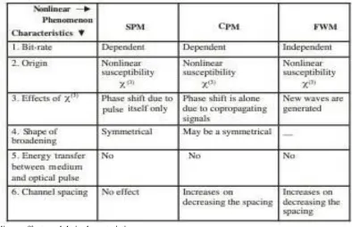
2.1 Self Phase Modulation (SPM)
SPM is a non linear optical effect of light matter interaction. An ultrashort pulse when travelling in a medium, will induce a varying refractive index of the medium due to optical Kerr effect. This variation in refractive index will produce a phase shift in the pulse, leading to change of the pulse frequency spectrum. The front of pulse is shifted to lower and back of pulse shifted to high frequency. Non linear phase modulation is self induced, therefore known as SPM. The different parts of pulse undergo different phase shift because of intensity dependence of phase fluctuations.SPM leads to chirping with lower frequency in the leading edge and higher frequency in the trailing edge. On the other hand, the chirping caused by linear dispersion, in the wavelength region above zero dispersion wavelength, is associated with higher frequency in the leading edge and lower frequency in trailing edge. Both these effects are opposite. By proper choice of pulse shape, one effect can be compensated with other. In such situation, the pulse will propagate undistorted by mutual compensation of dispersion and SPM. Such a pulse will broaden neither in time domain nor in frequency domain and is called Soliton. [3]
Fig 1 Self Phase Modulation
2.2 Cross Phase Modulation (CPM)
SPM is the major nonlinear limitation in single channel system. The intensity dependence of refractive index lead to another nonlinear phenomena known as CPM or XPM. The cross phase modulation is always accompanied by SPM and occurs because the nonlinear refractive index seen by an optical bean depends not only on the intensity of that beam but also on the intensity of other copropagating beam [4]. The results of XPM may be asymmetric spectral broadening and distortion of the pulse shape.
Table 1. Nonlinear effects and their characteristics.
n eff .= n l + n nl (P/A eff.) (1.1)
Where P is input power and A eff. is effective core area.
If the first order perturbation theory is applied to investigate how fiber modes are affected by nonlinear refractive index, it is found that the mode shape does not change but the propagation constant k becomes power dependent.
CPM influences the system severely when number of channels is
2.3 Four Wave Mixing (FWM)
The origin of FWM process lies in the nonlinear response of boundedelectrons of a material to an applied optical field. In fact, the polarization induced in the medium contains not only linear terms but also nonlinear terms. The magnitude of these terms is governed by the nonlinear susceptibility of different orders. The FWM process originates from third order nonlinear susceptibility. If three optical fields with carrier frequencies ω1 ,ω2 ,ω3 copropagate inside the fiber simultaneously, generates a fourth field with frequency ω4 which is related to other frequencies by a relation ω4=ω1±ω2±ω3. In quantum mechanical context,FWM occurs when photons from one or more waves are annihilated and new photons are created at different frequencies such that net energy and momentum are converted during the interaction. SOAs are playing a significant role in optical integrated circuits. A number of their advantages, wide gain spectrum, possibilities of integration with other devices are making them very attractive not only for amplifying the signal but also for all optical data processing like in wavelength converters where SOA's provide XPM. [5].
The nonlinear behavior of a SOA originates from carrier depletion at high optical input powers. This changes both the gain and the refractive index (thus optical phase) in SOA. For using them in nonlinear applications, high values of phase change should accompany low changes in gain. The comparison between these two is defined as α factor or linewidth enhancement factor. The input coupler is unbalanced, so that the power differences over the branches of MZI are obtained. The output of MZI then depends both on the „gain saturation‟ and „phase shift‟ due to SPM in SOA. Analyzing the output signal gives information on α factor. By sweeping the input power at ports 1 and 2 over a large range, measuring the output power at port 3, the overall gain of MZI was determined.
2.4 All-Optical Gates with SOA.
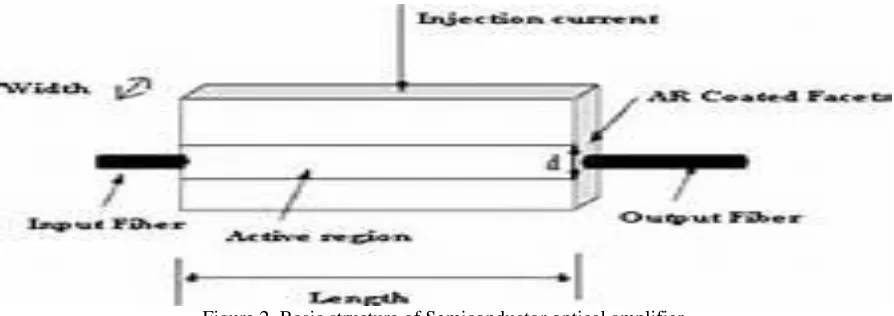
Figure 2. Basic structure of Semiconductor optical amplifier.
The gates are divided according to the interferometer techniques such as ultra-high nonlinear interferometer (UNI), sagnac interferometer (SI), Michelson interferometer(MI), Mach-Zehnder interferometer (MZI), and delay interferometer (DI) to implement the nonlinearity in SOA. In the following sections the nonlinearity of SOA may be used in several ways. SOA is a small size nonlinear amplifier that offers advantages to be integrated to produce a subsequent system essential in optical communication system. The SOAs exhibit low power consumption and their single mode waveguide structures make them particularly appropriate for use with single mode fiber[3].At present, SOA is the most developed optical amplifier that makes a rapid progress towards optical signal processing. The nonlinearity effect in SOA makes it a promising module for optical logic gates. The three nonlinearity effects that is cross gain modulation (XGM), cross phase modulation (XPM), and four wave mixing (FWM) make it possible to use it as nonlinear medium for gates. The most inconvenient feature is the slow response associated with carrier recombination.
3. SOA-MZI
The interferometer configuration may be defined in two ways, copropagation and counterpropagation. In copropagation, filter is required because pump and probe travel in the same direction to filter the probe signal with pump. But in counter propagation both travel in opposite directions, so the filter is not required.
modulation. This can be done by SOA, incorporated with interferometer configuration. To obtain a complete extinction in an interferometer a phase shift of� is needed which can be achieved with gain compression in SOA. The phase shift is independent of wavelength, so the conversion to a longer wavelength has no problem with XPM.
Some important works on optical computing devices based on SOA-MZI are: parity checking and generating circuit with SOA in all optical domain[6] performance analysis of all optical NOR gate at 80 Gbps [7]ultrafast all optical 4 bit digital encoders using differential phase modulation SOA-MZI [8] all-optical error detection circuit using SOA-MZI based XOR gate [8] quantum dot SOA-MZI based high-speed gates[9] anddata format conversions based on SOA-MZI have been reported.[10]
The disadvantage of an interferometer structure is that if the phase shift increases more than �, it impairs the extinction ratio which may be controlled by changing the bias condition of SOA. In FWM two signals of different wavelengths are injected into the SOA .On passing through SOA there is an intensity beating which arises due to the difference in frequency modulated signals in SOA. If the frequency separation is small the carrier density will be modulated. If the frequency separation is large, the modulated carrier will set up a moving grating in the active strip of SOA. The grating scatters the input signal and produces the sidebands which are located at the lower and higher frequency between the input signals. The power of the side bands is usually less as compared to the signal power. It is a process which depends on the phase of the optical signal instead of their intensity. It is a polarization dependent phenomenon and capable of handling intensity modulation, phase modulation,and frequency shift keying signal. A shift depends upon distance between the signals and converted wavelengths, therefore the conversion efficiency is adequately affected. Therefore the scheme is not used in all-optical network. The application of FWM is used in dispersion management by all-optical phase conjugate. The process produces a mirror image of the original signal which is oppositely chirped in a spectral domain.
4. SOA-NMZI
One of the top listed and extensively investigated components for optical devices is Mach-Zehnder interferometer (MZI) [A Srivastava, S Medhekar 2011][11]. When MZI is fabricated with one of its arm made of a nonlinear material, it becomes an all-optical switching device and is called as nonlinear Mach-Zehnder interferometer (NMZI). NMZI using the optical Kerr effect is more suitable for faster transmission systems due to its ultrafast response. NMZI structure has also been investigated for all optical logic [ T Yabu, M Geshiro, T Kiyamura, K Nishida, S Sawa2002][12] [S Medhekar, P P Paltani 2009][13] due to its application in telecommunication systems. All-optical AND gate can perform the bit level functions like packet-header modification, data integrity verification and address recognition. The all-optical XOR gate is a key technology to implement primary systems for binary address and header recognition, binary addition and counting, decision and comparison, encoding and encryption, and pattern matching.
An ultrashort pulse is the input through channel 1 of the device, whereas the other input channel 2 receives no light. The pulse has a hyperbolic secant shape. The study was based on the analysis of power transmission, extinction ratio focussing on channel 4 of the output device.
The extinction ratio of a switching on-off device isto be calculated as the output power in on state (channel 4) over the output power in off state (channel 3) or vice versa.
The cross talk (XTalk) denotes the presence of an unwanted signal due to some coupling mechanism between the disturbed and disturbing channels. For a proper device operation, XTalk must be keep at minimum.
5. OBSERVATIONS
5.1 Switching behaviour with varying wavelength
The different nonlinearity profiles enable different behaviours in output, thus the profile is to be chosen which best fits each application (such as switching, filters in WDM system, logic gates, all optical logic systems etc.The switching occurs at lower intensity if the wavelength of the input is decreased.
5.2 Effect of change of offset on switching behaviour
For a low intensity input, whole input launched at port P1, appears at port P4 leaving zero output at port P3. It is called as zero offset conditionThe offset of a NMZI can be changed by slightly changing the linear refractive index of one of the two arms. Change of offset is an attractive feature as it offers adjustment of operating powers of a NMZI device.
6. CONCLUSION
The benefits of all optical are been studied thoroughly. The SOA-MZI structure is studied and reviewed for its application in all optical computing. The essential features of semiconductor optical amplifier in MZI and NMZI are reviewed here and dependence of various parameters like insertion loss, extinction Ratio, crosstalk for NMZI is optimized. The I/O characteristics have been discussed for variation in nonlinear arm, nonlinear coefficients, wavelengths of input beam, offset.
7. REFERENCES
[1] G.P.Aggarwal , “Nonlinear fiber optics” Academic press 2007.
[2] Pallavi Singh, D.K.Tripathi, Shikha Jaiswal, H.K.Dixit“All-Optical LogicGates: Designs, Classification, andComparison”.Advancesin Optical technologies 2014, pp.1-13
[3] Shikha Jaiswal,” SOA: A competent device for all optical computing”, ISST JEEE Vol 8 No july- dec 2017 pp 5-9
[4] Pallavi Singh, D.K.Tripathi, Shikha Jaiswal, H.K.Dixit, “Design and analysis of all optical AND, XOR and OR gates based on SOA-MZI”, Optics and Laser Technology, 66 (2015) 35-44
[5] Rekha Mehra, Shikha Jaiswal, H.K.Dixit, “Optical computing with SOA”, Optical Engineering 51(8) 2012, 1-7.
[6] Rekha Mehra, Shikha Jaiswal, H.K.Dixit, Pallavi Singh “Performance analysis of all optical NOR gate at 80 Gbps”, Optik 124(2013) 1672-75. [7] Rekha Mehra, Shikha Jaiswal, H.K.Dixit, “Parity checking and generating circuit with SOA in all optical domain”, Optik 124 (2013) 4744-45. [8] Rekha Mehra, Shikha Jaiswal, H.K.Dixit, “Ultrafast all optical 4 bit digital encoders using differential phase modulation in SOA-MZI configuration,
Optical Engineering 52(3), 1-5
[9] S.Ma et al, “High speed all optical gates based on quantum dot SOA” -Opt. Express. 18(7), 6417-6422,2010.
[10] S.Singh, J.singh and S.Singh Gill, “ Investigation of data format conversion based on MZI-SOA” -Opt. Lasers Eng. 49(1), 152-158 (2011). [11] J.D.Juannopoulos, P.R.Villeneuve, S Fan, “PhotonicCrystals ; putting a new twist on light”, Nature, Vol.386, 1997..
[12] T.Baba.,(Eds.) Roadmap of Photonic Crystal, Kluwer Academic, 2003.