Systematic evaluation of square patch
antenna performance based on
permittivity of the material
1
D.Rakesh, 2P.Rakesh Kumar, 1*B.T.P.Madhav, 1Prof. Habibulla Khan 1K Ch Sri Kavya,
1
K.Prabhu Kumar, 1S Bala Durga Prasad
1
Department of ECE, K L University, Guntur DT, AP, India
2
Assistant Professor, Department of ECE, LBRCE (Autonomous), Mylavaram, AP, India
Abstract
People are attracting towards the usage of small and compact antennas in the present day scenario. Small and portable devices are gaining their importance in the communication technology. Patch antennas are one of the most attractive antennas for integrated RF front-end systems due to their compatibility with microwave integrated circuits. To fulfill the demand of integrated RF front-end systems, a design of micro strip patch antenna for 60GHz microwave applications has been introduced. This antenna maintains a maximum gain of 7.91dB for far field region with respect to paraboloidal rectangular aperture antenna. It is actually a coaxial probe fed antenna for impedance matching with 50 ohms coaxial cable. This antenna works well in the frequency 60GHz with a maximum at 60.15GHZ. It is basically a low cost, light weight, medium gain and narrow band antenna for microwave applications such as a feeding element for other antennas and in research institutes as a reference antenna. It can also be used at the output of signal conditioning circuit for receiving signals from micro electromechanical sensors.
Keywords: Square patch, substrate materials.
Introduction:
Communication using electromagnetic radiation (expect for light) began early in last century. Most of the early systems used very long wavelengths (low frequencies), which travelled great distances. Later it was discovered that higher frequencies could bring other advantages to communications. Microwaves are easier to control (than longer wavelengths) because even small antennas could direct the waves very well. This control leads to confinement of energy into a tight beam (expressed as narrow beam width). This beam can be focused on another antenna dozens of miles away, making it very difficult for someone to intercept the conversation.
Microwaves are commonly used in various aspects of everyday life. At microwave frequencies the physical size of high gain antenna becomes small enough to make practical the use of suitably shaped reflectors to produce the desired directivity [1]. Nowadays for various commercial applications such as short range transmission of signals, medical applications, mobiles and laptops there is requirement of an antenna which consumes very less space and can be mounted easily in the equipment and still have efficient directive radiation pattern. One such antenna design, which is very famous these days, is micro strip patch antenna [2].
Micro strip antennas have been used in many civilian and government applications despite of their advantages and disadvantages. Sometimes disadvantages are counted as advantage e.g., for narrow band applications the antenna itself can act as a filter for unwanted frequency components, so small bandwidth is counted as an advantage. Micro strip antennas include Wireless Personal Area Network (WPAN) and good performance in antenna technology and low cost. Different techniques have been suggested to achieve antenna integration within a single chip [3].
Design considerations:
A micro strip antenna in its simplest form consists of a sandwich of two parallel conducting layers separated by a single thin dielectric substrate. The lower conductor functions as a ground plane and the upper conductor functions as radiator [5]. The simplest patch antenna uses a half wavelength long patch and a larger ground plane. Larger ground plane gives better performance but of course makes the antenna bigger. Among different shapes of micro strip patch elements such as rectangular, square, dipole, triangular, circular and elliptical for better radiation characteristics we use rectangular micro strip patch antenna. The resonant length of the antenna determines the resonant frequency [6]. The patch is in fact electrically a bit larger than its physical dimensions due to the fringing fields. The deviation between electrical and physical size is mainly dependent on the PCB thickness and dielectric constant. The patch that introduced here has been made of conducting material copper. The design parameters define the operation and performance of the patch antenna [7]. In this paper the patch dimensions taken along X-axis and Y-axis is 0.15 cm and the substrate dimensions taken along X-axis and Y-axis is 1 cm respectively. The substrate thickness is 0.03 cm. The feed location along X and Y axis are 0 and 0.05 respectively. The coaxial inner and outer radius is 0.004 and 0.014 respectively and coaxial feed length is 0.04 cm. For good performance, a substrate having a low dielectric constant is desirable since this provides better efficiency, larger bandwidth and better radiation.
The design also checks for maximum power transfer by matching the feed line impedance to the impedance of the patch antenna [8]. The different feeding techniques used for impedance matching are micro strip line, coaxial probe, Proximity coupling and aperture coupling. Micro strip line: In this Impedance matching is easier. And feed can be fabricated on some substrate as single layer to provide planner structure. But disadvantage is we must use transformer to match impedance and it excites cross polarization. Coaxial probe: Probe location is used for impedance matching. Ease of insetting and low radiations is advantages of probe feeding. Proximity coupling: Proximity coupling offers some opportunity to reduce feed line radiation while maintaining a relatively thick substrate for the radiating patch [9]. The input impedance of antenna is affected by the overlap of the patch and the feed line, and by the substrates. However due to multilayer fabrication the antenna thickness increases. Aperture coupling: No spurious radiation escapes to corrupt the side lobes or polarization of the antenna. However due to multilayer fabrication antenna, thickness increases [10].
Among this coaxial probe is used for impedance matching, as it is ease of insetting and low radiation and also used with plated for multi layer circuits. Micro strip antennas are versatile in the sense that they can be designed to produce a wide variety of patterns and polarizations, depending on the mode excited and the particular shape of the patch used [11].
Substrates:
Simulation results:
Figure (1) Ansoft-HFSS Generated Square patch model
Figure (1) shows the Ansoft-HFSS generated model for microstrip square patch array antenna. Different substrate materials are considered and simulated by placing them on the proposed model at 60GHz. The table (1) shows the physical parameters of different substrate materials.
Substrate
material
Dielectric
constant
(Єr)
Frequency fr
(GHz)
Effective dielectric
constant (Єeff)
Loss tangent value
(δ)
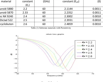
RT‐Duroid‐5880 2.2 60 2.1144 0.0011
RT‐Duroid‐5870 2.33 60 2.2352 0.0011
Neltec NX 9240 2.4 60 2.3002 0.0010
Arlon Diclad 522 2.5 60 2.3931 0.0010
Benzocyclobuten 2.6 60 2.4859 0.0010
Table (1) Substrate materials with Permittivity
Figure (2) Return loss
Figure (3) VSWR graph
The VSWR<2 is obtained at the resonant frequency and the VSWR values for different dielectric constants 2.2, 2.33, 2.4, 2.5, 2.6 are 1.41, 1.47, 1.51, 1.55, 1.59 respectively.
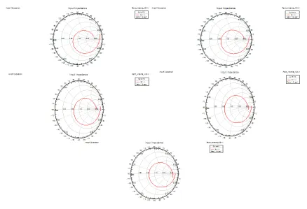
Input impedance smith chart:
S.NO For Єr=2.2,
δ=0.001
1
For Єr= 2.33,
δ=0.0011
For Єr= 2.4,
δ=0.001
0
For Єr= 2.5,
δ=0.001
0
For Єr= 2.6,
δ=0.00
10
1 rms value 0.6182 0.6123 0.6117 0.6129 0.6163
2 Gain margin 14.838 14.037 13.615 13.100 12.664
3 Phase margin 192.32 188.39 186.09 182.81 179.33
4 Gain cross over 45.00 45.00 45.00 45.00 45.00
5 Phase cross over 61.29 59.79 59.00 57.95 56.94
6 Upper cut off 53.66 52.40 51.76 50.91 50.10
7 Band width 53.66 52.40 51.76 50.91 50.10
Table (2) Input impedance parameters
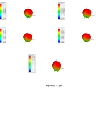
Figure (4) gives the input impedance smith chart for the different cases of square patch with respect to different substrate materials. The parameters simulated from the smith chart curve are tabulated in the table (2). Figure (5) and (6) shows the 3D and 2D gains for the proposed model with different dielectric constant values. The maximum 2D gain values obtained for dielectric constants 2.2, 2.33, 2.4, 2.5 and 2.6 are 7.91, 7.81, 7.77, 7.67 and 7.58 dB respectively. A gain of more than 7dB is obtained at each case and this is showing a good agreement for the applicability of the antenna for these materials. The maximum directivity values obtained for dielectric constants 2.2, 2.33, 2.4, 2.5 and 2.6 are 6.21 at 900, 6.08 at 900, 6.01 at 950, 5.90 at 950 and 3.76 at 900 respectively.
Figure (6) 2D-gain
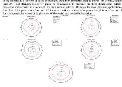
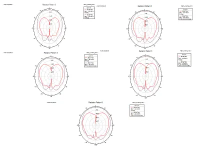
Radiation pattern is a mathematical function or graphical representation of the radiation properties of the antenna as a function of space coordinates. Radiation properties include power flux density, radiation intensity, field strength, directivity phase or polarization. In practice, the three dimensional pattern is measured and recorded in a series of two dimensional patterns. However for most practical applications, a few plots of the pattern as a function of θ for some particular values of φ, plus a few plots as a function of φ for some particular values of θ, give most of the useful and needed information.
Figure (7) Radiation patterns of gain phi at 00
Radiation patterns of gain theta at 00
and 900
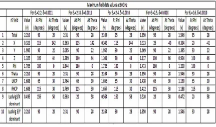
Antenna parameters and maximum field data are simulated from the Ansoft-HFSS and they are tabulated in table (3) and table (4).
Antenna parameters at 60GHz
For Єr=2.2,
δ=0.001
1
For Єr=2.33,
δ=0.001
1
For Єr=2.4,
δ=0.001
0
For Єr=2.5,
δ=0.001
0
For Єr=2.6,
δ=0.001
0
1 Max U 0.00648w/sr 0.0070 w/sr 0.0062 w/sr 0.0045 w/sr 0.0031 w/sr
2 Peak Directivity 6.214 6.086 6.013 5.900 5.771
3 Peak gain 6.1814 6.0482 5.9911 5.8621 5.7365
4 Peak realized gain 5.7134 5.7813 5.676 5.336 4.884
5 Radiated power 0.0131 w 0.0146 w 0.0129 w 0.0096 w 0.0069 w
6 Accepted power 0.0131 w 0.0147 w 0.0130 w 0.0097 w 0.0069 w
7 Incident power 0.0142 w 0.0153 w 0.0137 w 0.0106 w 0.0081 w
8 Radiation efficiency 0.9946 0.9937 0.9962 0.9934 0.9939
9 Front to back ratio 23.765 24.085 24.971 24.462 24.51
Table (4) Maximum field data
Conclusion:
Performances of microstrip square patch antenna based on different substrate materials are investigated and their performance characteristics are shown and tabulated in this present work. We observed that the by increasing the dielectric constant of the substrate material the bandwidth is decreasing and gain values are decreased. We also observed that the maximum directivity also decreased by increasing the permittivity of the substrate materials. This present work carries the measurement of antenna parameters for different substrate materials. The return loss and VSWR are also showing good agreement with the theoretical values for the proposed model.
Acknowledgments:
The authors like to express their thanks to the department of ECE, K L University for their moral encouragement and support during this work.
References:
[1] Constantine A. Balanis; Antenna Theory, Analysis and Design, John Wiley & Sons Inc. 2ndedition. 1997.
[2] Y.T. Lo. and S.W. Lee, editors, Antenna Handbook Theory, Applications and Design, Van Nostrand Reinhold Company, New York, 1988.
[3] Stutzman Warren L. and Thiele Antennas and propagation Magazine, vol.52, Feb 2010)
[4] Measuring the Impedance of balanced antennas by an S-parameter method. (IEEE Antennas and propagation Magazine, vol.52, Feb 2010)
[5] D.M. Pozar and D.H. Schaubert, editors, Microstrip Antennas: The Analysis and Design of Micro strip Antennas and Arrays, pp. 53, IEEE Press, 1995.
[6] Design inset-fed Micro strip Patch Antennas. May 26 2008 [online] Available:
http://www.mwrf.com/Articles/ArticleID/6993/6993.html.
[7] Hirasawa K and Haneishi M., Analysis, Design and Measurement of Small and Low'Profile Antennas, Artech House, Norwood, MA, 1992.
[8] D. Orban and G.J.K Moernaut, “The Basics of Patch Antennas”, RF Globalnet, 31 August 2005. Avaialbale online on 15 June 2008 on www.orbanmicrowave.com/The_Basics_Of_Patch_Antennas.pdf,
[9] R. Garg, P. Bhartia, I. Bahl, A. Ittipiboon, “Micro strip Antenna Design Handbook”. Artech House, Inc. Norwood, MA. 2001. Gary A. Antenna Theory and Design. John Wiley & Sons. Inc. New York, 1998.
[10] Multi-Band configurations of stub-loaded slotted rectangular micro strip antennas (IEEE paper)
[11] R. Garg, P. Bhartia, I. Bahl, A. Ittipiboon, “Microstrip Antenna Design Handbook”. Artech House, Inc. Norwood, MA. 2001. [12] Robert A. Sainati, CAD of Microstrip Antennas for Wireless Applications, Artech House Inc, Norwood, MA, 1996.
[13] M. Olyphant, Jr. and T. E. Nowicki, “Microwave substrates support MIC technology,” Microwaves, Part I, vol. 19, no. 12, pp. 74-80, Nov. 1980.
[14] Design inset-fed Microstrip Patch Antennas. May 26 2008 [online] Available:
B.T.P.Madhav was born in India, A.P, in 1981. He receieved the B.Sc, M.Sc, M.Tech, MBA degrees from Nagarjuna University, A.P, India in 2001, 2003, 2007, 2009 respectively. From 2003-2007 he worked as lecturer and from 2007 to till date he is working as Asst.professor in Electronics Engineering. He has published more than 25 papers in International and National journals. His research interests include antennas, liquid crystals applications and wireless communications.