DYNAMIC VIRTUAL NETWORK RESTORATION WITH OPTIMAL STANDBY VIRTUAL ROUTER SELECTION
A Dissertation IN
Telecommunication & Computer Networking and
Mathematics
Presented to the Faculty of the University of Missouri–Kansas City in partial fulfillment of
the requirements for the degree DOCTOR OF PHILOSOPHY
by XUAN LIU
M.S., University of Missouri–Kansas City, USA, 2010 B.S., China University of Geosciences, Wuhan, Hubei, China, 2007
Kansas City, Missouri 2015
c
2015
XUAN LIU
DYNAMIC VIRTUAL NETWORK RESTORATION WITH OPTIMAL STANDBY VIRTUAL ROUTER SELECTION
Xuan Liu, Candidate for the Doctor of Philosophy Degree University of Missouri–Kansas City, 2015
ABSTRACT
Network virtualization technologies allow service providers to request partitioned, QoS guaranteed and fault-tolerant virtual networks provisioned by the substrate network provider (i.e., physical infrastructure provider). A virtualized networking environment (VNE) has common features such as partition, flexibility, etc., but fault-tolerance requires additional efforts to provide survivability against failures on either virtual networks or the substrate network.
Two common survivability paradigms are protection (proactive) and restoration (reactive). In the protection scheme, the substrate network provider (SNP) allocates re-dundant resources (e.g., nodes, paths, bandwidths, etc) to protect against potential failures in the VNE. In the restoration scheme, the SNP dynamically allocates resources to restore the networks, and it usually occurs after the failure is detected.
In this dissertation, we design a restoration scheme that can be dynamically imple-mented in a centralized manner by an SNP to achieve survivability against node failures in the VNE. The proposed restoration scheme is designed to be integrated with a pro-tection scheme, where the SNP allocates spare virtual routers (VRs) as standbys for the virtual networks (VN) and they are ready to serve in the restoration scheme after a node failure has been identified. These standby virtual routers (S-VR) are reserved as a shared-backup for any single node failure, and during the restoration procedure, one of the S-VR will be selected to replace the failed VR. In this work, we present an optimal S-VR se-lection approach to simultaneously restore multiple VNs affected by failed VRs, where these VRs may be affected by failures within themselves or at their substrate host (i.e., power outage, hardware failures, maintenance, etc.). Furthermore, the restoration scheme is embedded into a dynamic reconfiguration scheme (DRS), so that the affected VNs can be dynamically restored by a centralized virtual network manager (VNM).
We first introduce a dynamic reconfiguration scheme (DRS) against node failures in a VNE, and then present an experimental study by implementing this DRS over a realistic VNE using GpENI testbed. For this experimental study, we ran the DRS to restore one VN with a single-VR failure, and the results showed that with a proper S-VR selection, the performance of the affected VN could be well restored. Next, we proposed an Mixed-Integer Linear Programming (MILP) model with dual–goals to optimally select S-VRs to restore all VNs affected by VR failures while load balancing. We also present a
heuristic algorithm based on the model. By considering a number of factors, we present numerical studies to show how the optimal selection is affected. The results show that the proposed heuristic’s performance is close to the optimization model when there were sufficient standby virtual routers for each virtual network and the substrate nodes have the capability to support multiple standby virtual routers to be in service simultaneously. Finally, we present the design of a software-defined resilient VNE with the optimal S-VR selection model, and discuss a prototype implementation on the GENI testbed.
APPROVAL PAGE
The faculty listed below, appointed by the Dean of the School of Graduate Studies, have examined a dissertation titled “Dynamic Virtual Network Restoration with Opti-mal Standby Virtual Router Selection,” presented by Xuan Liu, candidate for the Doctor of Philosophy degree, and certify that in their opinion it is worthy of acceptance.
Supervisory Committee
Deep Medhi, Ph.D., Committee Chair
Department of Computer Science & Electrical Engineering Kamel Rekab, Ph.D.
Department of Mathematics and Statistics Baek-Young Choi, Ph.D.
Department of Computer Science & Electrical Engineering Ken Mitchell, Ph.D.
Department of Computer Science & Electrical Engineering Praveen Rao, Ph.D.
Department of Computer Science & Electrical Engineering James P.G. Sterbenz, Ph.D.
Information and Telecommunication Technology Center, The University of Kansas, Lawrence, KS 66045, USA
School of Computing and Communications, Lancaster University, Lancaster LA1 4WA, UK
Computing Department, The Hong Kong Polytechnic University, Hung Hom, Kowloon, Hong Kong
CONTENTS ABSTRACT . . . iii ILLUSTRATIONS . . . x TABLES . . . xiii ACRONYMS . . . xiv ACKNOWLEDGEMENTS . . . xvii Chapter 1 INTRODUCTION . . . 1
1.1 Network Virtualization: A Historical View . . . 1
1.2 Virtualized Network Environment . . . 7
1.3 Failure Types and Fault-Tolerance Schemes . . . 17
1.4 Problem Definition . . . 19
1.5 Contribution of the Dissertation . . . 22
1.6 Additional Collaboration and Projects . . . 25
1.7 Outline of the Dissertation . . . 32
2 LITERATURE SURVEY . . . 33
2.1 Survivable Optical Networks . . . 34
2.2 Survivable Virtual Network Embedding . . . 35
2.3 Autonomic Network Management . . . 38
3 DYNAMIC RECONFIGURATION SCHEME IN A VNE . . . 42
4 AN EXPERIMENTAL STUDY ON GPENI-VNI . . . 47
4.1 A Detailed View of the DRS . . . 47
4.2 Experimental Platform: GpENI-VINI Testbed . . . 50
4.3 Experimental Design . . . 55
4.4 Results Discussion . . . 61
4.5 Summary . . . 66
5 OPTIMAL STANDBY VIRTUAL ROUTER SELECTION MODEL . . . 69
5.1 Problem Formulation . . . 69
5.2 Heuristic Algorithm . . . 80
5.3 Experimental Design . . . 84
5.4 Results Discussion . . . 88
5.5 Summary . . . 108
6 PROTOTYPE DESIGN AND IMPLEMENTATION ON GENI . . . 110
6.1 Framework Design . . . 110
6.2 Proof of Concept . . . 115
6.3 Summary . . . 125
7 CONCLUSION AND FUTURE WORK . . . 126
7.1 Conslusion . . . 126
7.2 Future Work . . . 128
Appendix A Resource Specification (RSpec) in GENI . . . 130
A.1 Advertisement RSpec . . . 130
A.2 Request RSpec . . . 133
A.3 Manifest RSpec . . . 134
B Optimal S-VR Selection Model in AMPL . . . 135
REFERENCE LIST . . . 141
ILLUSTRATIONS
Figure Page
1 An Example of Virtual LANs . . . 3
2 An Example of Two VPNs over the Public Backbone Network . . . 4
3 An Example of Overlay Network . . . 6
4 Virtual Network Management Business Roles . . . 13
5 An Example of Virtual Network Environment . . . 14
6 Path/Link Protection Scheme . . . 19
7 A System View of the Problem Definition . . . 21
8 Time to Generate the XORP Configuration File within a Single Slice [79] 27 9 Time to Generate the XORP Configuration Files for Multiple Slices [79] . 28 10 Dynamic Reconfiguration Scheme for Virtual Networks . . . 43
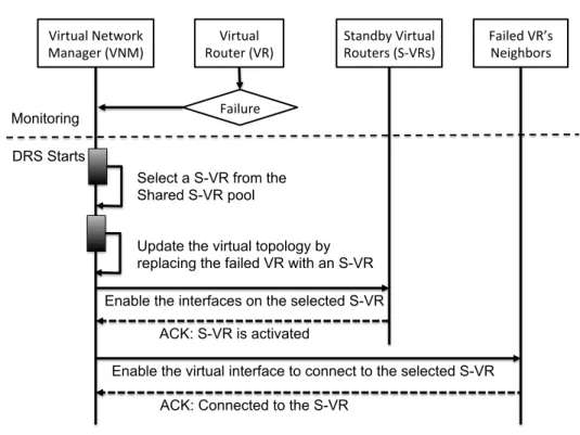
11 Sequence Diagram for the DRS . . . 48
12 GpENI Topology and Infrastructure in US, European and Asian Countries [6, 79] . . . 52
13 GpENI-VINI Architecture Overview [29, 79] . . . 53
14 Five-node and Nine-node Wide Area Virtual Topologies . . . 56
15 Geolocation-Based Strategy on Topology-I(a) . . . 62
16 Random Selection Method on Topology-I(a): TCP Session . . . 63
18 Geolocation-Based Method on Topology-II . . . 66
19 Two Scenarios on Virtual Interface Operations . . . 78
20 Three Topologies . . . 85
21 Abilene: Independent VR Failures (Cost v.s. Failures) . . . 89
22 Abilene: Regression Analysis on Cost v.s. Failures . . . 89
23 Nobel-EU: Independent VR Failures (Cost v.s. Failures) . . . 91
24 Germany50: Independent VR Failures (Cost v.s. Failures) . . . 91
25 Impact ofwa(Abilene Network): 4 S-VRs per VN . . . 93
26 Impact of wb (Abilene Network): 4 S-VRs per VN (wa = h0.2,0.8i, ji,k ∈(0,0.01). . . 96
27 Impact of wb (Abilene Network): 4 S-VRs per VN (wa = h0.8,0.2i, ji,k ∈(0,0.01). . . 97
28 Abilene: Independent VR Failures (L-BW: Low Bandwidth Request; H-BW: High Bandwidth Request) . . . 98
29 Nobel-EU: Independent VR Failures (L-BW: Low Bandwidth Request; H-BW: High Bandwidth Request) . . . 99
30 Germany: Independent VR Failures with L-BW Requests (Composite Im-pact of MNC and LB Objectives) . . . 103
31 Germany50: Independent VR Failures with L-BW Requests (Impact of the size of S-VR pool andhi) . . . 104
32 A Life-Cycle for Autonomic Virtual Network Management . . . 111
34 Structure of the Configuration File forScaleUpTool . . . 118
35 Configuration for VRs and End-Host Nodes with theScaleUpTool . . . 119
36 Determine Virtual Link Type with theScaleUpTool: An Example . . . 120
37 Node and Link Segments in a Request RSpec . . . 121
38 Preliminary Setup . . . 124
39 Node Section Schema of the A-RSpec . . . 131
40 Link Section Schema of the A-RSpec . . . 132
TABLES
Tables Page
1 Comparison table of Testbed supporting VNE . . . 15
2 GpENI-VINI Node Information . . . 57
3 End-to-End Round Trip Time . . . 59
4 Substrate Network Model Entities . . . 70
5 Virtual Network Model Entities . . . 71
6 Indicator & Cost Parameters . . . 71
7 Variables . . . 71
8 Weight Parameters . . . 72
9 Experimental Scenarios (10 VNs in a VNE) . . . 87
10 waValues (wθ =h0,1i,wb =h1,0i) . . . 92
11 wbValues (wθ =h0,1i,wa=h0.2,0.8iandh0.8,0.2i) . . . 95
12 Dependent VR Failures with Nobel-EUTopology (hi = 3) Worst Case: One Substrate Node Failure Affected all 10 VNs . . . 105
13 Computation Time: Nobel-EUwith 50 VNs (8 S-VRs per VN;hi = 3) . . 106
14 VNE under GENI Context . . . 117
ACRONYMS ATMAsynchronous Transfer Mode
AL2SAdvanced Layer-2 Service CDNContent Delivery Network
DRSDynamic Reconfiguration Scheme EGREEthernet GRE
GENIGlobal Environment for Network Innovations GpENIGreat Plain Environment for Network Innovation GREGeneric Routing Encapsulation
HTTPHypertext Transfer Protocol ICNInformation Centric Networking IIASInternet in a Slice
ILPInteger Linear Programming ISPInternet Service Provider
KVMKernel-based Virtual Machine LANLocal Area Network
LBLoad Balancing
L2TPLayer 2 Tunneling Protocol
MILPMixed Integer Linear Programming MNCMinimum Network Cost
MPLSMultiprotocol Label Switching MPMMultipath Measure
NATNetwork Address Translation
OFELIAOpenFlow in Europe: Linking Infrastructure and Applications OSPFOpen Shortest Path First
OXCOptical ross-connect
PPTPPoint-to-Point Tunneling Protocol QoSQuality of Service
QoEQuality of Experience
ROADMReconfigurable Optical Add-Drop Multiplexer RSpecResource Specification
RTTRound-Trip Time
SeRViTRSecure and Resilient Virtual Trust Routing SDHSynchronous Digital Hierarchy
SDNSoftware-Defined Networking SNSubstrate Network
SNPSubstrate Network Provider
SONETSynchronous Optical Networking SSHSecure Shell
S-VRStandby Virtual Router
VINIVirtual Network Infrastructure VLANVirtual Local Area Network VMVirtual Machine
VNEVirtualized Networking Environment VNMVirtual Network Manager
VNOVirtual Network Operator VNPVirtual Network Provider VRVirtual Router
VPNVirtual Private Network
VTRouPDVirtual Trust Routing and Provisioning Domain WDMWavelength-Division Multiplexing
ACKNOWLEDGEMENTS
I would like to thank my research advisor Dr. Deep Medhi for his comprehensive guidance, conscientious mentoring and great support throughout my doctoral research and master thesis. Dr. Medhi encouraged me to participate in different projects to find the topics that I was interested in, and then gave me suggestions on how to narrow down the topic and find the entry point to my dissertation research. Dr. Medhi’s mentoring explicitly covers every aspect and level of research and fosters critical thinking. I also thank Dr. Medhi for supporting me to present my works at different conferences and workshops. In addition, I very much appreciate the opportunities that Dr. Medhi offered me to visit Nakao Lab at the University of Tokyo in Japan and LIP6 at University Pierre et Marie Curie (UPMC) - Paris in France. I also would like to acknowledge all the advice and help from the members of my advisory committee, Dr. Kamel Rekab, Dr. Baek-Young Choi, Dr. Ken Mitchell, Dr. Praveen Rao, and Dr. James P.G. Sterbenz.
I would like to acknowledge the two major collaborative projects, GpENI and SeRViTR, that I have participated in. From these two projects, I obtained both knowledge and hands-on experiences in the network virtualization and software-defined networking areas, which was a great stepping stone for my dissertation work. In particular, I would like to thank Dr. James P.G. Sterbenz from the University of Kansas for his leadership on the GpENI project. I also would like to thank Dr. Andy Bavier from Princeton University for his tutoring on the VINI testbed and help on troubleshooting when I deployed and up-graded the private VINI testbed on the GpENI network. For the SeRViTR project, I would
like to thank the opportunity to work with the teams led by Dr. Dijiang Huang and Dr. Shingo Ata from Arizona State University and Osaka City University, respectively, where I gained experiences in both system design and OpenFlow network implementation.
I would like to thank Dr. Aki Nakao of University of Tokyo for introducing his research lab and ongoing research projects, which expanded my knowledge about new network virtualization techniques.
I have completed several research internships during my PhD study, and these experiences were important to my dissertation research. I would like to thank Dr. Ravi Ravindran and Dr. G.Q Wang for their mentoring when I did the internships at Futurewei Technologies. I would also like to thank my mentors Sarah Edwards, Dr. Niky Riga and Dr. Vicraj Thomas for their help and suggestions during my internship at BBN Technolo-gies. Their insights and experiences about the GENI testbed was a significant support for me to design and implement the prototype of the dynamic reconfiguration scheme presented in this dissertation on the GENI testbed.
I would like to thank my lab mates at the Network Research Lab (NeTReL) and the discussion with them greatly assisted me to improve my work and skills in many ways. Last and the most important, I’m very thankful to my grandparents, Shaofu Liu and Daofang Zhang, for all their care and love since I was a child, and I sincerely appre-ciate my parents, Ping Liu and Zhihong Lin, for their understanding and encouragement during the entire period of my doctoral study.
This dissertation work was supported in part by NSF Grant Nos. 0916505 and 1217736, and the Graduate Assistance Fund fellowships from UMKC Women’s Council.
CHAPTER 1 INTRODUCTION
In the past two decades, virtualization technologies have been widely introduced in the computer networks and the internet has been extensively evolved to be more con-venient and secure for both personal and business purposes. For instance, in the earlier time, after the virtual private network (VPN) was introduced, an enterprise private net-work for a company or an academic institution can be extended over the public Internet by establishing end-to-end secure tunnels, so that employees can access the business re-sources even though they are out side of the office. Recently, the diverse and mature virtualization technologies allow network virtualization to be a promising technology for the next-generation networking architecture.
1.1 Network Virtualization: A Historical View
The core idea of virtualizing a network is to divide the physical network into mul-tiple logical networks, and the goal is to provide a more private networking environment with better QoS that can be dynamically updated. Network virtualization could be config-ured in a flat manner or a hierarchical manner (i.e., overlay networks) or in both ways. In this section, we first present the a variety of technologies used for network virtualization.
1.1.1 Virtual Local Area Network
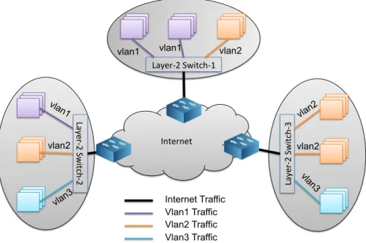
A classical local area network (LAN) topology consists of ethernet switches that connect hosts via different ports. When a host sends a data frame to a switch, once this frame reaches a port, it will be broadcast to every device connected to this switch. This broadcasting feature has the potential to cause the traffic congestion within the LAN. The early solutions were to use routers to split a single LAN into multiple small LANs [107], but the forwarding at a router is not as fast as it is in a switch when the data rate gets faster, so the virtual local area network (VLAN) [37] was introduced, which not only splits a large LAN into small LANs, but also allows multiple end systems belonging to one or more physical LANs to be bridged into a single broadcasting logical LAN with a specific identification (i.e., VLAN tag). Fig. 1 presents a typical example of three VLANs across three physical domains, and these VLANs are differentiated by their VLAN tags (i.e., vlan1, vlan2 and vlan3).
The benefits of VLAN are manifold. First, it enables flexible network manage-ment. VLAN configuration is usually conducted by software, so it is easy to move a host from one VLAN to another VLAN by updating the VLAN identifier (VLAN ID) of the corresponding port that this host connects to. Second, we are able to virtually group de-vices from different physical LANs into a single VLAN, and the data forwarding is done at layer-2, rather going through a router, so that high data-rate traffic exchange can be achieved. Third, by creating multiple VLANs at a single switch, data frames will not be broadcasted to every the ports on the switch. In other words, traffic within different VLANs are partitioned and secure.
Layer-‐2 Switch-‐1 Lay er-‐ 2 S w itc h-‐2 Lay er -‐2 S w itc h-‐ 3 Internet vlan1 vlan1 vlan1 vlan2 vlan2 vlan2 vlan2 vlan3 vla n3 Internet Traffic Vlan1 Traffic Vlan2 Traffic Vlan3 Traffic
Figure 1: An Example of Virtual LANs
Creating VLANs over a network is like partitioning the network horizontally into small logical domains. Although it does not involve either node or link virtualization yet, it partitions the ports on the switches, where a logical domain with entities physi-cally located in various domains is constructed, and traffic is segregated between logical domains.
1.1.2 Virtual Private Network
A virtual private network (VPN) [43, 47, 97] is a logical private network that shares some common resources on the public networking infrastructure, but usually re-quires users to access with credentials. Compared with the public network, a private network, which also refers to enterprise private network, where network entities (e.g.,
Public Internet (Backbone Network) A-‐1 A-‐2 B-‐1 B-‐2 B-‐3 Tunnel for VPN A Tunnel for VPN B A VPN A B VPN B R1 R2 R3 R4 Backbone Link
Figure 2: An Example of Two VPNs over the Public Backbone Network
routers, switches, etc.) usually are actually owned and managed by an business organiza-tion (e.g., company, university, etc.) and only people with authorized permission within the private network can access the resources. Without the VPN, if a business organization is expanded to multiple sites where each site is physically in a different location and forms a private network, although these private networks belong to the same community, users from one site could not access resources in another site, because these sites are intercon-nected by the public network. Thus, the VPN helps to construct a logical private network that tunnels multiple private networks owned by a single administrative domain but geo-graphically in different locations, and the tunnels are end-to-end virtual links constructed over the common underlying public networking infrastructure.
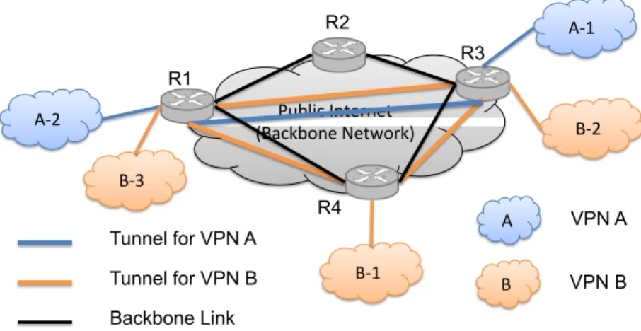
With VPN service, an access point to a private network can be expanded to any-where by creating encrypted tunnels over the public Internet. Fig. 2 shows an example of two VPNs constructed over the public backbone network. In this example, VPN A
crosses two physical sitesA-1andA-2, and a tunnel connecting these two sites is estab-lished between the backbone routers R1, and R3. For VPN B, there are three different physical sites, and the tunnels forVPN Bare amongR1,R3, andR4.
In general, it is the VPN service provider who provides VPN services to customers [43], and the VPN can be implemented at different layers of the TCP/IP protocol stack, along with proper tunneling protocols, the layer-1 VPN was briefly discussed in [43], and the most common types of VPNs are the layer-3 VPN and the layer-2 VPN. For the Layer-3 VPNs (i.e., IP-based VPN), the packets sent from the VPN customer sites are IP packets, and these packets then be wrapped by adding encapsulating headers (e.g., GRE [54], IPsec [64], MPLS [80, 97], PPTP [53], L2TP [108], etc.). As the encapsulated packets arrive at the VPN customer networks, the actual IP packets from the sender will be extracted and sent to the destination. On the other hand, a layer-2 VPN constructs an end-to-end tunnel for delivering encapsulated Ethernet or ATM packets. Since MPLS protocol has the advantage to carry any type of packets, it could be one of the approaches to wrap the layer-2 frames [80, 97].
Although the VPN services also achieve traffic segregation by encapsulating the packets and creating point-to-point tunnels between customer networks, the VPN traffic is still competing with other Internet traffic, so VPN is a domain-level virtualization.
1.1.3 Overlay Networks
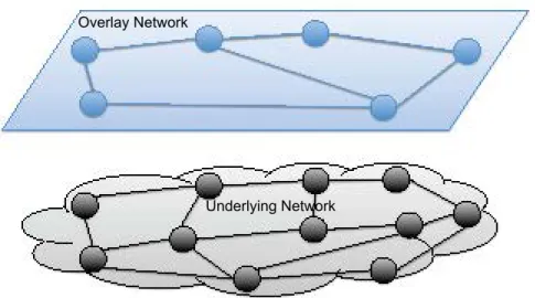
The overlay network [35] is another form of the network virtualization, and it is a logical network over a shared underlying backbone network. The essential entities
Overlay Network
Underlying Network
Figure 3: An Example of Overlay Network
in an overlay network are nodes interconnected by tunneling mechanisms (e.g., GRE tunnels, L2TP tunnels, etc.). The overlay network allows data to be transferred through more secure logic links (e.g., tunnels) over the transport layer or IP layer on the physical network. Fig. 3 shows a typical overlay network architecture, where the overlay topology could be different from the actual underlying physical topology, and the nodes in the overlay network are a subset of nodes from the underlying network.
The overlay network architecture enables data sharing and delivery to be more flexible and resilient, and most of the overlay networks are implemented at the application level. Peer-to-peer network [72,96] was designed for the file sharing purpose, and content delivery network (CDN) [109] allows content data (e.g., multimedia data) to be cached anywhere within the overlay network so that the latency and transport cost can be reduced. Overlay technologies also support a fault-tolerant and resilient network design [14,36,98]. According to the fundamental concept of the overlay, a VPN could be categorized as overlay network as well.
Considering the benefits of the overlay networks, the experimental testbed has been deployed for researchers and students to test and evaluate innovative ideas. The most popular world wide overlay network testbed that has been used for research since 2002 is PlanetLab [34, 87, 88], which consists of more than 1000 nodes (i.e., computers) distributed crossing over 500 sites all over the world. For the first time, Planetlab testbed used the term ”slice” to represent a container for virtual resources (i.e., virtual nodes support by LinuxVserver [38]).
As virtualization technologies evolved, network virtualization has been pushed down to lower levels (i.e., network layer or even data-link layer), and a deeply pro-grammable virtualized networking environment can be well modeled.
1.2 Virtualized Network Environment
A virtual network inherits the generic characteristics of the overlay network, and it potentially provides a partitioned, QoS guaranteed, trustworthy environment for service providers. Thus, the network virtualization [32] is considered one of the promising tech-nologies for Future Internet architectures, and it is also referred as virtualized networking environment (VNE). In a virtualized networking environment, the underlying physical networking infrastructure (i.e., backbone network) is defined assubstrate network(SN), relative to the virtual networks (VNs).
As the basic elements in a VN, virtual nodes can be created in various ways. With the container-based virtualization [30], a substrate node is virtualized at the operation-system (OS) level, where each virtual node runs a replica of the operating environment
that the substrate node runs and it is completely isolated from other virtual nodes. OS-level virtualization has the least overhead in terms of maintenance and resource provi-sioning. The nodes on PlanetLab testbed currently apply the OS-level virtualization (e.g., LXC [55]), where each sliver [88] is an container where applications can be indepen-dently deployed. Although container-based virtualization results less overhead on the implementation, it lacks flexibility in terms of creating heterogenous VNE (e.g., two vir-tual nodes from a common substrate node run different operating systems). Thus, the full virtualization (e.g., KVM [52]) and the paravirtualization (e.g., Xen [17]) techniques are employed, and both are hardware-level virtualization as discussed in [30, 90].
1.2.1 Layers of Network Virtualization
Unlike the traditional overlay network, tenants of VNs have the opportunity to not only deploy applications, but also test and deploy new protocols at a lower layer within their dedicated VNs, such as new routing protocol or even a non-IP based clean-slate networking architecture (e.g., Information-centric networking [13]). Thus, virtualization techniques allow these tenants to have operational privileges on the virtual nodes with di-verse control levels. Chowdhury et al. [32] lists a number of recent network virtualization projects targeting at different layers. In the following sections, we briefly discuss current network virtualization architectures and implementations using a top-down approach.
1.2.1.1 Application Layer
Planetlab [34, 61, 87, 88] is an example for application-layer virtualization archi-tecture, where VNs are isolated from each other over an interconnected high-speed under-lying research network called Global Research and Educational Network(GREN) [16]. Planetlab users can develop applications within the virtual nodes (i.e.,sliver) on physical Planetlab nodes without affecting other users’ experiments. To support distributed ser-vices running on the Planetlab testbed, data planes (i.e. tunnels between virtual nodes) is provided for users to run large scale experiments. However, PlanetLab does not offer control-plane privileges, so it is a challenge for users to take control over the network events, so a lower-layer virtualized network framework is desired.
1.2.1.2 Transport layer
CoreLab [83] inherits the node management framework (i.e. PlanetLab Central management server) from PlanetLab testbed, and it has explored the flexibility of in-stalling guest OSes to VMs on the physical nodes using KVM [52], where each VM can obtain a private IPv4 address and a particular range of port number. In an early implemen-tation of CoreLab, accessingsliversfrom external network used destination NAT (DNAT), and the CoreLab node OS runs as the NAT server to map the incoming packets to a VM with public IP address to the VM’s private IP address. However, the NAT translation re-duces the throughput and it breaks the end-to-end communication. Hence, a port-space isolation approach was proposed [41] to avoid using NAT at the CoreLab nodes.
with its host, and incoming packets only need to specify the host’s public IP address with a specific port number that has been assigned to the VM, and the Open vSwitch [89] redirects the flow to proper VMs.
1.2.1.3 Network Layer
VINI (virtual network infrastructure) [20] supports virtualization at the network layer. By requesting resources, an experimenter is provisioned not only virtual nodes, but also layer-2 virtual links (i.e., Ethernet GRE tunnels), so that a complete virtual topology is presented to the experimenter. Moreover, users can install the Quagga [63] (i.e., a real routing software support multiple routing protocols like OSPF, BGP, etc.) to make their slivers as virtual routers. In this way, users has the capability to evaluate networking performance by injecting failures at the virtual links or the virtual routers.
1.2.1.4 Link Layer
The VNET project [106] used a composite of virtual private network (VPN) and virtual local area network (VLAN) technologies to construct a layer-2 overlay VNE. VMs are connected through the layer-2 tunneling protocol (L2TP). Since VNET implements a layer-2 virtualization, the upper layers (e.g., IP layer) is agnostic, so that there is an opportunity to design and test a non-IP protocol over VNET. VNET also supports flexible VM migration because the network layer configuration does not need to be changed.
1.2.1.5 Optical Layer
Nejabati et al. [84] presents the challenges and possible techniques for optical network virtualization. Similar to a virtualized IP network, a virtualized optical network comprises virtual optical nodes (e.g., optical network switches, etc) interconnected by logical optical links shared on an administrative optical network. The major challenge of implementing virtualization at the optical layer is due to the analogue nature of the optical network resources (e.g., fiber, wavelength, etc.) whose switching granularities are diverse.
Both optical node and optical link virtualization utilize the same concepts: Par-titioning (1:N) and Aggregation (N:1). For virtualizing the optical nodes, partitioning means dividing1OXC/ROADM intoN small units, where each unit is assigned a range of ports from the optical nodes; aggregation is to create a single optical super-node that aggregates N physical nodes and presents one interface to the external world. For vir-tualizing optical links, partitioning refers to creating sub-wavelength channels that carry a portion of data rates of the original wavelength channel. For instance, a wavelength channel of 40Gbps can be divided into two sub-wavelength channels with 30Gbps and 10Gbps, respectively. Aggregation is to create a super-wavelength channel by combining a group of wavelength changes.
1.2.2 Business Role Model and Virtual Network Management
In a VNE, the traditional Internet service provider (ISP) is divided into two busi-ness roles [32]: substrate network provider (SNP) and service provider (SP). Schaffrath
et al. [99] presented a model for the VN management with four different business roles as follows:
• A substrate network provider (SNP) owns the physical network infrastructure con-sisting of physical nodes supporting virtualization and the high-speed backbone connectivity (e.g., fiber connection). The SNP also leases the substrate resources (e.g., computing and bandwidth or circuits) according to the demand from the cus-tomer (e.g., service provider), so that the QoS of the leased VN can be guaranteed.
• A virtual network provider (VNP) communicates with one or more SNPs to orga-nize the virtual resources and fits them into a virtual topology that might be re-quested by the tenant or optimized by the VNP itself.
• A virtual network operator (VNO) mainly takes care of VN initialization such as node installation and configuration. Moreover, the VNO has the permission to run operation on the VN for not only maintenance, but also realizing VN restoration from failure through some reconfiguration mechanism.
• A service provider (SP) is the tenant of the virtual network who rents resources from the SNP and owns an dedicated VN to deliver services to its own customers.
It is possible for a company to fill more than one roles listed above [99]. As pre-sented in Fig. 4, we assume the substrate network owner plays triple-roles of SNP along with VNP and VNO, and the latter two roles are combined into a single logical role called virtual network manager (VNM), which is in charge of VN initialization, maintenance and reconfiguration.
Substrate Network Provider Virtual Network Manager
Virtual Network Provider Virtual Network Operator
Service Provider
Figure 4: Virtual Network Management Business Roles
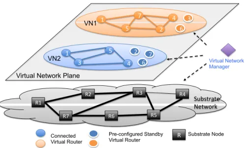
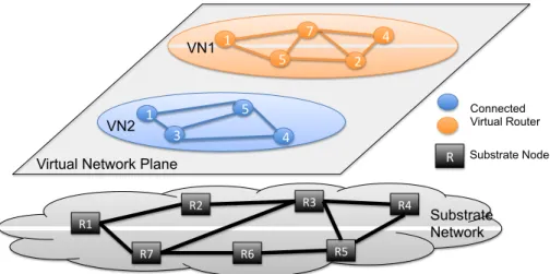
Fig. 5 shows a standard overlay virtualized network environment consisting of a virtual network plane and underlying substrate network. Two VNs are presented in the virtual network plane, and each VN has its own virtual topology consisting of virtual nodes from a different subset of substrate nodes. By renting the resources from the SN, an SP expects the VN to be well maintained and robust to failures. Therefore, an efficient virtual network management mechanism and a resilient virtual network environment is desired.
In the business role model presented in Fig. 4, the VNM conducts flexible VN management through programmable interfaces towards the virtual network plane, and such VN management includes two major tasks: VN initialization and VN reconfigura-tion. VN initialization usually refers to thevirtual network embedding problem [33, 44, 56], and this is one of the main research challenges in the network virtualization. Effi-ciently VN embedding is to achieve optimal mapping between virtual nodes and virtual links and the substrate network, so that the SNP can accommodate as many VN requests as possible. The VN reconfiguration aims to enhance resiliency and survivability of the
R1 R2 R7 R6 R5 R4 R3 Substrate Network R Substrate Node Connected Virtual Router 1 4 5 3 1 4 2 7 5 VN1 VN2 Virtual Network Plane
Figure 5: An Example of Virtual Network Environment
VNE under failures or other evens (e.g., network traffic engineering). Taking the advan-tage of the programmable interfaces towards the virtual network plane, the SNP is able to monitor the VNs, identify the abnormal behaviors or failures, and reconfigure the virtual links (VLinks) or the virtual routers (VRs) to restore the affected VNs.
1.2.3 Virtualized Networking Testbed
Consider the programmability, partition and flexibility of a virtualized networking environment, it is desired to build virtualized networking testbed to support innovative re-search diversity, where rere-searchers are able to request computing resources or networking resources or both to conduct large scale experiments. There have been quite a few virtu-alized networking testbeds deployed globally or locally in a country or continent. Table 1 compares a number of network testbeds that support virtualization.
PlanetLab is a globally distributed networking testbed that supports application-layer virtualization. It uses the OS-based virtualization technique (i.e., LXC), so each
Table 1: Comparison table of Testbed supporting VNE
Testbed Coverage Major Virtualization Virtualization
Resources Technique Layer
Planetlab [11, 88] Global Containers LXC Layer-7
CoreLab [83] Japan VMs KVM, LXC Layer-4
VINI [20] US Containers Trellis Layer-3
GpENI [6, 79] US, Europe Containers Trellis, Linux vServer, VLAN Layer-2,3,&7
Emulab [1, 57] Global PCs and VMs OpenVZ, FreeBSD Jails, Xen Layer-2,3
OFELIA [9, 39] Europe OFS, VCtrler VeRTIGO Layer 2
FITS [2, 82] Brazil VMs, OFS Xen, FlowVisor Layer-2,3
GENI [3, 21] US VMs, OFS OpenVZ, Xen, KVM Layer 2,3
UCLP [12, 49] Canada Lightpaths Partitionting/Aggregation Optical Layer
OF: OpenFlow; OFS: OpenFlow Switch: Ctrler: Controller VMs
sliver is a container that runs the same OS as its host. PlanetLab users are able to test novel application-level services (e.g., P2P, distributed storage system, etc.) within their slices, but they are facing the challenges in creating arbitrary topologies and running experiments for traffic engineering. On the other hand, OS-based virtualization limits the flexibility of customizing the kernel of the OS within theslivers.
As we have mentioned in Section 1.2.1, there are two testbeds were deployed based on the experience of building PlanetLab: VINI [20] in the United States and Core-Lab [83] in Japan, and both are running the private instance of PlanetCore-Lab Central man-agement server called MyPLC [62] to manage the nodes on the testbed. VINI nodes run Trellis [22] that combines two OS-based virtualization techniques (i.e., Linux vServer and NetNS [7]) to allow each virtual network has its own network namespace. Com-pared with PlanetLab, the CoreLab has introduced the full virtualization technique (i.e., KVM) so that users can customize the guest OSes. Du et al. [41] have achieved port-space isolation on the CoreLab nodes using Open vSwitch [89] in their recent work.
network testbed aiming to provide programmability across the entire protocol stack (i.e., application, transport, network, and data-link layer). The GpENI testbed was initially created over the regional optical network between the four universities in the midwest of the United States, which are the University of Kansas (KU), the University of Missouri - Kansas City (UMKC), the University of Nebraska - Lincoln (UNL) and Kansas State University (KSU). Currently, the GpENI testbed spans both the United States and Europe, and it is expanding to Asia. GpENI supports virtualization at three layers. For the appli-cation layer virtualization, it inherits the implementation of PlanetLab platform, where MyPLC is in charge of node management; for the network layer virtualization, it runs a customized instance of VINI software; and for the link layer virtualization, it utilized the VLAN technique.
Emulab [57] is a distributed PC cluster testbed. Both Xen and container-based virtualization (e.g., FreeBSD Jails [95] & OpenVZ [10] ) are utilized to create virtual nodes, and the virtual links are implemented at layer-2 or layer-3. OFELIA [9] is an European OpenFlow (OF) [78] network testbed, and the main resources are OpenFlow switches and VeRTIGO [39] is a FlowVisor [103]-based network virtualization tool to slice the OpenFlow network at layer-2. FITS [2, 82] is a virtual network testbed in Brazil, and it supports virtualization in both IP networks and OpenFlow networks.
GENI [21] is a fast growing distributed large scale testbed providing virtualized networking environment in three aspects. First, computing and storage resources are vir-tualized using all three possible approaches (i.e., container-based, Xen and KVM). Sec-ondly, a variety of tunneling mechanisms (i.e., GRE, EGRE) are available to create virtual
links between VMs, depending on the virtualization techniques used for slicing the nodes. In particular, a tool calledstitcher[85] is available on GENI to create isolated high speed virtual links by establishing VLAN between VMs. Compared with the data-rate limit of GRE/EGRE tunnels (i.e., 100Mbps), stitched links supports gigabits data rates, so ex-periments requiring large data transferring (e.g., video streaming) can be well supported. Thirdly, like OFELIA, GENI also supports virtualization in OpenFlow networks. More-over, GENI testbed is still growing by federating with other testbed, so that GENI users can run larger and more complex experiments using both resources from both GENI and other testbeds.
User-Controlled LightPaths Project (UCLP) [12, 49] allows users to dynamic re-configure optical networks, with the partitioning or aggregation scheme to divide or com-bine lightpaths.
1.3 Failure Types and Fault-Tolerance Schemes
Cetinkaya et al. [25] presented a taxonomy of challenges in the networks, and summarized events that may have impact to the network operations or cause failures in the network. Markopoulou et al. [75] collected the data regarding the failures on the Sprint backbone network and classified the failures into two top-level categories: maintenance (20%) and unplanned failures (80%). Among the unplanned failures, about 70% were identified as single-link failures, whereas 17% and 12% were identified as router-related failures and optical-related failures, respectively. In particular, the authors claims that the router-related failures may due to a router crash, a linecard failure, overload CPU, etc
[74]. For optical-related failures, since IP network can be considered an overlay network on the optical network, so an optical link failure could affect multiple overlay IP links concurrently.
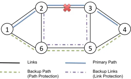
Protection (proactive) and restoration (reactive) are the main fault-tolerant schemes for survivability in both optical networks [93] and IP networks [75]. In general, a pro-tection method refers that the primary network entities are provided alternative network elements (i.e., paths, nodes, etc) in case of failures. For example (see Fig. 6), two paths (a:1-2-3-4 andb:1-6-5-4) are precomputed between node-1 and node-4, and let pathbbe reserved as protection path. If the link 2-3 fails, it affects the primary patha, and the traffic forwarding between node-1 and node-4 will be protected by the backup pathb. Fig. 6 also showed a link protection in case of link 2-3 fails, where links 2-6, 6-5 and 3-5 are reserved for protecting the link 2-3. With the protection scheme, two types of backup have been widely discussed: dedicated and shared backup, respectively. For the dedicated backup, it is a one-to-one relation, where a critical entity the network has been assigned a backup entity for protection purpose. For the shared backup, the resources reserved for backup purpose can be used to protect more than one failure. For the restoration, the backup resources can be dynamically discovered in an on-demand manner. In other words, when a failure occurs, the restoration scheme will dynamically find a backup path or node to restore the network.
In a VNE, a fault-tolerant scheme should be able to provide protection against failures in either VNs or the underlying SN. There have been many works done toward
1
2
6
3
5
4
Links Primary Path
Backup Path (Path Protection)
Backup Links (Link Protection)
Figure 6: Path/Link Protection Scheme
survivable virtual network embedding problem that considers to allocate redundant re-sources while mapping VNs to the SN [56], and most of them focused on the link failure recovery. However, a node failure is more common and it has more impact in a VNE than it is in the physical network. First, a virtual node may fail due to the failure in the corresponding functional software. For example, a crash in a routing software can fail a virtual router. Second, although a physical node failure is less common than a physi-cal link failure, it may affect multiple VNs that contain virtual nodes provisioned by this failed physical node on the SN, and the the failed virtual nodes will in turn cause multiple virtual link failures in these VNs. Therefore, it is important to design an efficient VN restoration scheme for the node failures in the VNE.
1.4 Problem Definition
The primary goal of this dissertation is to design an optimal standby virtual router (S-VR) selection model that can be adapted into a dynamic reconfiguration scheme for a
software-defined resilient virtual network environment, so that virtual networks with node failures can be quickly restored with properly selected standby virtual routers.
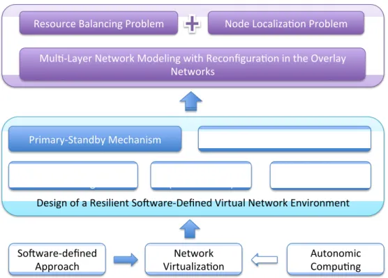
Fig. 7 presents a system view of the overall problem definition. To design a software-defined resilient VNE, we consider three pieces of techniques: network virtu-alization, software-defined approach and autonomic computing [65]. For the network virtualization, we make several underlying assumptions: (1) the VNE implements the layer-3 virtualization, each virtual node in a VN is configured as a virtual router (VR) running a particular routing protocol; (2) At the VN embedding phase, an SNP is able to not only provision the basic resources based on the VN tenants’ requests, but also provide additional VRs as standby virtual routers (S-VRs) for this VN to improve the resiliency; (3) We consider recovery from a failure that occurs at core VRs, not edge VRs of the VNs. A key feature of software-defined networking (SDN) [77] is that the control-plane functionalities are decoupled from the data-plane and they are abstracted into a central-ized control system. Thus, we incorporate this idea into virtual network management, where a centralized virtual network manager (VNM) performing as both roles of VNP and VNO. From the fault-tolerance perspective, the VNM implements the dynamic re-configuration function to automatically restore VNs from node failures using S-VRs. The concept of autonomic computing is applied into the dynamic reconfiguration process to achieve self-healing in the VNE, so that node failures are transparent to the SPs.
We consider a primary-backup mechanism for the fault-tolerance in terms of node failures recovery in the VN. Specifically, each VN is provisioned an extra group of VRs as standby virtual routers (S-VRs) and each S-VR can be used to replace any failed VR
Network
Virtualiza/on Autonomic Compu/ng So8ware-‐defined
Approach
Design of a Resilient So8ware-‐Defined Virtual Network Environment
Centralized Virtual
Network Management Fault-‐Tolerance (Node Failure) & Fast Restora/on Self Configura/on
Primary-‐Standby Mechanism Op/mal Mul/-‐Criteria Selec/on
Mul/-‐Layer Network Modeling with Reconfigura/on in the Overlay Networks
Node Localiza/on Problem Resource Balancing Problem
Figure 7: A System View of the Problem Definition
in the existing VN. Our goal is to design an model to optimally pick an S-VR for the VN restoration under multiple selecting criteria, and this model can be applied into an overlay networking environment. More specifically, the proposed model addresses two major problems, which are the resource balance (i.e., load balance on the substrate network) and the node localization problem (i.e., which S-VR should be selected).
Therefore, in this dissertation, we address the problem of selecting optimal S-VRs when VRs in the core virtual networks are affected due to a failure. End hosts may be connected to multiple edge nodes, and the loss to end users is not the focus of this work. The scope is to recover from a failure that occurs at core VRs,notedge VRs of the VNs.
1.5 Contribution of the Dissertation
In this section, we briefly summarize the major contribution of this dissertation. 1.5.1 Dynamic Reconfiguration Scheme for Node Failures in a VNE
Primary-backup mechanism is commonly used for resilient network design. For example, for link failures, backup paths can be pre-computed to by detouring the traffic, and for node failures, backup routers might be available to be quickly activated. In our work, we consider to restore the VNs suffering a VR failure with astandby virtual router (S-VR).
Unlike the dedicated primary-backup approach, for a set of S-VRs provided for a VN, any of the S-VRs can be used to replace any failed VR in this VN. In other words, these S-VRs are identical, in terms of configuration. In order to efficiently restore the VNs with VR failures, a dynamic reconfiguration scheme is applied for this situation.
1.5.2 An Experimental Study on GpENI-VINI [67]
Before exploring the optimization model, we first designed an dynamic reconfigu-ration system for the virtual network manager (VNM) to achieve dynamic reconfigureconfigu-ration in a VN and deploy the DRS on the GpENI-VINI testbed. This is a joint work with Parik-shit Juluri, who is also a PhD student in the Network Research Lab (NeTReL) at the University of Missouri - Kansas City.
S-VR based on the geographical distance between an S-VR and the failed VR (2) dynam-ically replacing the failed VR with the selected S-VR in the existing virtual topology, so that the affected VN can be restored without involving manual operations. Our goal spans to four aspects: (1) Conduct an experimental study on a wide-area virtualized networking testbed to evaluate the dynamic reconfiguration scheme; (2) Understand the DRS’s im-pact to the network dynamics because the realistic packet loss or bandwidth availability are part of the environment. (3) Evaluate the impact on the routing convergence time un-der existing routing protocol (i.e., OSPF) during the reconfiguration; (4) Test autonomic management in a realistic VNE and learn the challenges of applying the dynamic recon-figuration system in such an environment.
The experimental study of deploying the dynamic reconfiguration scheme in a realistic virtualized networking testbed showed us a couple of lessons. First, dynamically restoring a VN from a VR failure is practical in a real VNE and the restoration process was fast, but the DRS cannot control the inherent properties of the network (e.g., routing table convergence time). In addition to the geographical distance, more criteria should be considered when making the selection. Second, multiple independent runs are important for implementing an experimental study on a realistic network testbed.
1.5.3 Design of a Multi-Criteria Standby Virtual Router Selection Model [68] Based on the lessons and the experience from the experimental study, we designed an MILP model for a multi-criteria S-VR selection that can be applied into the dynamic reconfiguration scheme for any node failure in a VNE.
We first modeled the basic entities (e.g., nodes, links, topology, VNs, interfaces, etc.) within a VNE along with a number of constraints to the selection. We then defined cost functions associated with the selection process, where each cost function is repre-sented as an aggregated weighted factors. Moreover, the final goal is to minimize both of the network cost and the maximum bandwidth utilization on the substrate nodes. Accord-ing to the optimization model, we designed a heuristic algorithm as well. The proposed model is able to find optimal S-VRs to restore multiple VNs suffering from concurrent VR failures, where the VR failures could be caused by either a software failure at itself or a substrate node failure.
To evaluate the results, we first study the weight parameters defined in the cost functions and the objective function, and find out how to set the weights to each factors under a certain circumstance. Second, we designed experimental scenarios to study the impact of a variety of factors to the S-VR selection, these factors are dependent on the network dynamics and the resources provisioning. The results showed that the proposed heuristic’s performance was close to the optimization model when there were sufficient standby virtual routers for each virtual network and the substrate nodes have the capability to support multiple standby virtual routers to be in service, concurrently.
1.5.4 Design of a Software-Defined Resilient VNE on GENI [66]
For this phase, by collaborating with Sarah Edwards and Niky Riga from GENI Project Office at Raytheon BBN Technologies, we designed a software-defined resilient
VNE on the GENI testbed. As we introduced in Section 1.2.3, GENI provides a large-scale distributed heterogenous VNE, and we are able to create a layer-3 virtual networks by creating tunnels and virtual routers.
Fig. 5 shows a logical view of the a VNE with a centralized VNM that implements the dynamic reconfiguration scheme. Based on this abstraction, we designed functional modules for the VNM, so that network initialization and reconfiguration can be automated on the GENI networks. In particular, we developed a tool to automate arbitrary VN initial-ization on the GENI testbed, and customized this tool to create VNs with a set of S-VRs. For the S-VR selection, we simplified the objective function from the optimization model, and only considered a weighted impact of the geographical distance and the VM load on the GENI nodes, and we present a prototype implementation of the VNE using GENI as the substrate network.
1.6 Additional Collaboration and Projects
I have been a collaborator on a number of projects during my PhD studies at University of Missouri - Kansas City, and they resulted in the following publications [15, 29, 42, 69, 70, 79, 94, 110, 111], and these contributions are described briefly in the following subsections.
1.6.1 GpENI Project
As one of the collaborators in the GpENI project, our (i.e., UMKC team) primary goal was to establish a layer-3 virtualization infrastructure testbed to support programma-bility at the network layer on the GpENI testbed. Consider the VINI project has built
a programmable network-layer virtualization testbed, and there is a private VINI central management server called MyVINI) available for us to create an instance of VINI envi-ronment, we created a server running MyVINI at UMKC. Thus, the private VINI environ-ment built on the GpENI network is named GpENI-VINI, and MyVINI server manages the GpENI-VINI nodes distributed at different GpENI sites in the US and Europe.
We have made several customizations from the ordinary MyVINI environment to support a more flexible resource provisioning and management as described in [29]. First, we successfully deployed XORP v1.7on GpENI-VINI slivers. Second, we ex-tended the features of the original IIAS tool deployed for the public VINI testbed, so that the GpENI-VINI server allows users to create arbitrary virtual topologies with less restrictions on manipulating virtual links. Third, we developed a tool to automated the routing software installation process, and it allows users to efficiently install XORP or Quaggato allsliversin aslicesimultaneously.
By successfully deploying these three features into the standard VINI software, we had insightful understanding about the underlying architecture of the Trellis software that runs as a core software for VINI nodes. The experience of implementing XORP within asliverreveals that the mapping between virtual interfaces and physical interfaces shall be considered when creating the XORP configuration files of routing protocols, and this shows one of the differences between running a software router in a virtual node and a physical node. On the other hand, automating the routing software installation process for allsliverslargely improves the efficiency of setting up an virtual IP network with active virtual routers.
0 1 2 3 4 5 6 7 8 9 10 60 80 100 120 140 160 180 200 220 240 260
Time of Generating Xorp Configuration Time
Number of Virtual Interfaces
Microseconds
router−1.umkc router−2.ethz router−1.ksu
Figure 8: Time to Generate the XORP Configuration File within a Single Slice [79]
In this project, we also studied how the virtual router configuration would be affected by the substrate GpENI-VINI nodes. Since GpENI-VINI testbed uses Linux-vServer to create virtual nodes, the mechanisms of both CPU scheduling and I/O QoS use fair share and reservation [105], so users have no control on reserving resources by giving specific requests. Hence, the performance of the sliverdepends on the hardware configuration of its substrate host. Fig. 8 presents the time to generate the defaultXORP configuration files at three differentsliverswithin a single slice, respectively. We found the distinction between the time of generating the routing configuration files insliverson different physical system. On the other hand, from a single host’s perspective, hosting multiple containers does not have significant impact to the performance (see Fig. 9)
0 2 4 6 8 10 12 14 16 18 20 22 100 150 200 250 300 350 400
Number of Virtual Interfaces on Router−1.KSU
Microseconds
Time of Generating Xorp Configuration File at Router−1.KSU 1 sliver
3 slivers 5 slivers 11 slivers
Figure 9: Time to Generate the XORP Configuration Files for Multiple Slices [79]
1.6.2 SeRViTR Project
The Secure and Resilient Virtual Trust Routing (SeRViTR) project has been re-sulted in a number of publications [15,70,110,111]. It was a joined collaboration between Osaka City University (OCU) in Japan, Arizona State University (ASU) and University of Missouri - Kansas City (UMKC) in the United States. The goal was to design a trustwor-thy and resilient network architecture supporting multiple virtual routing domains, and we built a testbed prototype implemented between the three universities.
Virtualized networking environment allows service providers to obtain a parti-tioned and QoS guaranteed virtual network. In this project, in addition to constructing virtual routing/switching domain, we further explored a fine-grained VNE design that enables user-centric virtual routing domain to be created for services with different trust-worthiness. In [70], we presented a comprehensive SeRViTR framework design to realize
a virtual trust routing and provisioning domain (VTRouPD) and a µVTRouPD, where the latter one indicates a sub-domain comprising virtual routers/switches within a single VTRouPD or spanning multiple VTRouPDs, determined by a particular routing policy. For the SeRViTR framework, we designed the core components that are responsible for trust management, creating virtual routing domains and controlling flows, respectively. We validated our design using an OpenFlow-based implementation, and the virtual rout-ing domain was distrout-inguished by variousVLAN IDs. In our validation testing, we consid-ered two types of applications: SSH and HTTP, where the SSH flow was assigned a higher trust level, and the correspondingµVTRouPD for the SSH flow was created; whereas the HTTP flow was sent within aµVTRouPD with a lower trust level. Later on, we proposed a behavior-based policy management for SeVRiTR framework [110], where the trust level can be updated based on the judgement on the behavior of the flow registered at the rel-evant database. Furthermore, the impact to the trust level within a single VTRouPD may also affect the trust level negotiation between multiple VTRouPDs. Thus, this add-on fea-ture to the SeRViTR framework potentially enables a trust level reconfiguration for virtual routing domains.
The second goal of this project was to build a geographical distributed SeRViTR testbed consisting of multiple VTRouPDs, where each VTRouPD belongs to an admin-istrative domain. In [111], we presented aGeo-Distributed Programmable Layer-2 Net-working Environment (G-PLaNE)as a substrate support for the SeRViTR testbed, which provides networking, computing and storage capabilities. For the computing resources, we use Xen to provision VMs for basic functional components (e.g., Policy Manager,
VTRouPD Manager, etc) of the SeRViTR framework presented in [70]. For network re-sources, we used OpenFlow switches asFlow Controllersthat redirect flows to different µVTRouPDs based on the trust level assigned by thePolicy Manager. To interconnect the VTRouPDs constructed in the three universities (i.e., OCU, ASU and UMKC) from the US and Japan, we create a layer-2 GRE tunnel between any two universities using OpenFlow Switches. Thus,VLANis supported over this layer-2 GRE tunnel.
1.6.3 Systematic Experimental Design on a Shared Testbed
By collaborating with the GENI Project Office and based on our experience on using GENI testbed, we contributed a case study in [42]. In the presented case study, we showed how to conduct experiments systematically on a publicly shared testbed. Table 1 shows that most testbeds today offer resources shared by all experimenters and they pro-vide realistic networking environment for evaluating novel applications or protocols. To efficiently use the resources on the testbed and avoid unnecessary time-consuming debug-ging, we present two golden rules for systematic experimental design: (1) always starting with the smallest setup for an experiment (2) always making one change at a time when scaling up the experiment.
Another lesson we learned by running the experiments for the study case is that it is important to always save the configuration for our experiments (e.g., RSpec [21] for GENI testbed) before making any changes to the current experimental setup. This procedure also helps us to quickly recreate the identical experiments on the testbed due to various reasons. For example, if there is a planned long-term maintenance at a GENI
site where we have reserved resources from, it will impact a few virtual links and nodes in our topology for a while. To bring up the same experimental environment, we can create another slice and load the same RSpec we have saved and replace the nodes under maintenance with the ones from other active sites.
1.6.4 Service-Centric Management in Information Centric Networking
The work presented in [94] was in collaboration with Ravindran et at. from Fu-turewei R&D Center. In this work, we designed a push-based multi-tier management framework for edge cloud service over theinformation centric network (ICN)[112]. ICN is another popular field in the Future Internet research, and it proposes to design a clean-slate networking architecture, where the identifier and locator of the information are de-coupled and the information can be cached anywhere within the network. Relying the name-based routing proposed for the ICN architecture, we designed an overlay service access layer crossing from edge network to the core network, and simulated a conference framework as an ICN-based edge-cloud service.
1.6.5 Understand the benefit of Multipath Routing
Our recent work on [69] studied the benefit of multi-path routing by introducing amultipath measure (MPM). We first presented a theoretical MPM for each of the three common traffic engineering objectives and then ran the linear programming to compute the optimal MPM for topologies in diverse types and sizes. Consider a multi-commodity scenario, for all node-pair demands under a certain traffic matrix, the numerical results showed that the exact MPM value obtained from the ILP was zero or close to zero at
optimality. By comparing the objective value with the single-path routing, the multi-path routing showed little gain, especially for the topology comprising more than 25 nodes.
1.7 Outline of the Dissertation
In this dissertation, we address the problem of dynamically selecting optimal standby virtual routers for one or more virtual networks against node failures in a vir-tualized networking environment, with consideration of various constrains and costs in the virtual networks. In Chapter 2, we present a literature survey about the fault-tolerance scheme used in survivable network design and recent works in autonomic network man-agement and centralized network manman-agement, respectively. We then illustrate the design of a dynamic reconfiguration scheme in a VNE in Chapter 3. In Chapter 4 we present the experimental study of deploying the dynamic S-VR selection in regard of a VR failure on the GpENI-VINI testbed. Chapter 5 presents the optimal S-VR selection model and relavent numerical results. Chapter 6 presents the prototype design and implementation on GENI testbed. Finally, we summarize our work and briefly discuss the future research goals in Chapter 7.
CHAPTER 2 LITERATURE SURVEY
A recent survey [44] classified the virtual network embedding approaches into three categories: concise/redundant, static/dynamic, centralize/distributed, where each category has two options. Our work considers one of the eight combinations of these six features, that is, {redundant, dynamic and centralized}. A virtual network embedding with redundant resource provisioning is also referred as survivable virtual network em-bedding [56]. Moreover, the centralized and dynamic approaches refer the management mechanisms that can be used in either the embedding or the reconfiguration procedure.
As discussed in Chapter 1, a VNE is presented as an overlay architecture, and it is conceptually similar to the traditional IP-over-optical network architecture, where the underlying network is the optical ring/mesh topology and the IP-layer links shares the fiber links. Thus, the traditional survivable design for the optical-layer could be still extendable for designing a survivable VNE. For example, the survivable virtual network embedding aims to provide spare resources to protect link/node failures in a VNE, and this approach inherits the protection scheme used in the survivable optical network design.
In this chapter, we first present a literature survey on survivable design for optical networks and virtual network embedding, and then we briefly discuss about dynamic virtual network reconfiguration and centralized management that are also popular research areas for virtual network management.
2.1 Survivable Optical Networks
In the optical networks, link failures are more common than the node failures. Sivakumar et al. [104] presents a survey on the survivability optical networks in two common topologies: the SONET/SDH ring topology and the WDM mesh topology.
For the SONET/SDH ring topology, there are three standard protection schemes [104]: (1) autonomic protection switching (APS) (2) dual homing (3) self-healing rings. The APS is used to provide link protection in either dedicated or shared backup manner. Dual-homing mainly handles the single-node failure in the ring topology, where a backup node is provided for a critical node (e.g., a major hub in the network). The self-healing ring is used to protect both link and node failures.
In a WDM mesh networks, connection between two nodes are called lightpath, and a lightpath usually spans a series of fiber links, or a fiber link may be shared by multiple lightpaths. Thus, a failure at a fiber link may affect multiple lightpaths that share the failed link in the optical network. Most of the works [40,73,93,118] addressed the link failures in the WDM mesh network by considering the protection or restoration scheme, and the specific survivability designs for link failures are at the path-level or the link-level. For the protection scheme, backup resources are preplanned before the failure occurs. In the dedicated-backup paradigm, the common ways are 1+1 and 1:1 [104, 118]. In the shared-backup paradigm, the backup wavelength could be shared by multiple paths that do not fail simultaneously, and the paths can be either the primary paths or the backup paths. For the restoration scheme, the backup paths to restore a link or an end-to-end path are computed dynamically after the failures. Although the restoration scheme may not
guarantee that backup resources can always be determined after the failure, it efficiently saves the spare resources. Doshi et al. [40] proposed a1+1 protection against a single-failure scenario, where the backup path between a source and destination is preplanned with links and nodes that are disjoined with the primary path. Chan et al. [26] proposed a self-protected architecture using 1:1 protection in the WDM networks. Mohan et al. [81] proposed a hybrid method that combines the shared-backup protection and a restoration, where a primary path shares a channel with multiple backup paths.
Proactive or reactive mechanisms for node failures in a WDM network are more complex and challenge. Usually a node failure may cause multiple failures in the links that are attached to this node, and to recover these links requires multiple node disjoint backup paths to reroute the traffic traversing these links [104]. Liu et al. [71] proposed a spare capacity allocation model with successive survivable routing for node failures in a mesh topology, where each traffic flow was preplanned a node-level disjoint path so any single node failure along the path can be protected.
2.2 Survivable Virtual Network Embedding
Virtual network embedding problems have been wildly studied in the past decades, and most of them were published in the past five years. The primary goal of virtual net-work embedding is to accommodate each virtual netnet-work request to the substrate netnet-work, where a virtual node usually is mapped to a substrate node and a virtual link is mapped to a substrate paths (i.e., a set of substrate links). Fischer et al. [44] presents a detailed taxonomy of the virtual network embedding approaches, where about 50% of the works
used the redundant approach. Thus, survivability has become an significant element for creating a resilient virtualized networking environment.
As listed in the survey [44], out of the 40 papers that considered redundancy for the virtual network embedding, 34 (about 85%) used a centralized and static approach. A centralized approach is still the most common for virtual network embedding, and the main advantage is that it has the global view of the whole VNE. With static allocation, the resources are preplanned for a virtual network request and cannot be reallocated for an-other virtual network request that comes later, and it lacks flexibility to adapt the changes in the VNE, such as the resource distribution on the substrate network. According to the survey, there have been only five papers combines both dynamic and redundancy in the embedding paradigms.
Survivable virtual network embedding against link failures was addressed in many works [31, 33, 51, 76, 91, 92, 101, 102, 115–117]. In particular, Shamsi et al. [101, 102] present QoS-aware resource allocation from the application’s perspective. The overlay links requiring high quality were mapped to the direct paths on the substrate networks, and alternative paths were provisioned by indirect paths going through intermediate nodes on the substrate network. Zhang et al. [116, 117] also considered a QoS-based allocation, where disjoint backup paths on the substrate network were provisioned against link fail-ures and the latency for the requested virtual network was minimized. While allocating the backup paths, the proposed model aimed to minimize the number of the substrate nodes that were selected to support backup paths. Allocating virtual links that share multi-path splited on the substrate network is another way to improve the survivability against link
![Figure 8: Time to Generate the XORP Configuration File within a Single Slice [79]](https://thumb-us.123doks.com/thumbv2/123dok_us/1985109.2794818/45.918.218.692.187.500/figure-time-generate-xorp-configuration-file-single-slice.webp)
![Figure 9: Time to Generate the XORP Configuration Files for Multiple Slices [79]](https://thumb-us.123doks.com/thumbv2/123dok_us/1985109.2794818/46.918.219.692.185.500/figure-time-generate-xorp-configuration-files-multiple-slices.webp)