Hannes
Hannes
Schwarz
Schwarz
J
J
ü
ü
rgen
rgen
Ebert
Ebert
Andreas Winter
Andreas Winter
Nr. 4/2009
Nr. 4/2009
Arbeitsberichte aus dem
Arbeitsberichte aus dem
Fachbereich Informatik
Fachbereich Informatik
Rechte vorbehalten, insbesondere die der Übersetzung, des Nachdruckes, des Vortrags, der Entnahme von Abbildungen und Tabellen – auch bei nur
auszugsweiser Verwertung.
The “Arbeitsberichte aus dem Fachbereich Informatik“ comprise preliminary results which will usually be revised for subsequent publication. Critical comments are appreciated by the authors. All rights reserved. No part of this report may be reproduced by any means or translated.
Arbeitsberichte des Fachbereichs Informatik ISSN (Print): 1864-0346
ISSN (Online): 1864-0850 Herausgeber / Edited by:
Der Dekan: Prof. Dr. Zöbel
Die Professoren des Fachbereichs:
Prof. Dr. Bátori, Prof. Dr. Beckert, Prof. Dr. Burkhardt, Prof. Dr. Diller, Prof. Dr. Ebert, Prof. Dr. Furbach, Prof. Dr. Grimm, Prof. Dr. Hampe, Prof. Dr. Harbusch,
Jun.-Prof. Dr. Hass, Prof. Dr. Krause, Prof. Dr. Lämmel, Prof. Dr. Lautenbach, Prof. Dr. Müller, Prof. Dr. Oppermann, Prof. Dr. Paulus, Prof. Dr. Priese, Prof. Dr.
Rosendahl, Prof. Dr. Schubert, Prof. Dr. Staab, Prof. Dr. Steigner, Prof. Dr. Troitzsch, Prof. Dr. von Kortzfleisch, Prof. Dr. Walsh, Prof. Dr. Wimmer, Prof. Dr. Zöbel
Kontaktdaten der Verfasser
Hannes Schwarz, Jürgen Ebert, Andreas Winter Institut für Informatik
Fachbereich Institut für Softwaretechnik Universität Koblenz-Landau
Graph-based Traceability – A Comprehensive
Approach
Hannes Schwarz, J¨urgen Ebert, Andreas Winter Institute for Software Technology
University of Koblenz-Landau Koblenz, Germany
February 17, 2009
In recent years, traceability has been more and more universally accepted as be-ing a key factor for the success of software development projects. However, the multitude of different, not well-integrated taxonomies, approaches and technologies impedes the application of traceability techniques in practice. This paper presents a comprehensive view on traceability, pertaining to the whole software development process. Based on graph technology, it derives a seamless approach which combines all activities related to traceability information, namely definition, recording, identi-fication, maintenance, retrieval, and utilization in one single conceptual framework. The presented approach is validated in the context of the ReDSeeDS-project aiming at requirements-based software reuse.
1 Introduction
In the course of software development many different artifacts are produced, ranging from col-lections of requirement statements over architecture and design models to source code and test cases. All these artifacts are strongly coupled. They may build on each other, or their individual elements may contain references to other elements in other software artifacts. This fact leads to a high degree of interdependence. Thus, changing one element in one artifact may lead to the need of changing others, possibly leading to an avalanche of inferred changes.
In order to keep all relevant documents in a consistent, but still interconnected state, their in-terdependencies have to be managed appropriately to support tracing the impact of change for concrete software elements. The common recognition of this necessity has led to the notion of
Besides impact analysis, closely related to software maintenance, other areas of application for traceability have emerged, including program comprehension, project management, quality assurance, and reuse of software artifacts.
The need for an appropriate treatment of traceability information has even increased with the advent of model-driven development methods. Focusing on models and model transformations leads to even more explicit knowledge on the traceability connections between different software elements.
This paper promotes acomprehensive viewon traceability, taking into account the whole soft-ware development and maintenance process. The approach is comprehensive in two senses. First, it incorporates all traceability-related activities ranging from the definition of a metamodel for traceability information to the retrieval and maintenance of traceability information. Second, the approach is not limited to a specific kind of artifacts, for example requirements or source code, but is supposed to encompass all artifacts created or used in the course of software devel-opment projects.
The approach presented in this paper features aseamless combination of all activities related with traceability information in one single conceptual framework with an accompanying im-plementation. All relevant traceability-related activities (defining, recording, identifying, main-taining, retrieving, and utilizing traceability information) are supported by a common
graph-based implementation technologyleading to a smooth integration of these activities to a
com-plete methodological approach. By using graph technology, the various challenges posed by traceability can be tackled on a joint technological foundation. This foundation is simultane-ously precise and efficient and allows for the application of a great body of knowledge on graph algorithms and graph analysis. The applied technology is based on the TGraphapproach to graph-based modeling [Ebe08b].
The approach described here, has been applied in theReDSeeDS1project aiming at the develop-ment of aRequirements Driven Software Development System[ ´Smi06]. More precisely, the goal of ReDSeeDS is to foster the reuse of software engineering artifacts by comparing the require-ments specification of a software system to be developed to the requirerequire-ments specifications of already accomplished development projects. Then, based on identified similar requirements, it is feasible to follow traceability relationships to find other artifacts realizing these requirements, possibly being candidates for reuse in the current project. Furthermore, ReDSeeDS features a model-driven approach for transforming requirements specifications to architecture and detailed design models and further on to source code fragments. The overall approach is validated in an industrial context on the basis of real-life projects.
The paper starts with a general discussion of the term traceability, its related activities in section 2, including a short survey of related work. Section 3 introduces the TGraph approach. The fol-lowing sections discuss the relevant activities against the background of applying the introduced graph technology: section 4 deals with definition and recording of traceability information, sec-tion 5 describes the identificasec-tion and maintenance of this informasec-tion, and secsec-tion 6 presents
retrieval and utilization. These sections are augmented by showing concrete applications of the described technologies in the context of ReDSeeDS. Section 7 concludes the paper.
2 Traceability
Looking at the existing body of literature, it becomes obvious that the origins of traceability as a field of research lie in requirements management [Aiz06]. Many authors dealing with traceability leaned towards putting a system’s requirements specification into the center of re-search activities, resulting in the termrequirements traceabilityto have been used extensively [Got94, Ram01, Wil75]. In recent years, the research community started to devote more effort to exploring traceability of other artifacts of a software development project, such as source code, design, and documentation [Ant02, Mur95, Wit07]. In [Aiz06, Asu07, Str02], traceability is understood as a comprehensive concept encompassing the whole development process, with-out putting special emphasis on the requirements specification. Referring to this interpretation, Spanoudakis and Zisman coin the termsoftware traceability[Spa05].
The following section 2.1 introduces the notion of traceability by discussing various definitions. Then, in section 2.2, different traceability-related activities are described, each one covering different aspects of this field of research. Categorized according to these activities, a short survey of related work is given. Finally, section 2.3 formulates thetraceability challengeaddressed by the approach presented in this paper.
2.1 Definitions of Traceability
The probably most cited definition of traceability to be found in literature has its origins in a work of Gotel and Finkelstein [Got94]:
“Requirements traceability refers to the ability to describe and follow the life of a requirement, in both a forwards and backwards direction [...]”
It can easily be noticed that this definition focuses on requirements traceability, severely limiting its usefulness for the comprehensive traceability approach which is promoted in this paper. A more general definition can be found in the IEEE’sStandard Glossary of Software Engineering
Terminology[IEE90]:
“The degree to which a relationship can be established between two or more prod-ucts of the development process [...]”
Spanoudakis and Zisman offer another definition considering traceability in the scope of the whole development process, additionally including stakeholders and demanding for rationales [Spa05]:
“[Software traceability] is the ability to relate artefacts created during the develop-ment of a software system to describe the system from different perspectives and
levels of abstraction with each other, the stakeholders that have contributed to the creation of the artefacts, and the rationale that explains the form of the artefacts.”
Both of these definitions are sufficient to cover traceability in the varieties and forms treated in the following, consequently dispensing the need to formulate an own definition. However, in order to avoid the more coarse-granular connotation ofartifact, the more general term (traced)
entityshall be used in the following.
An important categorization of traceability used in this paper is the distinction between
intra-levelandinter-level traceability [Kur07], referring to theabstraction levels of traced entities.
“Usual” abstraction levels are, for instance, a software system’s requirements specification, its architecture, detailed design, and its source code. While intra-level traceability applies to trace-ability relationships between entities on the same abstraction level, inter-level tracetrace-ability refers to the relationships between entities on different levels.
To a certain degree, the distinction of abstraction levels depends on the specific case or even the observer. For example, a requirements specification could be split into a set of abstract user requirements and more specific system requirements.
2.2 Traceability-related Activities
In order to structure the field of research, different aspects of traceability can be classified into
sixactivities, taken and adapted from [Pin96, Kne02]: defining, recording, identifying,
main-taining,retrieving, andutilizingtraceability information, i.e. traceability relationships together with traced entities. In the following, these activities are discussed in more detail, including related work.
Definition of traceability information refers to the determination of entities to be traced and traceability relationships between them which are of interest for a specific application. Existing literature on this activity can be roughly categorized into two groups.
Publications falling into the first one are concerned with the design ofreference metamodels
providing a set of entity and interconnecting relationship types [Let02, Poh96, Ram01]. How-ever, it has to be noted that these metamodels focus on requirements traceability, thus neglecting traceability of other entities such as architecture components or source code fragments. Other approaches include tracing variability in requirements and architecture in the context of product line engineering [Moo07] and the usage of ontologies for traceability between source code and documentation [Wit07].
In [Esp06], a so-called traceability meta-type specifies required or recommended elements a concrete traceability relationship type should possess. This generic concept allows for the defi-nition of customized, application-specific relationship types.
The second group of publications related to the definition activity deals with the types, forms, or meaning of traceability relationships. While the previously cited metamodel- or ontology-based approaches distinguish between different types of relationships, the meaning of these types is
informally given, either by a description innatural languageor only implied by the type’s name. An exception is [Poh96], where traceability relationships are augmented by integrity constraints. A similar approach is pursued in [Dri08].
A further step towards formalization is taken in [Car01, Dic02], where relationship types be-tween requirements are mapped to logical and mathematical expressions. So-calledcost/value
interdependenciesare employed in [Dah03] to denote positive or negative effects of the
imple-mentation of some requirement on the cost or value of another requirement’s impleimple-mentation. In [Aiz05], relationship semantics are formalized byevent-condition-actionrules. The specifi-cation of relationship semantics bylogic formulaeis proposed in [Gok08].
A shortcoming of many traceability approaches is that they treat traceability relationships as
binary links, i.e. as a connection between two entities only. By allowing forn-ary relationships,
UML [Obj07] and the approach pursued in [Mal05] are two of the few exceptions here.
Recording is concerned with physically holding traceability relationships in the form of data structures. There exist two basic variants: On the one hand, relationships can be recordedwithin
traced entities by introducing textual references [Son98, Wie95] or hyperlinks [Kai93]. On
the other hand, numerous concepts for holding traceability information externally have been developed, based on different technologies.
The most primitive form of external recording is the usage of a spreadsheet for creating trace-ability matrices, where rows and columns correspond to traced entities and cell entries repre-sent traceability relationships between respective entities. More serious approaches include the usage of relational databases as employed by many traceability tools [Ram01], logic-based
repositories[Con95], andopen hypermedia[She03]. Latest research investigates the
applicabil-ity ofgraph-based repositories[Bil08],XMLand related technologies [Mal05], andontologies
[Wit07].
The listed approaches for external recording all require a definition of the structure of traceability information to be stored, e.g. by database schemas or metamodels.
Identification is the activity of discovering previously unknown traceability relationships be-tween entities. In principle, it is possible to distinguish bebe-tweenmanualandautomatic iden-tification. Pure manual identification of relationships is expensive and susceptible to mistakes [Aiz06]. Although automatic approaches still do not achieve high levels of precision and re-call [Spa05], they relieve developers from the time-consuming burden of manual relationship creation.
Some semi-automatic approaches still demand for manual identification, though to a lesser ex-tent. They automatically infer new relationships based on the ones created by the developers [Cle03b, Egy01, She03].
Most authors working on fully automated identification rely on usinginformation retrievalfor text comparison [Ant02, De 07, Huf06, Lin06, Mar03] ormodel transformations, interrelating source and target elements of transformations [Ama08, Jou05, Old06, Per05, Ric03]. Obviously,
these techniques are applicable for particular entities only. While information retrieval requires text-intensive entities such as requirements documents or user documentation, transformation-based techniques necessitate a model-driven development approach.
Another possibility is to provide guidance on how to create correct relationships byintegrating
with the development process[Poh96]. More precisely, when developers manipulate entities, a
system based on this approach suggests suitable relationships to be created, based on the specific steps in the process model they just performed.
More recent approaches comprise the identification of traceability relationships based onrules
[Cys08] orruntime analysis and machine learning[Gre07].
Maintenance is the activity of updating and modifying already existing traceability relation-ships. Since during the lifetime of a system, traced entities are subject to constant change, trace-ability relationships have to be adapted accordingly in order to accommodate for these changes. Thus, they are prevented from deteriorating.
Regarding maintenance, similar techniques as for the identification of traceability relationships can be applied [Kne02]. A concept based on theevent-action paradigmspecifically addressing maintenance can be found in [Cle03a]. It requires traced entities to be registered at a so-called event server which monitors them for changes and subsequently adapts incident relationships as needed. A tool based on the same paradigm is traceMaintainer [M¨08], using rules in an XML-based syntax to specify the actions to be performed.
Another approach can be found in [Ant01]. It employs edit distance and a maximum match
algorithmto maintain relationships between design and code entities.
Retrieval addresses the finding and gathering of traceability information which is relevant to specific applications, provided it has already been identified and recorded. Subsequently the retrieved information is delivered to the user.
Existing literature on this activity almost exclusively deals with suitable technologies for re-trieval, depending on the employed recording approach. Examples areSQLfor relational data-bases, theGraph Repository Query Language(GReQL) [Kul99, Sch08] for graph-based reposi-tories, and ontology query languages such asSPARQL[W3C08] andnRQL[Haa04, Wit07] for ontologies.
Utilization deals with using previously retrieved traceability information in concrete applica-tion scenarios. This activity takes a somewhat special role among the six traceability activities. Although being an important step in the “lifecycle” of traceability information, this transcends research on traceability in the narrower sense. For this reason and due to the multitude of differ-ent applications, a discussion of related work is out of scope here.
However, instead being further processed, traceability information can also be presented to the user directly, demanding for means ofvisualizingtraceability information. In [Mar05], a
pro-totypical tool for visualization is presented, going beyond straightforward approaches such as simplegraphsormatrices.
2.3 A Challenge for Traceability: A Comprehensive Approach
The short literature survey given in section 2.2 shows that there exist many different techniques, methods, and approaches dealing with traceability. However, most of them are concerned with one or two specific aspects of traceability only, be it, for instance, defining a reference meta-model for tracing requirements, identifying traceability relationships between code and docu-mentation, or using particular query languages for retrieving traceability information.
All of them are developed in a clearly defined and often optimized embedding, using most ap-propriate implementation techniques. But they are also defined rather isolated, using different, not necessarily combinable techniques, which hamper their integration into a comprehensive traceability environment. Current research on traceability is lacking a consistent approach en-compassing all traceability activities.
Consequently, a pressing challenge of traceability is the development of acomprehensive ap-proach, i.e. an approach supporting all traceability-related activities from defining, recording, and identifying, to maintaining, retrieving, and utilizing traceability information. Furthermore, the traceability approach has to beseamless, meaning that there exists a consistent conceptual and technological foundation for the definition and recording of traceability information, span-ning all abstraction levels of a software system. This enables the integration and subsequent smooth interaction of different identification and maintenance techniques. Finally, uniform re-trieval and utilization of traceability information has to be facilitated, again regardless of the types of the involved entities and relationships.
As explained in the remainder of this paper, graph technology together with accompanying representation, transformation, and querying facilities provides such an integrated and consistent approach to encounter this challenge.
3 Graph Technology
Seamless support for traceability requires anintegrated approach, supplying assistance for all the traceability-related activities identified in section 2. It has to allow formal definition, al-gorithmic identification, persistent recording, query-based retrieval, support for interoperable utilization, and transformation and evolution during maintenance of traceability links.
This paper claims that graphs are a versatile means for all the cited purposes, since they are equally well suited for formal reasoning about software engineering artifacts and for efficient implementation of software engineering tools. Here, theTGraph approach[Ebe08b] to graph-based modeling is proposed as the basis for a seamless integrated support of the cited activities.
TGraphs proved to be a powerful means for creating and using the KOGGE-MetaCase-Tool [Ebe97], for defining metamodels for visual languages [Win00], for the implementation of
repositoriesin software engineering tools [Ebe02], and are applied in the ReDSeeDS project, as
well.
Section 3.1 introduces the concept of a TGraph and explains its foundation based on an example. In section 3.2, the corresponding metamodeling approach is added. Section 3.3 gives a sketch of the transformation language MOLA applicable on top of a TGraph-based repository. Finally, section 3.4 introduces the GReQL query language for extracting data from TGraphs.
CRM
Bill ing
Send Bill Recei ve P aym ent
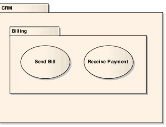
Figure 1: Use cases of billing subsystem
As a small running example of a software engineering artifact being represented as a graph, a minimalistic use case diagram introducing two use cases of the billing subsystem of a customer relationship management system: Send Bill and Receive Payment, respectively. In order to group the use cases with respect to the addressed (sub)system, so-calledRequirementsPackages are used (cf. figure 1).
3.1 TGraphs
TGraphsare directed graphs which are typed, attributed, and ordered. Since all elements, i.e.
vertices and edges have a type, appropriate light-weight conceptual modeling is directly sup-ported. Depending on their type, graph elements may carry attribute-value pairs which may be used for modeling data associated to them. The combination of types and attributes leads to an object-based style of modeling. Ordering of the vertices, the edges, and the incidences between vertices and edges also allows for a direct modeling of the sequences of occurrences of objects. In TGraphs, edges are first class citizens, i.e. they have all properties such as type and attributes, analogously to vertices. They may be stored in variables and their traversal is supported in both directions.
There is a highly efficient API for creating, manipulating, and traversing TGraphs: JGraLab2. There are several supporting technologies, as well, especially concerning schema support (cf. section 3.2) and querying (cf. section 3.4).
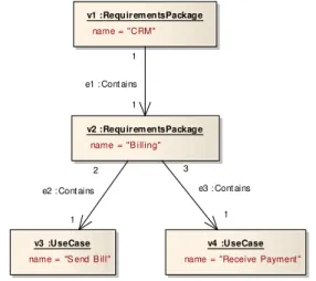
TGraphs may be used to store theabstract structureof software engineering artifacts and their traceable entities. Usually all relevant entities are modeled by vertices, and occurrences of enti-ties in some context are modeled by edges. Sequences of occurrences are expressed by the order of edges. v1 :Requir em entsPackage name = "CRM" v2 :Requir em entsPackage name = "B illing" v3 :UseCase name = "S end B ill"
v4 :UseCase name = "Receive Payment "
1 e3 : Cont ains 3 1 e2 : Cont ains 2 1 e1 : Cont ains 1
Figure 2: ASG for the use case diagram in figure 1
Figure 2 gives an example of a TGraph, sketched in the style of a UML object diagram. It contains four vertices and three edges forming a graph which can be viewed as an abstract syntax graph (ASG) of the sample use case diagram in figure 1. For illustrative purposes, the order of vertices and edges is represented by their identifiers: v1,v2, . . . ande1,e2, . . . , respectively. The order of incidences is displayed by the numbers resembling UML multiplicities.
3.2 Metamodeling TGraphs – grUML
Sets of TGraphs are specified by a subset of UML class diagrams as schemas. This UML sublan-guage is calledgrUML(graph UML) and contains all elements of UML class diagrams that are compliant with a graph-like semantics: classes represent vertex types and associations stand for edge types. The attributes of types are noted in UML style, too, where the notation of associated classes is used to specify edge attributes. Generalization/specialization is used for vertex and edge classes, as well, and multiple generalization is explicitly allowed. Finally, multiplicities are used to note degree restrictions. The modeling power of these kinds of diagrams is slightly higher than EMOF [Ebe08b, Obj06].
A TGraph iscompatibleto its schema, i.e. it constitutes an instance of the schema, if its element types and attribute assignments as well as the incidences of the edges respect the corresponding
Requir em entsPackage Requir ement
{abst ract}
UseCase
Component
Port Interface
Requirem entsSpecificationElem ent
{abst ract}
- name: St ring
PackageableE lement
{abst ract}
- name: St ring - vis ibilit y: Visibility Kind
NonFunctionalRequirement
satisfy ing 0..* Satis fies
sat isf ied 0..*
pac kagedE lement 0..* Owns 0. . 1 0..* Prov ides prov ided 0..* nes tedElement 0..* Cont ains
nest ingPack age 0. . 1
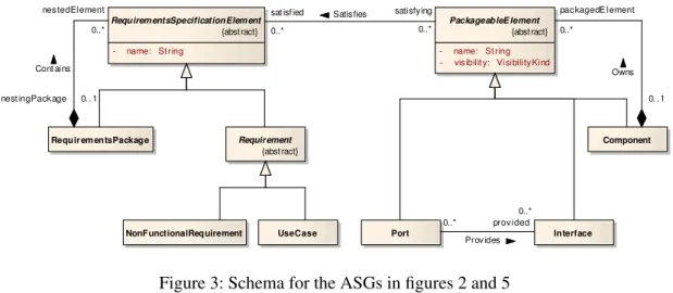
Figure 3: Schema for the ASGs in figures 2 and 5
descriptions in the schema and if the vertex degrees conform to the multiplicities. All these conditions must respect inheritance.
The notion of a TGraph schema is explained by means of the sample schema in figure 3. The left part of this schema constitutes a suitable metamodel for the ASG in figure 2. In addition to that, it contains an excerpt of the UML metamodel along with theSatisfiesedge class, applicable for modeling and tracing architecture elements generated from the use cases (cf. section 3.3).
3.3 Transforming TGraphs – MOLA
Transformationsof software engineering artifacts can be defined on the basis of their abstract
syntax, i.e. their TGraphs. A transformation system that is compatible with TGraph modeling and JGraLab is the MOLA-Tool which has been developed by the University of Latvia [Kal04]. MOLA is a programmable graph transformation language, which builds on rules consisting of a pattern and some actions and adds control structures – mainlyloops– to control the execution of these rules. A MOLA transformation consists of one or more MOLA procedures. A procedure connects a start node to an end node via some executable vertices.
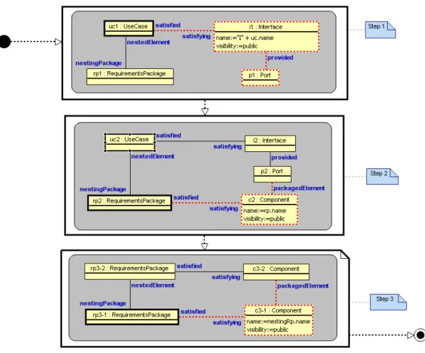
Figure 4 shows an example of a MOLA transformation that takes the ASG of figure 2 and extends it by adding corresponding architecturalComponents,Ports,Interfaces and traceability links, respectively – leading to the graph depicted in figure 5. This example contains three loops (large bold rectangles) each of which iterates a rule. Rules are expressed by gray rectangles with rounded corners. Each rule has one small bold rectangle which denotes a graph vertex and some light black edges and vertices which together specify the context of the particular vertex. The loop iterates over all instances in the graph that match this vertex and its context. For each instance the red dashed vertices and edges are added to the graph.
Figure 4: Rule for transforming requirements to architecture
Step 1: For eachUseCaseuc1which is nested in aRequirementsPackagerp1, an Inter-facei1and aPortp1 is created. i1is connected touc1by aSatisfiesedge. AProvides edge connectsp1toi1.
Step 2: For eachRequirementsPackagerp2nesting aUseCaseuc2handled in step 1 (i.e. a correspondingInterfacei2andPortp2was generated), aComponentc2is created. It is linked torp2andp2bySatisfiesandOwnsedges, respectively.
Step 3: For eachRequirementsPackagerp3-1nesting anotherRequirementsPackage rp3-2which is connected to a satisfyingComponentc3-2, anotherComponentc3-1is created, linked toc3-2by anOwnsedge.
Applying this MOLA-transformation to the graph presented in figure 2 results in the graph shown in figure 5, which itself complies to the graph schema given in figure 3.
v1 :Requir em entsPackage name = "CRM" v2 :Requir em entsPackage name = "B illing" v3 :UseCase name = "SendBill" v4 :UseCase name = "Rec eiv eP ayment "
v5 :Com ponent name = "CRM" v6 :Com ponent name = "B illing" v7 :Port v8 :Port v9 :Interface name = "I S endB ill"
v10 :I nterface name = "IRec eiv ePayment "
1 e10 :S atisfies
2 1
e9 : Sat isf ies 2 1 e12 :S atisfies 2 1 e11 :S atisfies 4 3 e6 : Owns 1 2 e5 : Owns 1 4 e4 : Owns 2 2 e8 :P rov ides 1 2 e7 :P rov ides 1 1 e3 : Cont ains 3 1 e2 : Cont ains 2 1 e1 : Cont ains 1
Figure 5: Resulting graph after transformation
3.4 Querying TGraphs – GReQL
Complementing the graph-based approach for the definition of traceability relationships based on grUML, its identification using MOLA transformations, its recording as a TGraph, and its utilization and maintenance using algorithms on TGraphs, a special TGraph query language, namedGReQL(Graph Repository Query Language) [Kul99] is provided, which allows the re-trieval of all kinds of information out of the graph repository.
GReQL is an expression language which describes the data to be retrieved from a given graph by nested expressions. The most important kind of expression is thefrom-with-report expres-sion which returns the data described in thereport-clause as a bag. The bag is constructed by deriving all instances of the variables described in thefrom-clause which fulfill the constraint given in thewith-clause.
In order to compute the bag of the name attributes of all vertices of type Interface that are connected to a vertex of typeUseCasevia aSatisfieslink, where the latter has the string"Send Bill"as itsnameattribute, a suitable GReQL query might look as follows:
from u:V{UseCase}, i:V{Interface}
with u.name = "Send Bill"
and u <--{Satisfies} i
report i.name
Expressions in GReQL may make use of regular path expressions to denote more complicated connections in the graph. As an example the names of all outerComponents, i.e. which are not contained by otherComponents are computed by the following query. A further condition is that theComponents directly or indirectly contain aPortwhich provides anInterfacesatisfying a givenUseCase.
from u:V{UseCase}, c:V{Component}
with u.name = "Receive Payment"
and u <--{Satisfies}<--{Provides} <--{Owns}* c
and indegree(c) = 0
report c.name
GReQL is an elaborate language and comes with an optimized query evaluator that works on TGraphs [Hor09].
4 Defining and Recording Traceability Information
As a first building block towards a comprehensive and seamless traceability approach, means to define and to record traceability information from any abstraction level must be available. These two activities are closely related because depending on the defined characteristics of traceability relationships, specific requirements are imposed on the recording technology.
In section 4.1, theTraceability Reference Schema(TRS), a reference schema, or reference meta-model, for traceability spanning all abstraction levels of a software development process, is introduced. The following section 4.2 describes the repository concept as a means of externally recording traceability information and details the implementation of a concrete, graph-based repository technology. In section 4.3, it is shown how in ReDSeeDS, so-calledsoftware cases, conforming to an application-specific adaptation of the TRS, are stored in a graph-based reposi-tory.
4.1 The Traceability Reference Schema
In accordance with the goals and characteristics of reference models [Win00], theTRSrepresents a generally applicable and adaptable metamodel for defining traceability relationships and traced entities, spanning different levels of abstraction from requirements specification to source code, test cases, and documentation. The TRS is modeled by using grUML, allowing for the modeling of traceability relationships as TGraph edges which may be specialized and may carry attributes. Adapted from the requirements reference metamodel in [Sch08], thecorepackage of the TRS depicted in figure 6 distinguishes betweenTraceableEntitieson the one hand and TraceabilityRe-lationships connecting twoTraceableEntitys in the roles ofsourceandtargeton the other hand. Theentitiespackage contains specializations ofTraceableEntitycovering different levels of
ab-Traceabl eE nti ty
{abst ract}
- id: I nteger - name: St ring - version: Int eger
Traceabi lityRelationship
{abst ract} source 0..*
Traceabilit y Relat ions hip
target 0. .*
Figure 6: Thecorepackage of the TRS
straction. A possible selection of such specializations is shown in figure 7. Depending on the specific application, the generalization hierarchy of TraceableEntity is to be modified accord-ingly. The specializations ofRequirementandCodeElement exemplify how to refine the TRS in order to achieve a finer level of granularity.
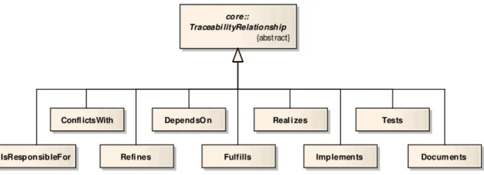
Concrete traceability relationship types are defined by specializingTraceabilityRelationship in therelationshipspackage, illustrated in figure 8. TraceabilityRelationship is defined in figure 7 by using an associated class, leading to the definition of an edge class. Thus, following the grUML semantics, all specializations in figure 8 define edge classes as well.
Relationship types may be restricted with respect to the entity types they are able to connect. The example in figure 9 shows that traceability relationships of typeIsResponsibleForconnect anyTraceableEntityto theStakeholdersresponsible for their creation or maintenance. Besides,
Requir ement - priority : I nt eger - liabilit y: I nt eger - stat us: Int eger - text : String
FunctionalRequirem ent NonFunctionalRequirement
TestCase - sit uation: St ring - event : St ring - expec tedResult : St ring
CodeElem ent
Cl ass
Method DesignEl ement
Fi el d ArchitectureE lem ent
core:: Traceabl eE nti ty
{abst ract}
- id: I nteger - name: St ring - version: Int eger
Stakeholder - af filiat ion: S tring
DocumentationE lem ent
member 0..* 1
member 0..* 1
core:: Traceabi lityRelationship {abst ract} Confl ictsWith Fulfills DependsO n
Refi nes Implements
Real i zes Tests
Docum ents IsResponsibleFor
Figure 8: Therelationshipspackage of the TRS
IsResponsibleForfeatures two attributes: established andrationale, holding the relationship’s creation time and a justification for its existence, respectively.
Similar to TraceableEntity, specializations ofTraceabilityRelationship have to be created when adapting the TRS to suit specific applications.
4.2 Implementation – Graph-based Repositories
Adaptations of the TRS reference schema can be used for defining which traceability links are expected to be identified in a given software engineering project, exemplified based on ReD-SeeDS in section 4.3.
grUML schemas are regarded as beingtool-ready, i.e. they serve as the data schema language in tools. This property is hard to achieve with metamodels conforming to full CMOF and was the main reason for the introduction of EMOF. Similarly, grUML was purposely defined as UML subset to provide tool-readiness. Thus, all relevant information on software engineering
arti-entiti es::Stakehol der - af filiat ion: S tring
core:: Traceabl eE nti ty
{abst ract}
- id: I nteger - name: St ring - version: Int eger
Traceability Relat ionship
rel ationships:: IsResponsibleFor - es tablis hed: Dat eTime - rationale: St ring stakeholder 0..* IsRes ponsibleFor entity 0..*
facts can be stored in afact repositorydirectly corresponding to a grUML schema, keeping the abstract syntax of all relevant documentsandtheir interconnections by traceability relationships. The repository is populated by a set of fact extraction tools which derive the facts from the respective artifacts. Fact extractors are usually fast enough to be applied regularly to the artifact base in order to generate the corresponding facts, but there are also incremental approaches which allow to replace an artifact’s subgraph in the repository [Kam98] on the fly.
JGraLab is especially suited to implement fact repositories, based on grUML as its schema language. Since grUML is a proper subset of UML supplied with a formal graph semantics, any standard-compliant UML tool can be used to edit schemas. Only minor transformations, e.g. replacing associations between associations, which contradict a pure graph interpretation, by appropriate new classes, are necessary to make MOF-like metamodels tool-ready using grUML. In ReDSeeDS, fact extraction is done by using the API of a UML tool3 in order to convert respective models into TGraphs. As result, one integrated graph is delivered which contains all information relevant for retrieving and utilizing traceability (cf. section 6).
Using grUML and JGraLab as repository technology allows for the use of GReQL as repository query language which is especially suited to support transitive closure efficiently using its regular expressions. (see section 6.2 and 6.3)
4.3 Application – Software Cases in ReDSeeDS
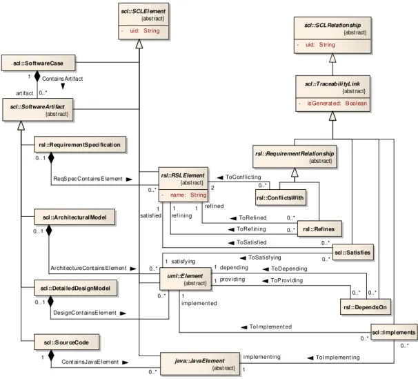
In ReDSeeDS, so-calledsoftware cases [ ´Smi06] comprise all artifacts created in conjunction with single development projects. A small simplified excerpt of the schema of theSoftware Case
Language (SCL) used to formulate such software cases is shown in figure 10. For modeling
entities on the four supported levels of abstraction – requirements specification, architecture, detailed design, and source code – the SCL integrates three sublanguages: the Requirements
Specification Language(RSL) [Kai07],UMLfor creating architecture and detailed design, and
Java[Gos05]. MOLA is employed for performing model transformations from requirements to architecture to detailed design and finally to source code (cf. section 5).
Comparing the SCL schema to the TRS, the SCL can be regarded as an adaptation of the TRS:SCLElementandSCLRelationshipin the SCL can be directly mapped toTraceableEntity andTraceabilityRelationship in the TRS. The metamodels of RSL, UML, and Java are plugged into the schema by modeling the topmost classes of the respective generalization hierarchies, RSLElement,Elementfrom UML, andJavaElement, as specializations ofSCLElement.
However, concerning traceability, note that instead of using EdgeClasses as in the TRS, an SCLRelationshipis modeled as aVertexClass together with twoEdgeClasses connecting it to the SCLElements to be related. This design decision was made due to the technical integra-tion of JGraLab with the transformaintegra-tion language MOLA (cf. secintegra-tion 5.2). Furthermore, SCL contains some SCLRelationships which are not relevant for traceability, thus necessitating the specialization ofSCLRelationshipbyTraceabilityLink.
scl ::SoftwareCase
scl::SoftwareArti fact
{abst ract}
rsl ::RequirementSpeci ficati on
scl ::Architectur al Model
scl ::Detai ledDesi gnModel
scl ::S our ceCode
scl::SCLEl ement
{abst ract}
- uid: S tring scl::SCLRelationship{abst ract}
- uid: S tring rsl::RSLElement {abst ract} - name: St ring uml::E lement {abst ract} scl ::Traceabili tyLink {abst ract}
- is Generat ed: B oolean
java::JavaElement {abst ract} scl ::Satisfi es scl ::I mpl ements rsl ::DependsOn rsl::RequirementRelationship {abst ract} rsl::Confli ctsWith rsl ::Refines 0..* ToSatisf ying satisfy ing 1 0..* ToSatisf ied
sat isf ied 1 0..* ReqS pec Cont ains E lement 0. . 1
0..* ToDepending
depending 1 1 Contains Art ifact
art ifact 0..*
0..* Cont ainsJ av aE lement
1
0..* Archit ec tureCont ains Element 0. . 1
0..* DesignCont ainsE lement
0. . 1 0..* ToI mplement ed implement ed 1 implement ing 1
ToI mplement ing
0..* 0..* ToRefined ref ined 1 0..* ToRef ining ref ining 1 0..* ToConf lic ting 2
0..* ToP rov iding
prov iding 1
Figure 10: The SCL schema
Concrete inter-level traceability relationship types are Satisfies, IsDependentOn, and Imple-ments, connecting anRSLElementwith a satisfying architecture UMLElement, an architecture UMLElementwith a depending detailed design UMLElement, and a detailed design UML El-ementwith an implementing source codeJavaElement, respectively. Examples for intra-level relationship types are the subclasses ofRequirementRelationshipfor connectingRSLElements. Since JGraLab is employed as common repository technology in ReDSeeDS, it is also used for recording traceability information. The choice of JGraLab over other technologies such as relational databases and ontologies is based on various criteria relevant for the project [Bil07a]. Among them are the possibility to integrate with model transformation facilities, the suitability for calculating similarity between requirements, and the expressiveness of available querying mechanisms.
5 Identifying and Maintaining Traceability Information
By defining a schema for traceability information and selecting an adequate recording infrastruc-ture, the prerequisites for instantiating concrete traceability relationships are met. Subsequently, identification techniques have to be applied in order to create a population of such relationships, be it either manually or (semi-)automatically. As mentioned in section 2.2, similar techniques can be used to maintain already existing relationships.
Section 5.1 generally introduces the identification and maintainance of traceability relationships in a model-driven context, i.e. employing model transformations. In section 5.2, the technical integration of the transformation language MOLA with JGraLab as a graph-based repository for traceability information is described. Finally, section 5.3 exemplifies the approach on the basis of ReDSeeDS by automatically generating traceability relationships between requirements, architecture, and design in the course of respective transformations.
5.1 Identifying and Maintaining Traceability Relationships with Model Transformations
There exist various concepts for drawing on model transformations in order to aid in the auto-matic identification of traceability relationships. A closer look at these concepts reveals that they rely on the generation of traceability relationshipsin the course of model transformation execu-tion. However, another thinkable approach is to derive traceability relationshipssubsequent to
model transformation execution, based on the employed transformation rules.
Regarding the common approach, users are typically required to explicitly encode the genera-tion of relagenera-tionships within transformagenera-tion rules (see, for example, [Jou05]). Alternatively, ap-proaches such as OMG’s QVT [Obj08] propose to automatically create traceability relationships between source and target entities of model transformations.
Maintenance of traceability relationships using model transformations is usually triggered by the reexecution of transformation rules upon the change of one of the entities in the source model. However, this results in discarding the previous target model and generating a new one, naturally entailing the regeneration of all traceability relationships. A more sophisticated approach is to selectively update only those entities of the target model which are affected by the change, referred to asincremental updateby QVT. Existing relationships between changed source and target entities could then be updated accordingly.
5.2 Implementation – Using MOLA for Traceability Relationship Generation and Maintenance
The usage of the TGraph approach as foundation for handling traceability information, espe-cially with the intention to identify traceability relationships based on model transformations, necessitates the incorporation of an adequate transformation language. In the course of the ReD-SeeDS project, the MOLA transformation language and its underlying technology proved to be
a suitable candidate for an integration with JGraLab. Besides some technical issues, the main reason for this decision was that the meta-metamodel of MOLA is similar to EMOF [Kal05], whose modeling power can in turn be compared to grUML.
In EMOF, however, there is no direct equivalent for attributedEdgeClasses which possibly stand in a generalization hierarchy. Therefore, as shortly explained in section 4.3, it is necessary to model a traceability relationship as a VertexClass in conjunction with twoEdgeClasses con-necting it to the traced entities to be related (cf. figure 10). This allows for a corresponding representation in EMOF by employingClasses with respectiveProperties.
Having a schema usable by both JGraLab and MOLA, there exist two basic alternatives for accomplishing the technical integration. On the one hand, it is possible to establish a map-ping between the contents of the JGraLab repository and the internal repository of the MOLA
transformation execution environment. Due to its straightforwardness, this approach was
im-plemented for obtaining a first solution. Since MOLA technology is imim-plemented in C++,Java
Native Interface(JNI) or JGraLab’s XML-RPC interface has to be employed in order to facilitate
such an integration [Kal07].
On the other hand, latest integration efforts showed that MOLA transformations could be directly compiled to work on JGraLab as repository, thus avoiding the need to maintain two repositories [Sos08]. Consequently, this approach has emerged as being the integration alternative of choice.
5.3 Application – Generating Traceability Relationships in ReDSeeDS
The ReDSeeDS project features the automatic transformation of software cases’ requirements specifications to architectural models and further on to detailed design models and source code. Generally, this transformation-based approach is applicable for any architectural style. However, the transformation of a requirements specification to the common4-tier architecture, consisting of presentation, application logic, business logic, and data storage tiers, has been chosen for a prototypical development in ReDSeeDS.
A simplified example illustrating the creation of an application tierComponent together with its Interfaces is described in section 3. As shown in figure 5, architecture entities and their originating entities of the requirements specification level are linked by Satisfiestraceability relationships. Other transformations from requirements to architecture include the generation of business tier components from the requirements specification’s vocabulary and the creation of application and business logic tier interface operations from RSL scenario descriptions [Boj08]. Going on to detailed design, transformations serve to add further details to the architecture model, such as factory classes and implementation classes for the previously generated inter-faces. Here,DependsOninstances serve to represent traceability relationships between corre-sponding architecture and design entities. Finally, instances ofImplementsdenote traceability relationships between Java source code fragments and their originating detailed design entities. Altogether, ReDSeeDS features about forty MOLA procedures realizing these transformations, each one consisting of several rules [Kal07].
Maintenance of traceability relationships is envisioned to be eased by marking elements of trans-formations’ target models which have been manually changed afterwards. Upon a subsequent change to the source model, developers would be asked if the manually changed target ele-ments shall be overwritten in the course of the reexecution of the transformation [Kal07]. The traceability relationships connecting elements which are not overwritten then are candidates for (manual) maintenance, for it is up to the developers to decide whether the relationship between source and target element is still valid.
6 Retrieving and Utilizing Traceability Information
Once a repository has been populated with traceability information, be it by model transforma-tions as described in section 5 or by other techniques, sought-for traceability information can be retrieved for visualization or other utilizations.
Section 6.1 introduces three patterns which categorize “typical” problems observable when deal-ing with traceability information retrieval, together with possible fields for utilization. In addi-tion to the general problem statements, the patterns also feature generic queries acting as possible solutions. Therefore, section 6.2 further elaborates on the patterns by giving a selection of such queries formulated in GReQL, including some details on GReQL’s implementation. Conclud-ing, section 6.3 shows the concrete retrieval problem addressed in ReDSeeDS and the utilization of the so-calledslicepattern in order to solve this problem.
6.1 Common Retrieval Patterns
An analysis of various industrial application for traceability has been conducted in theMOST
project4, leading to a collection of requirements towards the traceability approach to be devel-oped in that project. Based on these requirements, often recurring problems dealing with the retrieval of traceability information could be identified. It is possible to abstract these problems into threepatternsfor retrieval. A look at traceability-related literature reveals that many of the traceability problems described therein can be mapped to one of these patterns:
• existence
• reachable entities
• slice
The first pattern, namedexistence, treats the question whether there exists a path of traceability relationships between any two traced entities out of given sets of such entities. More formally, the condition is fulfilled if, given two sets of traced entitiesEe1andEe2, there existee1∈Ee1and
ee2∈Ee2with a path of traceability relationships betweenee1andee2. Instead of accepting any
path betweenee1andee2, in many cases it is required to restrict eligible paths with respect to the
sequence, direction, or type of the involved traceability relationships. These constraints are, for example, expressible by regular path descriptions.
An important area of application for the existence pattern is quality assurance, e.g. in order to check whether there exists a realizing architecture component for each requirement. Conversely, investigating if every design element or source code fragment can be traced back to a requirement avoidsgold plating[Jar98], i.e. the implementation of unneeded features. Another usage is to test every design class for the existence of a dedicated test case.
Reachable entitiesis concerned with the determination of all traced entities which are reachable
from a given set of entities: Given a set of traced entities Er1, the set Er2 of traced entities
reachable from someer1∈Er1by following a path of traceability relationships is to be computed. Similar to the existence pattern, most often it is reasonable to impose various constraints on the structure of the paths which are to be taken into account. It is important to understand that only those entitiesat the endof a path are part ofEr2. This aspect makes no difference as long as any path is accepted. But restricting the eligible paths to those of length two, i.e. consisting of two traceability relationships, for instance, would result in intermediate entities not to be included in
Er2.
Ranging from change management and maintenance to reverse engineering and project man-agement, the variety of applications for the reachable entities pattern is manifold. Two concrete examples are the detection of Java classes implementing a specific system component and the determination of stakeholders in order to clarify open questions on particular requirements. The third pattern,slice, resembles the reachable entities pattern, with the distinction that not only the “endpoints” of a path of traceability relationships, but also all intermediate entities lying on that path and their interconnecting relationships are of interest. More precisely, given set of traced entitiesEs1, the set of traced entitiesEs2 incorporated by a so-calledslice corresponds to the set of all entities lying on paths starting at some entityes1∈Es1. Furthermore, the slice
also contains the relationships which are part of the regarded paths. Naturally, restrictions of the paths to be considered play an important role here, too. Referring to graph terminology, a slice is effectively a subgraph of the graph formed by the entirety of traced entities and their interconnecting traceability relationships.
The breadth of possible applications of the slice pattern strongly overlaps with that of the reach-able entities pattern. However, there exist many specific use cases which profit from the addi-tional information on intermediate entities provided by a slice. A typical usage is the analysis of a traced entity’s origins, i.e. to determine which entities have played a role in the creation of that particular entity. Another application, the reuse of software artifacts as pursued by ReDSeeDS, is presented in more detail in section 6.3.
6.2 Implementation – Retrieval with GReQL
GReQL, the Graph Repository Query Language, is tightly integrated with JGraLab and conse-quently the main candidate for retrieval of traceability information stored in a graph-based repos-itory. As sketched in the following, GReQL proves to be well-suited for formulating queries
capable of dealing with the problems represented by the three traceability retrieval patterns. The example queries are based on the transformed graph in section 3.3.
Starting with the existence pattern, the following GReQL query checks if everyUseCasecan be traced to anInterfaceby aSatisfiesrelationship:
forall u:V{UseCase} @ exists i:V{Interface}
@ u <--{Satisfies} i
This query does not make use of from-with-report expressions, but directly uses a quantified
expressionreturning a boolean value. Obviously, looking at the graph in figure 5, the result of
this query istrue.
When intending to apply the reachable entities pattern, the GReQL feature forward vertex set
can be employed: The query below returns all vertices which can be reached from vertexv1by following a path of arbitrary length whose edges are of any type and direction.
v1 <->*
Naturally, this will result in all vertices, i.e. traced entities, somehow reachable fromv1to be returned by that query. Note that for reasons of brevity, the binding of the variables to vertices, e.g. the representation of vertexv1taken from the example graph by the variablev1, is omitted in this and following queries.
The expressiveness of regular path descriptions supported by GReQL is useful for narrowing the selection of paths to be taken into account when applying the reachable entities pattern:
v6 -->{Owns}-->{Provides}
This query serves to get the set ofInterfaces{v9,v10}which is provided byPorts owned by the Component v6.
For computing slices, GReQL offers a dedicated function calledslice, taking a set of vertices and a regular path expression as parameters. In analogy with the program slicing approach [Wei84], the combination of these input parameters is calledslicing criterion:
slice(set(v3, v4),
<--{Satisfies}<--{Provides}<--{Owns})
The slice returned by the query above yields theUseCasesv3andv4together with their satis-fyingInterfaces, thePorts providing them, and the owningComponent. This corresponds to the subgraph consisting of the set{v3,v4,v6,v7,v8,v9,v10}of vertices and the set{e5,e6, e7, e8,e9,e10}of edges.
GReQL queries are evaluated by first parsing them and representing their abstract syntax as di-rected, acyclic TGraphs. Subsequent to potential optimizations, the syntax graphs are evaluated by synthesizing the results of specific vertices from the results of their child vertices. In order to evaluate regular path expressions, deterministic finite automatons are built based on the path
expressions. Although theoretically, the number of states of such an automaton may explode ex-ponentially, the used algorithms are known to be benevolent. So this will generally only happen with artificial examples. Finally, the DFAs are used to drive the traversal of the graph and to mark relevant vertices and edges. [Ebe08a]
6.3 Application – Slicing in ReDSeeDS
The slicing approach can be employed for finding reusable software artifacts in ReDSeeDS. The slicing criterion consists, on the one hand, of a given set reqs, denoting traced entities representing requirements of a past software case identified to be similar to requirements of a current software case. On the other hand, the regular path expression is tailored to retrieve all entities of the past software case which are responsible for realizing one or more of the given requirements.
ReDSeeDS distinguishes between three different notions of a slice:maximal slice,minimal slice,
andideal slice [Amb08]. While maximal slices include every traced entity somehow related
to a requirement in reqs, minimal slices almost exclusively consider inter-level traceability relationships, only taking into account intra-level relationships on the requirements level. A GReQL query computing such a minimal slice might look as follows:
slice(reqs , (<--{ToRefined}-->{ToRefining})* <--{ToSatisfied}-->{ToSatisfying}
<--{ToDepending}-->{ToProviding}
<--{ToImplemented}-->{ToImplementing})
As it can be gathered from this query, the path expression considers inter-level traceability re-lationships, i.e.Satisfies,DependsOn, andImplements, as well as theRefinesintra-level rela-tionship in order to involve requirements which do not belong to those in thereqsset, but are closely related to them (cf. figure 5).
However, both maximal and minimal slices are likely to not meet users’ expectations: Maximal slices probably are equivalent to the whole software case. Minimal slices ignore entities on the architecture, design, or code level which are not directly linked to some requirement, but which are important because entities within the minimal slice depend on them.
Therefore, the concept of ideal slice tries to formulate a suitable path expression for capturing entities which are essential for the proper functioning of entities directly linked to requirements by inter-level relationships. Due to the complexity of the SCL schema, of which figure 5 shows only an excerpt and omits many intra-level relationships, these path expressions are very intri-cate. More information can be found in [Bil07b].
7 Conclusion
This paper introduces the TGraph-based approach for formalizing and implementing of trace-ability information in software engineering projects. The TGraph-approach for tracetrace-ability man-agement was developed and realized in the ReDSeeDS project which aims at the support of software reuse based on similarity of requirement definitions. In order to derive reusable soft-ware elements, a comprehensive and seamless approach for all traceability related activities was requested. TGraph-based graph-technology provides a comprehensive and smoothly integrated means to traceability management comprising all traceability-related activities during software development and maintenance.
TGraph-based metamodeling, using an adaptable and extensible reference structure for defining traceability information via grUML-class diagrams provides a formal description of project rel-evant traceability data. Coincidentally, these metamodelsdefinegraph based data structures to
recordtraceability information in the JGraLab-graph repository. Graph-based transformations,
using the MOLA modeling transformation engine, are used toidentifyandmaintain traceabil-ity information, and graph queries, using the GReQL graph query engine, support efficient and comprehensiveretrievalandutilizationof traceability interrelations.
Applying the approach to real development projects, contributed by various industrial partners in the ReDSeeDS project, facilitated the development and validation of an applicable technique for traceability management
Acknowledgements This work has been partially funded by the European Commission within the 6th Framework Programme project ReDSeeDS, no. IST-2006-33596,http://www.redseeds.eu, and the 7th Framework Programme project MOST no. ICT-2008-216691,http://most-project. eu.
References
[Aiz05] AIZENBUD-RESHEF, Netta ; PAIGE, Richard F. ; RUBIN, Julia ; SHAHAM-GAFNI, Yael ; KOLOVOS, Dimitrios S.: Operational Semantics for Traceability. In: ECMDA Traceability Workshop (ECMDA-TW) 2005 Proc., 2005
[Aiz06] AIZENBUD-RESHEF, N. ; NOLAN, B. T. ; RUBIN, J. ; SHAHAM-GAFNI, Y.: Model traceabil-ity. In:IBM Systems Journal 45 (2006), Nr. 3, S. 515–526
[Ama08] AMAR, Bastien ; LEBLANC, Herv´e ; COULETTE, Bernard: A Traceability Engine Dedi-cated to Model Transformation for Software Engineering. In:ECMDA Traceability Workshop (ECMDA-TW) 2008 Proc., 2008, S. 7–16
[Amb08] AMBROZIEWICZ, Albert ; BOJARSKI, Jacek ; NOWAKOWSKI, Wiktor ; STRASZAK, Tomasz: Can Precise Requirements Models Drive Software Case Reuse? In: Proceedings of the 2nd International Workshop on Model Reuse Strategies (MoRSe 2008), 2008, S. 27–34
[Ant01] ANTONIOL, G. ; CANFORA, G. ; CASAZZA, G. ; DE LUCIA, A.: Maintaining traceability links during object-oriented software evolution. In: Softw. Pract. Exper. 31 (2001), Nr. 4, S. 331–355. – ISSN 0038–0644
[Ant02] ANTONIOL, Giuliano ; CANFORA, Gerardo ; CASAZZA, Gerardo ; DE LUCIA, Andrea ; MERLO, Ettore: Recovering Traceability Links between Code and Documentation. In:IEEE Trans. Softw. Eng.28 (2002), Nr. 10, S. 970–983
[Asu07] ASUNCION, Hazeline U. ; FRANC¸OIS, Fr´ed´eric ; TAYLOR, Richard N.: An End-To-End Industrial Software Traceability Tool. In: ESEC-FSE ’07: Proc. of the the 6th joint meeting of the European Software Engineering Conference and the ACM SIGSOFT symposium on the Foundations of Software Engineering. New York, NY, USA : ACM Press, 2007, S. 115–124 [Bil07a] BILDHAUER, Daniel ; EBERT, J¨urgen ; RIEDIGER, Volker ; KREBS, Thorsten ; NICK, Markus
; SCHWARZ, Hannes ; KALNINS, Audris ; KALNINA, Elina ; NICK, Markus ; SCHNEICKERT, S¨oren ; CELMS, Edgars ; WOLTER, Katharina ; AMBROZIEWICZ, Albert ; BOJARSKI, Jacek: Repository Selection Report / ReDSeeDS Project. 2007 ( D4.4). – Project Deliverable [Bil07b] BILDHAUER, Daniel ; EBERT, J¨urgen ; RIEDIGER, Volker ; WOLTER, Katharina ; NICK,
Markus ; JEDLITSCHKA, Andreas ; WEBER, Sebastian ; SCHWARZ, Hannes ; AM
-BROZIEWICZ, Albert ; BOJARSKI, Jacek ; STRASZAK, Tomasz ; KAVALDJIAN, Sevan ; POPP, Roman ; SZEP, Alexander: Software Case Marking Language Definition / ReDSeeDS Project. 2007 ( D4.3). – Project Deliverable. www.redseeds.eu
[Bil08] BILDHAUER, Daniel ; EBERT, J¨urgen ; RIEDIGER, Volker ; SCHWARZ, Hannes: Using the TGraph Approach for Model Fact Repositories. In: Proc. of the Second International Work-shop MoRSe 2008, 2008, S. 9–18
[Boj08] BOJARSKI, Jacek ; STRASZAK, Tomasz ; AMBROZIEWICZ, Albert ; NOWAKOWSKI, Wiktor: Transition from precisely defined requirements into draft architecture as an MDA realisation. In:Proceedings of the 2nd International Workshop on Model Reuse Strategies (MoRSe 2008), 2008, S. 35–42
[Car01] CARLSHAMRE, P¨ar ; SANDAHL, Kristian ; LINDVALL, Mikael ; REGNELL, Bj¨orn ; NATT OCH
DAG, Johan: An Industrial Survey of Requirements Interdependencies in Software Product Release Planning. In:RE ’01: Proc. of the Fifth IEEE International Symposium on Require-ments Engineering, 2001
[Cle03a] CLELAND-HUANG, Jane ; CHANG, Carl K. ; CHRISTENSEN, Mark: Event-Based Traceability for Managing Evolutionary Change. In:IEEE Trans. Softw. Eng.29 (2003), Nr. 9, S. 796–810 [Cle03b] CLELAND-HUANG, Jane ; SCHMELZER, David: Dynamically Tracing Non-Functional Re-quirements through Design Pattern Invariants. In:Proc. of the 2nd International Workshop on Traceability in Emerging Forms of Software Engineering, 2003
[Con95] CONSTANTOPOULOS, Panos ; JARKE, Matthias ; MYLOPOULOS, John ; VASSILIOU, Yannis: The Software Information Base: A Server for Reuse. In:The VLDB Journal 4 (1995), Nr. 1, S. 1–43. – ISSN 1066–8888
[Cys08] CYSNEIROS, Gilberto ; ZISMAN, Andrea: Traceability and Completeness Checking for Agent-Oriented Systems. In:Proc. of the 2008 ACM symposium on Applied computing (SAC ’08), 2008, S. 71–77
[Dah03] DAHLSTEDT, ˚Asa G. ; PERSSON, Anne: Requirements Interdependencies - Moulding the State of Research into a Research Agenda. In:Requirements Engineering Forum on Software
Quality (REFSQ), 2003, S. 71–80
[De 07] DE LUCIA, Andrea ; FASANO, Fausto ; OLIVETO, Rocco ; TORTORA, Genoveffa:
Recover-ing Traceability Links in Software Artifact Management Systems usRecover-ing Information Retrieval Methods. In:ACM Trans. Softw. Engin. Method. 16 (2007), Nr. 4, S. 13. – ISSN 1049–331X [Dic02] DICK, Jeremy: Rich Traceability. In:Proc of the 1st International Workshop on Traceability
in Emerging Forms of Software Engineering, Edinburgh, 2002
[Dri08] DRIVALOS, Nicholas ; PAIGE, Richard F. ; FERNANDES, Kiran J. ; KOLOVOS, Dimitrios S.: Towards Rigorously Defined Model-to-Model Traceability. In: ECMDA Traceability Work-shop (ECMDA-TW) 2008 Proc., 2008, S. 17–26
[Ebe97] EBERT, J. ; S ¨UTTENBACH, R. ; UHE, I.: Meta-CASE in Practice: a Case for KOGGE. In:A. Oliv´e, J. A. Pastor (eds.): Advanced Information Systems Engineering, Springer, LNCS 1250. 1997, S. 203–216
[Ebe02] EBERT, J¨urgen ; KULLBACH, Bernt ; RIEDIGER, Volker ; WINTER, Andreas: GUPRO. Generic Understanding of Programs - An Overview. In:Electronic Notes in Theoretical Com-puter Science, http://www.elsevier.nl/locate/entcs/volume72.html72 (2002), Nr. 2
[Ebe08a] EBERT, J¨urgen ; BILDHAUER, Daniel: Querying Software Abstraction Graphs. In: Proceed-ings of Query Technologies and Applications for Program Comprehension (QTAPC 2008), 2008
[Ebe08b] EBERT, J¨urgen ; RIEDIGER, Volker ; WINTER, Andreas: Graph Technology in Reverse En-gineering, The TGraph Approach. In: GIMNICH, Rainer (Hrsg.) ; KAISER, Uwe (Hrsg.) ; QUANTE, Jochen (Hrsg.) ; WINTER, Andreas (Hrsg.): Proc. of the 10th Workshop Software Reengineering (WSR 2008)Bd. 126. Bonn : GI, 2008, S. 67–81
[Egy01] EGYED, Alexander: A Scenario-Driven Approach to Traceability. In: Proc. of the 23rd International Conference on Software Engineering, 2001, S. 123–132
[Esp06] ESPINOZA, Angelina ; ALARCON´ , Pedro P. ; GARBAJOSA, Juan: Analyzing and Systematiz-ing Current Traceability Schemas. In:SEW ’06: 30th Annual IEEE/NASA Software Engineer-ing Workshop SEW-30, 2006, S. 21–32
[Gok08] GOKNIL, Arda ; KURTEV, Ivan ;VAN DEN BERG, Klaas: Change Impact Analysis based on Formalization of Trace Relations for Requirements. In: ECMDA Traceability Workshop (ECMDA-TW) 2008 Proc., 2008, S. 59–75
[Gos05] GOSLING, James ; JOY, Bill ; STEELE, Guy ; BRACHA, Gilad: The Java Language Specifica-tion. 3. Prentice Hall, 2005
[Got94] GOTEL, Orlena C. Z. ; FINKELSTEIN, Anthony C. W.: An Analysis of the Requirements Traceability Problem. In:Proc. of the First International Conference on Requirements Engi-neering, Colorado Springs, CO, USA, IEEE Computer Society Press, April 1994, S. 94–102 [Gre07] GRECHANIK, Mark ; MCKINLEY, Kathryn S. ; PERRY, Dewayne E.: Recovering And
Us-ing Use-Case-Diagram-To-Source-Code Traceability Links. In:ESEC-FSE ’07: Proc. of the 6th joint meeting of the European Software Engineering Conference and the ACM SIGSOFT symposium on The Foundations of Software Engineering, 2007
[Haa04] HAARSLEV, Volker ; M ¨OLLER, Ralf ; WESSEL, Michael. Querying the Semantic Web with Racer + nRQL. 2004
[Hor09] HORN, Tassilo: Ein Optimierer f¨ur GReQL2. M¨unchen : Grin Verlag, 1. 2009. – ISBN 978–3640250561
[Huf06] HUFFMANHAYES, Jane ; DEKHTYAR, Alex ; SUNDARAM, Senthil K.: Advancing Candidate Link Generation for Requirements Tracing: The Study of Methods. In: IEEE Trans. Softw. Eng.32 (2006), Nr. 1, S. 4–19
[IEE90] IEEE:IEEE Standard Glossary of Software Engineering Terminology, IEEE Std 610.12-1990. 1990
[Jar98] JARKE, Matthias: Requirements Tracing. In:Communications of the ACM 41 (1998), Nr. 12, S. 32–36
[Jou05] JOUAULT, Fr´ed´eric: Loosely Coupled Traceability for ATL. In: ECMDA Traceability Work-shop (ECMDA-TW) 2005 Proc., 2005, S. 29–37
[Kai93] KAINDL, Hermann: The Missing Link in Requirements Engineering. In:SIGSOFT Software Engineering Notes18 (1993), Nr. 2, S. 30–39
[Kai07] KAINDL, Hermann ; ´SMIAŁEK, Michał ; SVETINOVIC, Davor ; AMBROZIEWICZ, Albert ; BOJARSKI, Jacek ; NOWAKOWSKI, Wiktor ; STRASZAK, Tomasz ; SCHWARZ, Hannes ; BILDHAUER, Daniel ; BROGAN, John P. ; MUKASA, Kizito S. ; WOLTER, Katharina ; KREBS, Thorsten: Requirements Specification Language Definition / ReDSeeDS Project. 2007 ( D2.4.1). – Project Deliverable
[Kal04] KALNINS, Audris ; BARZDINS, Janis ; CELMS, Edgars: Model Transformation Language MOLA. In:MDAFA: Model Driven Architecture: Foundations and Applications, 2004 [Kal05] KALNINS, Audris ; CELMS, Edgars ; SOSTAKS, Agris: Tool Support for MOLA. In:GraMoT:
Workshop on Graph and Model Transformation, GPCE’05, 2005, S. 162–163
[Kal07] KALNINS, Audris ; KALNINA, Elina ; CELMS, Edgars ; SOSTAKS, Agris ; SCHWARZ, Hannes ; AMBROZIEWICZ, Albert ; BOJARSKI, Jacek ; NOWAKOWSKI, Wiktor ; STRASZAK, Tomasz ; KAVALDJIAN, Sevan ; FALB, J¨urgen: Reusable Case Transformation Rule Specification / ReDSeeDS Project. 2007 ( D3.3). – Project Deliverable
[Kam98] KAMP, Manfred: Managing a Multi-File, Multi-Language Software Repository for Program Comprehension Tools — A Generic Approach / Universitt Koblenz-Landau, Institut fr Infor-matik. Koblenz, 1998 ( 1/98). – Forschungsbericht
[Kne02] VONKNETHEN, Antje ; PAECH, Barbara: A Survey on Tracing Approaches in Theory and Practice / Fraunhofer IESE. 2002 ( 095.01/E). – Forschungsbericht
[Kul99] KULLBACH, Bernt ; WINTER, Andreas: Querying as an Enabling Technology in Software Reengineering. In: VERHOEF, C. (Hrsg.) ; NESI, P. (Hrsg.):Proc. of the 3rd Euromicro Con-ference on Software Maintenance & Reengineering. Los Alamitos : IEEE Computer Society, 1999, S. 42–50
[Kur07] KURTEV, Ivan ; DEE, Matthijs ; GOKNIL, Arda ;VAN DERBERG, Klaas: Traceability-based Change Management in Operational Mappings. In:ECMDA Traceability Workshop (ECMDA-TW) 2007 Proc., 2007, S. 57–67
[Let02] LETELIER, Patricio: A Framework for Requirements Traceability in UML-based Projects. In:
Proc. of 1st International Workshop on Traceability in Emerging Forms of Software Engineer-ing, 2002, S. 173–183