Abstract - In the area of active power filtering, with an objective to reduce inverter capacity, the Series Hybrid Active Power Filter (SHAPF) has been taken into account increasingly. Existing method used for controlling SHAPF is either based on detecting source current harmonic or load voltage harmonics. Generalised Instantaneous Power Theory (GIPT) gives simple and direct method of defining power quantities under sinusoidal and non sinusoidal situations. The definition of GIPT is used to decompose voltage vector into different components, which represents different parts of the power quantity. The separated components of voltage vector are used to derive reference for SHAPF. This paper presents simulation study of SHAPF used for harmonic elimination, where the method used for calculating reference is based on GIPT. The mathematical formulation of proposed control scheme with its applications to SHAPF is presented. The validity of the proposed control scheme is verified by the simulation study.
Index Terms— Active filters, instantaneous power, geometric algebra, nonsinusoidal waveforms, power multivector.
I. INTRODUCTION
oad compensation in power engineering is the procedure used to obtain the supply currents that are sinusoidal and balanced. Active power line conditioners (APLCs) make it possible to obtain power-electronic solutions to power quality (PQ) problems. In particular, balanced or unbalanced load compensation in non-sinusoidal supply situations is possible [1].
Active Power Filter (APF) has become the main research direction of load compensation as its filtering characteristic is not affected by system parameters. Various APF configurations and control strategies have been researched during the last decades. So far, a large number of shunt APF have been installed, but there are still some shortcomings like large capacity, high initial investment, harmonic circulation while working with the shunt Passive Power Filter (PPF) together, improving filtering characteristic when the PPF makes the system resonance etc. In order to reduce inverter capacity, the hybrid APF is becoming very popular in recent development. A variety of configurations and control strategies are proposed to reduce inverter capacity [2-4].
M. A. Mulla, R. Chudamani, and A. Chowdhury are with the Department of Electrical Engineering, S. V. National Institute of Technology, Ichchhanath, Surat, Gujarat - 395007, INDIA. (e-mail: [email protected]).
To obtain efficient SHAPF performance, it is important to choose proper reference generation algorithm and an appropriate current or voltage control strategy. The publication of the instantaneous reactive power theory caused a great impact in reference generation. Many approaches have been published since then [5–16]. But all of these definitions are computational intensive and do not provide simple expression of instantaneous power quantity. In year 2004, X. Dai [17-20] introduced generalised instantaneous power theory which gives a direct and simple expression for instantaneous power quantities.
This paper presents a reduced rating SHAPF with a novel control algorithm for generating reference voltage using GIPT. It is proposed to decompose multiphase voltage vector into quantities that represents different components of power. Normally the instantaneous power has average component and oscillating component. Using vector algebra it is possible to obtain the voltage vectors corresponding to these average powers. The voltage vector corresponding to oscillating active and reactive power is used to calculate reference voltage for removing harmonics.
This paper is organized as follows. First, a generalized definition of instantaneous active, reactive and apparent power quantity is presented. Then, the proposed decomposition of voltage vector which represents different components of power quantities is defined. Further the use of this decomposition for calculating the reference for SHAPF is discussed for harmonic elimination. Finally, the application of proposed control scheme to SHAPF is presented.
II. DEFINITION OF GENERALIZED INSTANTANEOUS POWER
THEORY
This section represents the formulation of basic terms in Generalised Instantaneous Power Theory (GIPT) [17-20]. For a three-phase four-wire system, the instantaneous quantities of load voltage and currents are expressed as
[
]
Tc b a
v
v
v
v
r
=
,
,
andr
i
=
[
i
a,
i
b,
i
c]
T.The instantaneous power multi-vector which is defined as the geometric product of voltage and current vectors can be expressed as,
)
(
)
(
)
(
)
(
)
(
)
(
)
(
t
v
t
i
t
v
t
i
t
v
t
i
t
s
r
=
=
•
+
×
)
(
)
(
)
(
t
p
t
q
t
s
r
r
=
+
…. (1)Series Active Power Filter Using Generalised
Instantaneous Power Theory
M.A. Mulla, Member, IEEE, R. Chudamani, A. Chowdhury, Member, IEEE
Load instantaneous apparent power‘s’ is defined as
s
=
v
r
i
r
, wherev
r
=
v
a2+
v
b2+
v
c2 and2 2 2
c b
a
i
i
i
i
=
+
+
r
.
Load instantaneous active power ‘p’ is defined as the inner product of voltage and current vectors.
c c b b a a
T
i
v
i
v
i
v
i
v
t
i
t
v
t
p
(
)
=
r
(
)
•
r
(
)
=
=
+
+
…. (2)Load instantaneous reactive power
q
r
(
t
)
is defined as the outer product of voltage and current vectorq
r
(
t
)
=
v
r
(
t
)
×
i
r
(
t
)
. The outer product is defined by means of the tensor product asv
r
(
t
)
×
i
r
(
t
)
=
r
i
(
t
)
⊗
v
r
(
t
)
−
v
r
(
t
)
⊗
i
r
(
t
)
.⎥
⎥
⎥
⎦
⎤
⎢
⎢
⎢
⎣
⎡
−
−
−
=
×
=
0
0
0
)
(
)
(
)
(
bc ca bc ab ca abq
q
q
q
q
q
t
i
t
v
t
q
r
r
r
…. (3)with each components being defined as,
c a a c ca b c c b bc a b b a
ab
v
i
v
i
q
v
i
v
i
q
v
i
v
i
q
=
−
;
=
−
;
=
−
) (t
qr is denoted as instantaneous reactive tensor and its norm is defined as instantaneous reactive power
2 2 2
ca bc
ab
q
q
q
q
r
=
+
+
…. (4)III. PROPOSED METHOD OF REFERENCE GENERATION
In the proposed method, the calculation of reference signal for SHAPF is performed in two steps (i) decomposition of voltage vector into different components, which represents different components of the power quantityand (ii) generating reference voltage corresponding to unwanted components of power quantity.
A. Decomposition of Voltage Vector
Using (1) representing voltage with two components, one in phase with current and another quadrature to the current, the apparent power
s
r
(
t
)
can be written asr
s
(
t
)
=
[
v
r
p(
t
)
+
v
r
q(
t
)]
•
r
i
(
t
)
+
[
v
r
p(
t
)
+
v
r
q(
t
)]
×
i
r
(
t
)
. After simplification we obtain) ( ) ( ) ( ) ( ) ( ) ( )
(t v t i t v t i t p t q t
s p q r
r r r r
r = • + × = + … (5)
Using the first part of (5), the component of load instantaneous voltage vector ‘
v
r
p’, corresponding to active power can be expressed as(
)
1(
)
2p
(
t
)
i
i
t
p
i
t
v
pr
r
r
r
=
−=
.[
]
[
]
Tc b a T pc pb pa
p i i i
i t p t p i i v v v
v , , r 2 () r()2 , ,
r
r = = =
…. (6)
The inverse of vector
i
r
(
t
)
is expressed using definition given in Appendix A.1.‘
v
r
p’ is denoted as instantaneous active voltage tensor and its norm is defined as instantaneous active voltagev
r
p=
v
2pa+
v
2pb+
v
2pc .Using the second part of (5), the component of load instantaneous voltage vector ‘
v
r
q’, that represents reactive power, is expressed asq
r
(
t
)
=
v
r
q(
t
)
×
i
r
(
t
)
.Multiplying both sides by current vector
i
r
(
t
)
and using Appendix A.2 for performing cross product on right hand side, following expression is obtained.)
(
)
(
)
(
)
(
)
(
t
q
t
i
t
v
t
i
t
i
r
×
r
=
r
×
r
q×
r
…. (7a)) ( )) ( ) ( ( ) ( )) ( ) ( ( ) ( )
(t q t i t i t v t v t i t i t
i q q
r r r r r r r
r × = • − •
…. (7b)
0
)
(
)
(
)
(
t
×
q
t
=
i
2v
t
−
i
r
r
r
r
q …. (7c)[
]
2)
(
)
(
,
,
)
(
i
t
q
t
i
v
v
v
t
v
q qa qb qcr
r
r
r
=
=
×
…. (7d)
Equation (7d) expresses the load instantaneous voltage vector ‘
v
r
q’ which represents reactive power quantity. Using the procedure given in Appendix A.3, the cross product is calculated as(
)
[
,
,
]
[ ]
2(
)
i
t
i
q
v
v
v
t
v
T x qc qb qa qr
r
r
r
=
=
.
⎥
⎥
⎥
⎦
⎤
⎢
⎢
⎢
⎣
⎡
⎥
⎥
⎥
⎦
⎤
⎢
⎢
⎢
⎣
⎡
−
−
−
=
c b a bc ca bc ab ca ab qi
i
i
q
q
q
q
q
q
i
t
v
0
0
0
1
)
(
v
2r
….. (8)‘
v
r
q’ is denoted as instantaneous reactive voltage tensor and its norm is defined as instantaneous reactive voltagev
r
q=
v
qa2+
v
qb2+
v
qc2 .It is clear that the quantities defined by ‘
v
r
p’ and ‘v
r
q’ (6) and (8) are representing components of instantaneous voltages that corresponds to active power and reactive power drawn by the load. These components are directly associated with three phase instantaneous voltages and currents. It is also observed that these voltage components are separated without any form of artificial coordinate transformations.B. Reference Generation for SHAPF
component of load voltage. Fig. 1 show the SHAPF equivalent circuit, where load is represented as summation of different voltages corresponding to power components. The equivalence circuit of series APLC is represented by variable voltage source ‘
v
c’ connected in series with the load.Figure 1. Equivalent circuit of the system with SHAPF.
The total instantaneous active power calculated using (2) is further divided into average active power and oscillating active power
p
(
t
)
=
p
+
p
~
. The voltages corresponding to these two components of active powers are expressed as,[
]
p pi
p
p
p
v
v
i
v
2~
r
r
~r
r
r
+
=
+
=
..… (9)where,
p
v
r
= Voltage corresponding to Average Active Power.p
vr~= Voltage corresponding to Oscillating Active Power.
Similarly the total reactive power calculated using (3) is also divided into average reactive power and oscillating reactive power
q
r
(
t
)
=
q
(
t
)
+
q
~
(
t
)
. The voltages corresponding to these two components of reactive powers are expressed as,)
(
)
(
)
(
t
v
t
v
~t
v
r
q=
r
q+
r
q ….. (10)where,
) (t
vrq = Voltage corresponding to Average Reactive Power. )
(
~ t
vrq = Voltage corresponding to Oscillating Reactive
Power.
These components of voltage vectors, given by (9) and (10) are useful for generating reference voltage for SHAPF. For calculations of reference voltages for harmonic elimination, the required components of active and reactive power that need to be compensated are
p
c(
t
)
=
~
p
(
t
)
,q
c(
t
)
=
q
~
(
t
)
. The SHAPF reference is calculated as,)
(
)
(
)
(
)
(
)
(
t
v
t
v
t
v
~t
v
~t
v
r
c=
r
pc+
r
qc=
r
p+
r
q … (11)The voltage vector
v
r
c(
t
)
is a reference for injecting voltage in series in order to eliminate oscillating active and reactive component of power from the system.IV. SHAPFSIMULATION MODEL
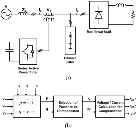
For evaluating performances of SHAPF, using the voltage reference calculation with GIPT, simulation study is performed in PSIM. Fig. 2(a) shows the arrangement of power circuit configuration which is made up of non-linear load, Passive Power Filters (PPF) bank, Series Transformer and Inverter. Typical diode rectifier is modeled as non-linear load, PPF bank is made up of 5th harmonic, 7th
harmonic, high-pass filter and 100V inverter with 1:1 series transformer is used for series injection.
(a)
i v q
i v p
× =
⋅ =
[image:3.595.307.545.176.400.2](b)
Figure 2. SHAPF (a) power circuit configuration and (b) control circuit.
Fig. 2(b) shows the block diagram of control circuit used for reference voltage generation. Three phase current and voltage are sensed and (6), (8) and (11) are evaluated for calculating reference voltage. Table I shows the system parameter values with which the simulation study is done in PSIM software.
TABLEI
COMMON SYSTEM PARAMETERS
Sr. No. Quantity Value
1 Supply Voltage 440V, 50Hz (line-line) 2 Source Impedance Rs = 0.5 Ohm, Ls = 0.1 mH
3 DC Capacitor 1000 uF
4 DC Link Voltage 100V
5 EMI Filter Lf = 1.35 mH, Cf = 50 uF
6 Tuned PPF (5th) L
5 = 12.32 mH, C5 = 32.88 uF
7 Tuned PPF (7th) L
7 = 6.29 mH, C7 = 32.88 uF
8 High Pass PPF L = 2.36 mH, C=29.88 uF, R=17.75
9 Series Transformer 1:1
10 Load Diode Rectifier supplying constant 20A DC current to load
11 Switching Frequency 20 kHz
V. RESULTS OF SIMULATION
The SHAPF model of section IV is tested for compensating 22 kVA diode rectifier for harmonic elimination. This load is drawing supply current having 21.83A fundamental, 4.2A 5th harmonic, 2.8A 7th harmonic,
1.67A 11th harmonic, 1.25A 13th harmonic, 0.82A 17th
distortion of this current is 29.46%. The performance of the system without any filter, with PPF and with SHAPF are simulated and compared.
(a)
[image:4.595.311.548.63.185.2](b)
Figure 3. Performance of system with only passive filter. Waveforms of (a) load current and (b) source current.
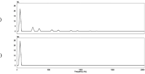
Fig. 3 shows the load current and improved supply current waveform after connecting PPF bank. Fig. 4 shows the harmonic spectrum of these current waveforms. Since the PPF bank is made up of 5th harmonic tuned filter, 7th
harmonic tuned filter and high pass filter, it is observed that 5th and 7th harmonics are completely removed and other
harmonics are attenuated. The THD of supply current which is 29.46% before compensation is reduced to 13.60% after applying PPF and individual harmonic components are also reduced.
(a)
[image:4.595.47.295.91.202.2](b)
Figure 4. Performance of system with only passive filter. Harmonic spectrums of (a) load current and (b) source current.
Fig. 5 shows the waveforms of load current, improved supply current and injected voltage waveforms when compensation is done with SHAPF. Fig. 6 shows the harmonic spectrum of load current and source current, it is observed that all the harmonics are considerably removed.
(a)
(b)
(c)
Figure 5. Performance of system with SHAPF. Waveforms of (a) load current,(b) source current and (c) series injected voltage.
As tabulated in Table II, the THD of supply current which is 29.46 % before compensation is reduced to 1.58 % after applying SHAPF. It is also observed from the value of injected voltage that the required value of compensating
voltage is small as compared to the system voltages.
(a)
(b)
Figure 6. Performance of system with SHAPF. Harmonic spectrums of (a) load current and (b) source current.
Fig. 7 shows the control circuit waveforms, which is a calculation of (11). Voltage corresponding to oscillating active power and oscillating reactive power are calculated using (6) and (8) respectively. The calculated references are compared with 20 kHz carrier wave for generating gate pulses for voltage source inverter. The injected voltage with this reference after removing high frequency switching ripples using the EMI filter are as shown in Fig. 5(c), which compensates the source current harmonics.
(a)
(b)
[image:4.595.306.549.335.462.2](c)
Figure 7. Control circuit waveforms: (a) voltage component corresponding to oscillating active power, (b) voltage component corresponding to oscillating reactive power and (c) compensation voltage.
TABLEII
PERFORMANCE UNDER DIFFERENT WORKING CONDITIONS
Sr. No. Source Current % THDi
1 Without Filter 29.46
2 With PPF 13.60
[image:4.595.47.291.361.480.2]3 With PPF plus APF 1.58
Table II shows the overall performance of the system. The THD of supply current is 29.46% without compensation, which reduces to 13.60% after connecting PPF and which further reduces to 1.58% after connecting SHAPF. The required capacity of series APF in this system is calculated to be 1.75 kVA, while compensating non-linear load of 22 kVA, which is quite small compared to a similar rating shunt APF.
VI. CONCLUSIONS
[image:4.595.48.290.580.707.2]without any form of artificial coordinate transformations. Application of this decomposition in generating reference signal for SHAPF for harmonic elimination is demonstrated. The THD of supply current is 29.46% without compensation is reduces to 1.58% after connecting SHAPF, which provesthe effectiveness of proposed method.
APPENDIX A
A.1 Inverse of a vector
Considering current vector
i
r
, its inversei
r
−1into the geometric algebra framework, can be defined as follows:2 2
† †
† 1
i
i
i
i
i
i
i
i
r
r
r
r
r
r
r
r
−=
=
=
where
i
r
is the instantaneous norm of vectori
r
(
t
)
and the fact thati
r
†≡
i
r
has been considered [16].A.2 Cross Product of Three Vectors
In the geometric algebra framework, the cross product of three vectors can be performed using expression,
c
b
a
b
c
a
c
b
a
r
×
r
×
r
=
(
r
•
r
)
r
−
(
r
•
r
)
r
A.3 Conversion of Cross Product into Matrix Multiplication
In the geometric algebra framework, the conversion of this outer product multiplication to matrix multiplication is done using following relations.
[ ]
a
b
[ ]
b
a
b
a
r
×
r
=
r
xr
=
r
Txr
and if
[ ]
( )
T T Tx
c
d
c
d
a
d
c
a
r
=
r
×
r
,
r
=
r
r
−
r
r
REFERENCES
[1] Montano, J.C., "Reviewing Concepts of Instantaneous and Average Compensations in Polyphase Systems", IEEE Transactions on Industrial Electronics, Jan. 2011, Volume: 58, Issue: 1, pp. 213 - 220. [2] Salmero´n, P.; Litra´n, S.P., “A Control Strategy for Hybrid Power
Filter to Compensate Four-Wires Three-Phase Systems”, IEEE Transactions on Power Electronics, July 2010, Volume 25, Issue 7, pp. 1923–1931.
[3] J. Tian, Q. Chen and B. Xie, “Series Hybrid Active Power Filter based on Controllable Harmonic Impedance”, IET Journal of Power Electronics, 2012, Vol. 5, Issue 1, pp. 142-148.
[4] Hirofumi Akagi, Edson Hirokazu Watanabe and Mauricio Aredes, “Instantaneous Power Theory and Applications to Power Conditioning”, IEEE Press, 2007.
[5] H. Akagi et al., “Instantaneous reactive power components comprising switching devices without energy storage components,” IEEE Trans. Ind. Application, vol. IA-20, pp. 625–631, Mar./Apr. 1984.
[6] I. Takahashi, “Analysis of instantaneous current and power using space switching functions,” in Proc. Conf. Rec. IEEE Power Eng. Syst., 1988, pp. 42–49.
[7] T. Furuhashi et al., “A study on the theory of instantaneous reactive power,” IEEE Trans. Ind. Electron., vol. 37, pp. 86–90, Feb. 1990. [8] J. L. Willems, “A new interpretation of the Akagi-Nabae power
components for nonsinusoidal three-phase situation,” IEEE Trans. Instrum. Meas., vol. 41, pp. 523–527, Aug. 1992.
[9] A. Nabae, “New definition of instantaneous active-reactive current and power based on instantaneous space vectors on polar coordinates in three-phase circuits,” IEEE Trans. Power Delivery, vol. 11, pp. 1238–1243, Nov. 1996.
[10] Hyosung Kim, Blaabjerg, F., Bak-Jensen, B. and Jaeho Choi, “Instantaneous power compensation in three-phase systems by using p-q-r theory”, IEEE Transactions on Power Electronics, Sep 2002, Volume: 17, Issue: 5, pp. 701 – 710.
[11] Fang Zheng Peng ; Ott, G.W., Jr. ; Adams, D.J., "Harmonic and reactive power compensation based on the generalized instantaneous reactive power theory for three-phase four-wire systems", IEEE Transactions on Power Electronics, Nov 1998, Volume: 13, Issue:6, pp. 1174 – 1181.
[12] Salmeron, P.; Montano, J.C., "Instantaneous power components in polyphase systems under nonsinusoidal conditions", IEE Proceedings -Science, Measurement and Technology, Mar 1996, Volume: 143, Issue: 2, pp. 151 – 155.
[13] G. Y. Li, “Definition of generalized instantaneous reactive power in dqo coordinates and its compensation,” in Proc. Chinese Soc. Elect. Eng., vol. 16, May 1996, pp. 176–179.
[14] Fang Zheng Peng ; Jih-Sheng Lai, "Generalized instantaneous reactive power theory for three-phase power systems", IEEE Transactions on Instrumentation and Measurement, Feb 1996, Volume: 45, Issue:1, pp. 293 – 297.
[15] Menti A., Zacharias T., Milias-Argitis J., "Geometric Algebra: A Powerful Tool for Representing Power Under Nonsinusoidal Conditions", IEEE Transactions on Circuits and Systems I: Regular Papers, March 2007, Volume: 54 Issue: 3, pp. 601 - 609.
[16] Herrera, R.S., Salmeron, P., Vazquez, J.R., Litran, S.P., Perez, A., “Generalised instantaneous reactive power theory in poly-phase power systems", 13th European Conference on Power Electronics and Applications, 2009. EPE '09. pp. 1 – 10.
[17] Xianzhong Dai ; Guohai Liu ; Gretsch, R., "Generalized theory of instantaneous reactive quantity for multiphase power system", IEEE Transactions on Power Delivery, July 2004, Volume : 19 , Issue:3, pp. 965 – 972.
[18] Willems, J. L., Discussion of "Generalized theory of instantaneous reactive quantity for multiphase power system" IEEE Transactions on Power Delivery, Jan. 2006, Vol. 21, pp. 541.
[19] de Leon, F. ; Cohen, J. ; Discussion of "Generalized theory of instantaneous reactive quantity for multiphase power system" IEEE Transactions on Power Delivery, Jan. 2006, Volume : 21 , Issue:1, pp. 540 – 541.
[20] Xianzhong Dai; Guohai Liu ; Closure on "Generalized theory of instantaneous reactive quantity for multiphase power system" IEEE Transactions on Power Delivery, Jan. 2006, Volume: 21, Issue:1, pp. 542 – 543.
M. A. Mulla (SM’97-2002 & M’2011-12) received the B. E. degree in electrical engineering from the S. V. National Institute of Technology, Surat, India, in 1996 and M. E. degree from the M. S. University, Vadodara, India, in 1998 and currently pursuing Ph. D. degree from SVNIT, India. He is an Associate Professor in department of electrical engineering at the S. V. National Institute of Technology, Surat, India. His research interests are power electronics in the power quality, ac-dc converters, and active power filters. He is a member of the IEEE, Indian Society of Technical Education (ISTE) and Institution of Engineers (IE), India.
R. Chudamani received her B. E. degree in electrical engineering from the S. V. National Institute of Technology, Surat, India, (formally known as REC, Surat) in 1990. She received M. Tech. degree from IIT, Delhi, India in 1997. She completed her Ph. D. on Shunt Active Power filter from IIT, Madras, India, in 2009. Since 1998 she has been with department of electrical engineering S. V. National Institute of Technology, Surat, India, where she is Assistant Professor. Her teaching activities and research interest includes power electronics and power system.