Improved Converter Design Use of SHE-PWM for
Harmonic Immunity in VSC HVDC Transmission
Gopala Narsupalli1, R.Srinivas Rao2
#1Student of M.Tech (Power Systems) and Department of EEE in Gokul Group of Institutions, Vizianagaram, #2 Assist.Prof, Department of EEE in Gokul Group of Institutions, Vizianagaram, India.
Abstract:
The idea of multilevel inverters, presented around 20 years back involves performing power change in various voltage ventures to get enhanced force quality, lower exchanging misfortunes, better electromagnetic similarity, and higher voltage capacity. The advantages are particularly clear for medium-voltage drives in modern applications and are being considered for future maritime boat impetus frameworks. A few topologies for multilevel inverters have been proposed throughout the years; the most well-known fell H-connect separated from other multilevel inverters is the ability of using distinctive dc voltages on the individual H-span cells which brings about part the force change amongst higher-voltage lower recurrence and lower-voltage higher-recurrence inverters. Control strategies in view of specific consonant end beat width tweak (SHE-PWM) systems offer the most reduced conceivable number of exchanging moves. This component likewise brings about the most reduced conceivable level of converter exchanging misfortunes. Thus, they are exceptionally alluring methods for the voltage-source-converter-(VSC) based high-voltage dc (HVDC) power transmission frameworks. The paper talks about improved regulation examples which offer controlled symphonious safety between the air conditioner and dc side. The application concentrates on the routine two-level converter when its dc-join voltage contains a blend of low recurrence symphonious segments. Reenactment and trial results are introduced to affirm the legitimacy of the proposed exchanging designs. At long last a five level multilevel converter topology is connected for this application.
Keywords: Amplitude modulation (AM), dc-ac
power conversion, harmonic control, HVDC, insulated-gate bipolar transistor (IGBT), power electronics, power transmission system, pulse-width modulation, voltage-source converter (VSC).
I. Introduction
dynamic and receptive power severally while not compensation disappointment inside of the inverters, every gadget station comprises of a VSC. For dynamic force adjustment, one amongst the gadgets works on dc voltage control and distinctive converter on dynamic force control. When dc line force is zero, the two converters, will work as free STATCOMs. Each VSC envelops at least three controllers for regulation dynamic force yields of individual VSC. It doesn't require receptive force compensator guaranteeing a ton of littler hardware size. The persistent development of power interest and steadily expanding society attention to environmental change issues specifically influence the improvement of the power framework base. The utility business faces persistent weight to change the way the power network is overseen and worked. On one hand, the assorted qualities of supply expects to expand the vitality blend and oblige more and different supportable vitality sources. Then again, there is an unmistakable need to enhance the effectiveness, unwavering quality, vitality security, and nature of supply. With the expansiveness of advantages that the savvy matrix can convey, the enhancements in innovation capacities, and the diminishment in innovation cost, putting resources into shrewd framework advances has turned into a genuine center for utilities Control procedures to repay unbalances are accounted for in the writing. Gentle lopsided characteristics brought on by uneven heaps of the air conditioner side are directed by utilizing separate control circles for the positive-and negative succession parts of the voltage as proposed in [3]. Productive control of unequal compensator streams can be accomplished by a control calculation in view of the D-STATCOM model [24]. D-STATCOM permits separate control of positive-and negative-arrangement streams and decoupled current control of the d-q outline. A propelled system taking into account direct power control under lopsided network voltage conditions has been as of late displayed for a doubly bolstered incitement generator [5]. To take the full points of interest of VSCs for HVDC power transmission frameworks, an assistant controller is added to the primary controller which is customarily actualized in the positive-succession d-q outline [6]. To adjust for unequal air conditioning side loads, the assistant controller is executed in the negative
succession d-q outline. The target of this paper is to talk about the adequacy of improved tweak in light of pre computed SHE-PWM in a two-level three-stage VSC to make the air conditioner side resistant from the variances of the dc join without the utilization of aloof segments. Be that as it may, following the VSC considered here does exclude a shut circle controller, procedures to remunerate unbalances are not tended to in this paper.
II. Power module
A power module is an electrochemical cell that changes over a source fuel into an electrical current. It produces power inside a cell through responses between a fuel and an oxidant, activated in the vicinity of an electrolyte. The reactants stream into the cell, and the response items stream out of it, while the electrolyte stays inside of it. Energy components can work constantly the length of the essential reactant and oxidant streams are kept up. Energy units are unique in relation to traditional electrochemical cell batteries in that they devour reactant from an outer source, which must be renewed a thermodynamically open framework as appeared in Fig.1. By differentiation, batteries store electrical vitality synthetically and thus speak to a thermodynamically shut framework. Numerous blends of fills and oxidants are conceivable. A hydrogen power device utilizes hydrogen as its fuel and oxygen (as a rule from air) as its oxidant. Different energizes incorporate hydrocarbons and alcohols. Different oxidants incorporate chlorine and chlorine dioxide.
II.PULSE WIDTH MODULATION (PWM)
A converter is interconnecting two electric networks to transmit electric power from one network to other, each network being coupled to a respective power generator station. The converter, having an AC side and a DC side, includes a bridge of semiconductor switches with gate turn- off capability coupled to a control system to produce a bridge voltage waveform having a fundamental Fourier component at the frequency of the electric network coupled to the AC side of the converter. The control system includes three inputs for receiving reference signals allowing controlling the frequency, the amplitude and the phase angle of the fundamental Fourier component and the alternating voltage of the network coupled to the DC side of the converter [4]. The principle characteristic of VCSHVDC transmission is its ability to independently control the reactive and real power flow at each of the AC systems to which it is connected, at the Point of Common Coupling (PCC). In constant to line commutated HVDC transmission, the polarity of the DC link voltage remains the same with the DC current being reversed to change the direction of power flow.
III. ANALYSIS OF MODULATION
A converter is interconnecting two electrical networks to transmit wattage from one network to alternative, every network being coupled to a individual power generator station. The converter, having an AC side and a DC side, includes a bridge of semiconductor switches with gate turn- off capability coupled to an control system to supply a bridge voltage wave shape having a basic Fourier component at the frequency of the electrical network coupled to the AC side of the converter. The control system includes three inputs for receiving reference signals permitting controlling the frequency the amplitude and the phase angle of the fundamental Fourier component and the alternating voltage of the network coupled to the DC side of the converter. The principle characteristic of VCS-HVDC transmission is its ability to independently control the reactive and real power flow at every of the AC systems to that it is connected, at the point of Common Coupling (PCC) in [3].In constant to line commutated HVDC transmission, the polarity of the DC link voltage
IV. ANALYSIS OF THE PWM CONVERTER & SHE-PWM
The optimized SHE-PWM technique is investigated on a two level three-phase VSC topology with IGBT technology, shown in Fig. 2. A typical periodic two level SHE-PWM waveform is shown in Fig. 3. The waveforms of the line-to-neutral voltages can be
index over a complete periodic cycle. (b) Five angles in radians.
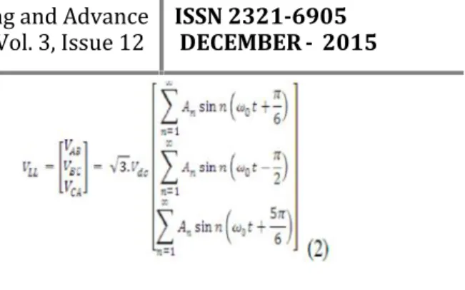
Thus, the line-to-line voltages are given by
The SHE-PWM method offers numerical solutions which are calculated through the Fourier series expansion of the waveform.
M=1 + 2
Where N+1 are the angles that require to be found. mistreatment 5 switch angles per quarter-wave in (N=4) SHE-PWM, k= 5, 7, 11, thirteen to eliminate the fifth, 7th, 11th,and thirteenth harmonics. throughout the case of a balanced load, the third and every one different harmonics that are multiples of 3 square measure off, owing to the 120 symmetry of the switch perform of the three-phase device. The even harmonics are cancelled attributable to the half-wave quarter-half-wave symmetry of the angles, being affected by
0 <α1< α2 ...<αN+1<π/2
V.FULL H-BRIDGE
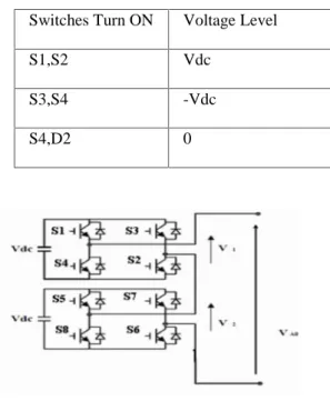
Fig.4 shows the Full H-Bridge Configuration. By using single H-Bridge we can get 3 voltage levels. The number output voltage levels of cascaded Full H-Bridge are given by 2n+1 and voltage step of each level is given by Vdc/n. Where n is number of H-bridges connected in cascaded. The switching table is given in Table 1 and 2.
Fig. 4 Full H-Bridge
expressed as follows:
When ω
0is the operating frequency of the ac, and V
dcis
the dc-link voltage.
two
Fig. 2. Typical
-
level PWM
switching waveform
with fiveangles perquarter cycle.
Table 1. Switching table for H-Bridge Switches Turn ON Voltage Level S1,S2 Vdc
S3,S4 -Vdc S4,D2 0
Table 2. Switching table for Cascaded H-Bridge Switches Turn on Voltage Level S1, S2 Vdc
S1, S2, S5, S6 2Vdc S4, D2, S8, D6 0 S3, S4 -Vdc S3, S4, S7, S8 -2Vdc
This is also termed as the optimized PWM technique. By reversing the phase voltages a few times during each half cycle, it is possible to eliminate lower order harmonics selectively. However, the higher order harmonics may increase in magnitudes, but the current harmonics are not significantly affected due to low pass filter characteristics of the AC system. The voltage reversals are affected at chosen instants such that the notches (caused by the voltage reversals) are placed symmetrically about the centre line of each half cycle.
V. ARTIFICIAL NEURAL NETWORKS
Artificial Neural Networks are being widely used in the classification problems. ANNs are massively parallel interconnected networks of simple adaptive elements and their hierarchical organizations which are intended to interact with the objective of the real world in the same way as the biological counterparts. Neural networks find wide application in parallel distributed processing and real-time environments. Neural networks have considerable advantage over expert system in terms of knowledge acquisition. An important feature of the fault diagnosis using neural networks is that they can interpolate the training patterns to give an appropriate response for cases described by neighboring or noisy input data. For a neural network, if activation and out put functions are chosen, it is completely described by the weights and node thresholds. The training process is the process of finding the weights and thresholds for the network and it is equivalent to find the unknown Input –
output relationship. Thus neural networks are appropriate and especially powerful when they are used to find such relationships that are difficult to describe explicitly. Among all the proposed neural network structure, the Feed Forward Neural Network (FFNN) is most popular one [6]. It contains an input layer, an output layer and many hidden layers.
VI. SIMULATION RESULTS
Fig.8 shows the Level shifted Carrier PWM wave form. Here two carriers each are level shifted and are compared with sine wave.
Fig.7. Output voltage
Fig.7 shows the three level output voltage waveform. Case 2
Fig.8Simulink model of the 5-level DCMLI
Fig.8 shows the Matlab/Simulink Model of five level Diode clamped multilevel converter.
Fig.9 Reference and carrier waveforms
Fig.9 shows the Level shifted Carrier PWM wave form. Here four carriers each are level shifted and are compared with sine wave.
Fig.10. Output voltage
Fig.10 shows the five level output voltage waveform of the diode clamped multilevel inverter.
Fig.11 Simulink model of the DCMLI
Fig.5 Simulink model three level DCMLI
Fig.11 shows the simulink model of the Seven level diode clamped multilevel inverter.
Fig.11 Reference and carrier waveforms
Fig.11 shows the Level shifted Carrier PWM wave form. Here four carriers each are level shifted and are compared with sine wave.
Fig.12. Output voltage
Fig.12 shows the five level output voltage waveform of the diode clamped multilevel inverter
VII. CONCLUSION
An optimized SHE-PWM technique, which offers immunity between the ac and dc side in a two-level threephase VSC, is discussed in this paper. The technique is highly significant in HVDCs due to the elimination of every low-order harmonic of the ac side produced by the link ripple voltage. The dc-link ripple repositioning technique regulates the magnitude of the fundamental component and eliminates the low-order harmonics of the ac side even when the dc bus voltage fluctuates. This is an online method which can be applied for eliminating any low-order harmonic frequency regardless of amplitude or phase shift of the ripple. There are some limitations related to the maximum modulation index available for SHEPWM angles. The repositioning technique also causes a reflection with respect to the midpoint between the fundamental component and
the first significant harmonic. There are cases where the technique is not beneficial. On the other hand, it eliminates all low-order ac-side harmonics for every dc-bus ripple voltage of frequency below the midpoint harmonic.
REFERENCES
[1] J. McDonald, “Leader or follower [The business
scene],” IEEE Powe Energy Mag., vol. 6, no. 6, pp.
18–90, Nov. 2008.
[2] N. Flourentzou, V. G. Agelidis, and G. D.
Demetriades, “VSC-based HVDC power
transmission systems: An overview,” IEEE Trans.
Power Electron., vol. 24, no. 3, pp. 592–602, Mar. 2009.
[3] A. A. Edris, S. Zelingher, L. Gyugyi, and L. J.
Kovalsky, “Squeezing more power from the grid,”
IEEE Power Eng. Rev., vol. 22, no. 6, pp. 4–6, Jun. 2002.
[4] B. K. Perkins and M. R. Iravani, “Dynamic
modeling of high power static switching circuits in the dq-frame,” IEEE Trans. Power Syst., vol. 14, no.
2, pp. 678–684, May 1999.
[5] P. Steimer, O. Apeldoorn, E. Carroll, and A.
Nagel, “IGCT technology baseline and future opportunities,” in Proc. IEEE Transmi. Distrib. Conf. Expo., Oct. 2001, vol. 2, pp. 1182–1187.
[6] V. G. Agelidis and G. Joos, “On applying graph
theory toward a unified analysis of three-phase PWM
inverter topologies,” in Proc. IEEE Power Electronics
Specialists Conf., Seattle, WA, Jun. 1993, pp. 408–
415.
[7] J. Arrillaga, Y. H. Liu, and N. RWatson, Flexible Power Transmission: The HVDC options. Hoboken, NJ: Wiley, 2007.
[8] G. Asplund, “Application of HVDC light to power system enhancement,” in Proc. IEEE Power
Eng. Soc. Winter Meeting, Singapore, Jan. 2000, vol. 4, pp. 2498–2503.
[9] P. N. Enjeti, P. D. Ziogas, and M. Ehsani,
Annu. Meet., San Diego, CA, Oct. 1989, pp. 861–
870.
[10] P. N. Enjeti and W. Shireen, “A new technique
to reject dc-link voltage ripple for inverters operating
on programmedPWM waveforms,” IEEE Trans.
Power Electron., vol. 7, no. 1, pp. 171–180, Jan. 1992.
Authors
GOPALA NARSUPALLI holds
B.Tech certificate in Electrical and Electronics Engineering from Gokul Institute of Technology And Sciences (2009-2013). She presently pursuing her M.Tech Power systems in the department of EEE, Gokul Group of Institutions, piridi Village, Bobbili Mandal, Vizianagaram, A.P., India. Affiliated to Jawaharlal Nehru Technological University, Kakinada. Approved by AICTE, NEW DELHI.