Faculty of Computer ScienceDepartment of Computer Engineering
Dissertation
GENERATION OF APPLICATION SPECIFIC HARDWARE
EXTENSIONS FOR HYBRID ARCHITECTURES
The Development of PIRANHA – A GCC Plugin for High-Level-Synthesis
Submitted to the Faculty of Computer Science in partial fulfillment of the requirements for the degree of
Doctor of Engineering (Dr.-Ing.) at the
DRESDENUNIVERSITY OFTECHNOLOGY
Author: Gerald Hempel
Date of birth: May 3, 1981 Place of birth: Zittau
First Reviewer: Prof. Dr.-Ing. Christian Hochberger Technische Universität Darmstadt Second Reviewer: Prof. Dr.-Ing. habil. Andreas Koch Technische Universität Darmstadt Expert consultant: Prof. Dr.-Ing. habil. Klaus Kabitzsch
Technische Universität Dresden
Acknowledgment
An academic thesis is never the work of a single person, therefore I want to take this opportunity to thank all people who have contributed in various ways to the successful conclusion of my dissertation.
First and foremost, I would like to express my sincere gratitude to my PhD su-pervisor Professor Dr. Christian Hochberger, who has always helped me with his large wealth of knowledge and numerous constructive discussions. I would also like to thank him for the confidence and the freedom he has provided me throughout the development of my dissertation.
I would like to acknowledge the valuable input of Professor Koch and Professor Kabitzsch, who reviewed my work as second supervisor and expert consultant, respectively. Also, I would like to recognize the work of Professor Castrillon and Professor Baader, who participated in the examination committee.
A major part of the success of this dissertation is based on contributions from student’s diploma and study theses. In particular Jan Hoyer and Michael Raitza have to be mentioned here, who implemented the foundations of my work. Also, I would like to thank Jonas Wielicki, who made an important contribution to the success of this dissertation with his work on the analysis of memory accesses. My special thanks also go to Johanna Rohde and Candy Lohse, who implemented particular synthesis optimizations. Moreover Andreas Wiese have to be men-tioned here, who helped to complete the context of my dissertation with the integration of generated hardware accelerators into the infrastructure of modern operating systems.
This acknowledgment would not be complete without mentioning my research colleagues and staff members of the Department of Computer Engineering of the TU Dresden and TU Darmstadt, who contributed to this dissertation with numerous interesting debates and ideas. My special thanks go to my friend and colleague Markus Vogt, who read many chapters of my thesis and helped me to improve it technically and linguistically. I further thank him for the maintenance and provision of the tool infrastructure that made this dissertation possible. The past few years have been stressful for my wife Susanne and my family, who always encouraged and supported me and my work at all stages. You have my special thanks.
CONTENTS
I Introduction 5
1 Introduction 6
1.1 Motivation . . . 8
1.2 Proposed Work-Flow . . . 10
1.3 Aims and Objectives . . . 11
1.4 Thesis Outline . . . 13
II Technical Background 15 2 HLS for Configurable Systems 16 2.1 Concepts of Hardware Generation for Digital Systems . . . 17
2.2 C as Input Language for HLS . . . 20
2.3 Concepts of HLS for Configurable SoCs . . . 21
2.4 HLS Projects Using Special Languages . . . 25
2.5 HLS Projects Using HDL-like Languages . . . 27
2.6 HLS Projects Based on Object-Oriented Languages . . . 28
2.7 HLS Projects Using OpenCL Based Languages . . . 30
2.8 HLS Projects Using C or C++ . . . 33 2.9 GCC PIRANHA . . . 43 3 Target Platform 48 3.1 Configurable Platforms . . . 49 3.2 Soft-Core Processors . . . 52 3.3 FPGA SoC . . . 58 4 GCC Framework 61 4.1 Compilation Flow . . . 62
2 CONTENTS
4.2 Intermediate Representation . . . 65
4.3 Optimization Passes . . . 72
4.4 GCC Plugin Interface . . . 75
III Application Acceleration 79 5 Application Analysis 80 5.1 Function Data Collection . . . 82
5.2 Loop Data Collection . . . 82
5.3 Processing the Transcript File . . . 85
5.4 Performance Estimation . . . 88
5.5 Theory of Memory Access Analysis . . . 92
5.6 Implementation of Memory-Access Analysis . . . 102
6 Application Modification 115 6.1 Modifying the GIMPLE Structure . . . 115
6.2 Accelerator Function . . . 125
6.3 Runtime Alias Analysis . . . 135
6.4 Generated Files . . . 138
6.5 OS Integration of Accelerators . . . 140
6.6 Base Address Assignment . . . 141
7 High-Level Hardware Synthesis 144 7.1 Variants of Processor Customizations . . . 146
7.2 From GIMPLE to HDL . . . 146
7.3 Generation of the State Machine . . . 149
7.4 Optimization Strategies . . . 154
8 Generated Host Processor Interface 166 8.1 Parameter Interface . . . 167
CONTENTS 3
8.2 Memory Interface . . . 173
8.3 FIFO Interface . . . 177
8.4 Accelerator Address Map . . . 180
IV Evaluation 182 9 Evaluation 183 9.1 Implementation Example . . . 183
9.2 Evaluation of Memory Access Analysis . . . 190
9.3 Benchmarks . . . 195
9.4 Influence of Register-Allocation Strategies . . . 197
9.5 Influence of HLS Optimizations . . . 201
10 Conclusion 212 10.1 Realization of Aims and Objectives . . . 213
10.2 Limitations and Future Work . . . 216
10.3 Summary . . . 218
A Examples and Code Listings 220 A.1 Alias Set Generation for Interleaved Structure Access . . . 221
A.2 GIMPLE Example . . . 222
B Platform 225 B.1 SpartanMC Instruction Set . . . 225
B.2 SpartanMC Pipeline . . . 226
C GCC Plugin 228 C.1 PIRANHA Parameters . . . 229
C.2 Heuristic Delay Times for Operations . . . 232
4 CONTENTS C.4 GIMPLE Statements . . . 233 C.5 Tree Types . . . 234 C.6 Operations . . . 236 D OS Integration 237 E Evaluation Results 247 E.1 Comparison of Register-Allocation Strategies . . . 247
E.2 State Machine Evaluation . . . 249
E.3 Performance Evaluation . . . 253
E.4 Performance Estimation . . . 254
E.5 Data Transfer Evaluation . . . 255
List of Figures 256
List of Tables 260
Part I
Introduction
1
INTRODUCTION
The ongoing digitalization of our everyday life entails several challenges for fu-ture computing systems. Particularly in the area of embedded systems there has been an increasing need for better computing performance along with im-proved energy efficiency. For a long time, this was achieved by downsizing the underlying semiconductor technology and increasing the clock frequency of cir-cuits. Both approaches have recurrently been pushing the manufacturing pro-cess of such circuits to its technological limits. In recent years, the rise of circuit frequencies has stagnated due to the physical limits of current semiconductor technology. Since increasing the clock frequency is no longer an easy way to achieve performance improvements, the design paradigm has changed to real parallel systems implementing multiple-processor cores on a single chip. This has revealed new bottlenecks such as the communication and synchronization over-head of programs. Even worse, designers and tool developers are now forced to rethink the software design process as performance improvements are no longer achievable by simply executing the old program on the new architecture.
Nonetheless, the introduction of multi-core systems has been a success for the consumer market as well as for scientific applications. Since then, programs are being divided into different tasks running on dedicated processor cores. This helps with arising performance problems but also increases the energy consump-tion of the whole system.
General-purpose processors are able to solve nearly all kinds of computational problems, this often comes at the price of poor power efficiency. Therefore, em-bedded systems with strict energy constraints or an inefficient main processor often resort to additional hardware units that provide the best energy efficiency for a specific task. The next stage of evolution for such systems has been the customization of hardware to the particular needs of the program. This develop-ment has been strongly supported by the availability of low-cost reconfigurable devices. This introduces several new challenges for system designers. Recon-figurable systems are no longer based on static hardware. Thus, new design methodologies are required in order to unify the software and hardware design process.
8 CHAPTER 1. INTRODUCTION
This thesis presents a tool-flow that helps system designers to benefit from application-specific hardware accelerators without relying on special hardware knowledge.
1.1
Motivation
In recent decades, embedded systems have become a ubiquitous factor in nearly all aspects of our lives. The classical definition describes an embedded system as part of a larger technical system that is designed for one specific task [92, p. 1]. This definition is still true for many embedded systems that work within products designed for a single purpose for instance, the bending light control of a car. Typically, they are designed for one task or a fixed range of functionalities that do not change over the complete life cycle of the product.
Today’s challenges emerge from the idea of closely meshed applications and ser-vice architectures often referred to as the Internet of Things, and will undoubt-edly increase the need for embedded systems. However, the classical definition for such systems needs refining. On the one hand, the large number of different tasks and devices impedes the successful economical design of tailored systems for single tasks. On the other hand, especially small devices still require special hardware in order to meet real-time conditions or energy constraints. Moreover, tightly coupled devices cannot operate in a closed environment; they have to stay prepared for changes in the surrounding systems or even for deliberate attacks. It is not always desirable to replace all of them when security, communication or coding standards have changed. For this reason, the need for more flexible systems that can adapt their software and hardware will increase.
These challenges have partly been met by the design of system on chip (SoC) architectures. An SoC combines all functionalities required by the system on a single chip. A popular example is the Qualcomm Snapdragon architecture [111] used in current smartphones. It contains nearly all system components on a sin-gle die. These include, among others, a general-purpose processor, an H.265 MPEG decoder and a graphics processing unit (GPU). This allows its usage in a multi-purpose device where the actual requirements are specified by the end user. It saves the system designer from the tedious and error-prone process of
1.1. MOTIVATION 9
designing a system with individual components. This kind of flexibility, however, is not sufficient for some applications, as it does not allow for a change in the behavior of the hardware components, if necessary. For instance, the current H.265 video decoder implemented on the Snapdragon will be nearly useless as soon as the new standard H.266 is fully established. Additionally, for many com-panies, it is not economically feasible to design and manufacture such a complex SoC architecture1.
A promising alternative to raise the degree of hardware flexibility is the use of field programmable gate arrays (FPGA). These enable a change in the hardware even in a shipped system and involve a reasonable price for custom designs. In comparison to ASIC design, they reduce development efforts and time-to-market. At present, FPGAs are already the platform of choice for many embed-ded projects. However, classical FPGAs cannot handle the growing complexity of todays applications, as pure hardware layouts lack the flexibility and expressive-ness of software designs. Hence, it is hardly surprising that, according to a Men-tor Graphics functional verification study [107], more than 56% of FPGA designs contain at least one general-purpose processor. Combining both, processors and reconfigurable logic, has the potential to enable the design of complex software in perfect interaction with custom hardware. Besides the gained flexibility, this also has the potential to improve the platform’s energy efficiency as well as the execution speed of the software.
Despite that, the price for this benefit is a complex and time-consuming design-flow that forces the designer to implement the system on a degree of abstraction that requires comprehensive knowledge of the underlying hardware. On these grounds, many developers flinch from using reconfigurable logic.
Consequently, today’s challenge is the seamless and transparent integration of the hardware design-flow into software development.
1The mask costs of an application-specific integrated circuit (ASIC) based on 20 nm technology amount to around five
10 CHAPTER 1. INTRODUCTION
1.2
Proposed Work-Flow
In order to bring the hardware design-flow as close as possible to typical soft-ware design-flows, the integration of the hardsoft-ware generation into a full-featured software compiler is a natural choice. The chosen compiler environment for this thesis was the Gnu Compiler Collection (GCC) framework. This compiler is widely used for industrial applications, provides a rich set of optimization strategies, and supports several embedded platforms. Moreover, it is an open source project that allows modifications and custom extensions by default.
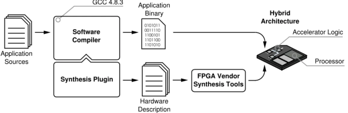
The basic idea of this thesis is to integrate hardware generation into the GCC compilation process in order to make it transparent to the developer. There should be no major differences in comparison to compiling a regular software project. Figure 1.1 outlines the proposed work-flow. The input for the compilation is a plain C application. The following software compilation is carried out by the GCC while the hardware generation is handled by an additional GCC-plugin. The integration of the plugin is implemented in such a way that the hardware genera-tion benefits from most optimizagenera-tions provided by the GCC software compilagenera-tion flow. Finally, the result is divided into two parts: the application binary and sev-eral hardware description files. The latter require further processing by platform-specific tools in order to generate a bit-file for the programmable logic. The proposed target machine consists of a fixed part containing a general-purpose processor and a configurable part containing the generated logic. The generated logic acts as a special peripheral unit executing suitable hotspots of the software application. Such peripheral units will be later referred to asaccelerators.
0011110 1100101 1101100 1101010 0101011 Application Sources FPGA Vendor Synthesis Tools Hardware Description Accelerator Logic Synthesis Plugin Hybrid Architecture GCC 4.8.3 Application Binary Software Compiler
1.3. AIMS AND OBJECTIVES 11
The general-purpose processor can be implemented in two ways. First, it is pos-sible to use a classical FPGA programmed with a hardware design that complies with the specification of a processor. This is also called a soft-core processor. Although the soft-core is quasi-static from the perspective of accelerator gen-eration, the complete design is still customizable. This allows the adaptation of critical system components for instance, the peripheral interface to fit seamlessly with the generated accelerators.
Second, it is possible to use special platforms that already contain a processor core in silicon in combination with programmable logic. Such ASIC-like system components are called hard-cores. Even though such processor platforms are less flexible, they provide the typical advantages of highly integrated circuit de-signs for example excellent power efficiency and a high clock frequency. The combination of hard processor cores, typically with a rich set of standard periph-erals, and an FPGA fabric is also referred to as FPGA-SoC.
In this thesis, the term ”hybrid architecture“ comprises FPGA-SoCs as well as FPGAs containing soft-core processors.
1.3
Aims and Objectives
At present, the standard way of creating hardware accelerators is to develop them manually. This process is time-consuming and error-prone.
The goal of this thesis is to implement a tool-flow that helps the developer to create hardware accelerators automatically, starting from a high-level software description. The tool-flow should provide the following features:
• The possibility to handle plain C as input language. The target C code should require neither refinements nor special annotations. This condition lowers the entry barrier for non-hardware developers considerably and further en-ables support for legacy application code.
• Seamless integration into a standard software compiler, namely the GCC.
This should allow developers to take advantage of optimizations in the soft-ware compilation flow for the generation of hardsoft-ware. Reuse of the GCC front-end should further reduce the effort for syntax analysis and code parsing.
12 CHAPTER 1. INTRODUCTION
Furthermore, the usage of the GCC helps to provide a transparent tool-flow for most software developers.
• Automatic selection of promising code sequences. It should not be
pos-sible or necessary to map the whole application code to hardware. Code sequences containing promising application hotspots should be extracted automatically. There is no need for manual code annotations or special lan-guage extensions in order to select parts of the application.
• Automatic patching of the software in order to call generated accelerators.
The invocation should remain completely transparent to the user. It should also include an optional fall-back to software execution.
• Automatic generation of a memory and a host-processor interface.
• Portability to other processor architectures. This means a modular interface concept and a platform-agnostic generation process for hardware accelera-tors are required.
The generation of hardware accelerators from unmodified C code poses many challenges for an automatic tool-flow approach. Most likely, some of these chal-lenges can never be overcome due to the lack of hardware-specific information within the C language definition. However, the idea of this work is to consider only those code sequences that provide sufficient information for a good hard-ware generation. This comprises two assumptions.
First, there must be enough code sections in legacy C code that comply with
the requirements for hardware generation. Second, the static code analysis
during program compilation provides sufficient information for accelerator gen-eration. Note that these two conditions are not completely independent of each other. A good static code analysis allows identifying more suitable code sections, whereas a suitable initial application code reduces the effort for the required code analysis and hardware generation. This leads to one key question: Which im-provements in the application performance can be achieved with a static code analysis for a given application and target platform?
1.4. THESIS OUTLINE 13
1.4
Thesis Outline
This thesis is divided into four parts. After Part I introducing the work, Part II which encompasses Chapters 2 to 4, gives an overview of the technical back-ground. Part III, comprising Chapters 5 to 8, describes substantial parts of the presented tool-flow and gives detailed information about its implementation. Fi-nally, the results of this thesis are evaluated and summarized in Part IV.
Part II starts with the second chapter, which emphasizes the challenges and op-portunities for system development using high-level-synthesis (HLS). Hence, the impact of different input languages for HLS is discussed and an overview of ex-isting HLS approaches for configurable platforms are given. Finally, the HLS com-piler plugin that forms the basis of this thesis is introduced.
The first part of Chapter 2 discusses possible hardware architectures for the pro-posed work-flow. The second part will introduce the hardware platforms that were actually used in the context of this work. This includes an explanation of the features and architecture of the soft-core processor SpartanMC and the com-mercial Xilinx Zynq-7000 platform.
Chapter 4 gives an overview on the GCC framework. The GCC is the underlying compiler for the proposed HLS plugin. Consequently, most of the used structures and programming paradigms are tightly coupled to the software architecture of the GCC. This chapter will give an overview of the compilation flow itself, as well as on the intermediate representation and the optimization used by the compiler. Finally, the plugin interface of the used GCC version is introduced.
Part III, comprising the following four chapters, describes the different steps that are necessary to generate hardware accelerators for the given target platforms. Chapter 5 explains of the application analysis to determine parts of the applica-tion that are suitable for acceleraapplica-tion. The selecapplica-tion of applicaapplica-tion hotspots is explained as well as different methods to determine the presumable efficiency of the extracted accelerator at compile time.
After the selection of hotspots, the application must be modified in order to call the generated hardware accelerators. This problem is tackled in Chapter 6. First, techniques for modifying the intermediate representation are explained. After-wards, a description of the integration of accelerators in the software application
14 CHAPTER 1. INTRODUCTION
with respect to different target architectures is given. The chapter closes by intro-ducing methods for the integration of generated accelerators into a full-featured operating system.
Chapter 7 presents the algorithms required for the high-level-synthesis of accel-erators at compile time. It describes the transformation of an application hotspot from the internal compiler representation into the hardware description of a finite-state machine (FSM).
Chapter 8 presents three ways of interfacing with the respective host processor of the given target platforms. The interfaces will be discussed in the context of the host processor architecture and the underlying software environment.
Finally, Part IV concludes this thesis. The presented approaches are evaluated in Chapter 9, starting with a case study to show the operability of the presented work-flow. Additionally, the effectiveness of the application analysis is investi-gated using a considerable set of benchmark applications. Finally, the overall performance is evaluated for both target architectures.
Chapter 10 discusses the achievements of the presented thesis. The conclusion also addresses limitations of the current approach and gives recommendations for future improvements.
Part II
Technical Background
2
HLS FOR CONFIGURABLE SYSTEMS
2.1
Concepts of Hardware Generation for Digital Systems
In this thesis, the generation of hardware for digital systems means the mapping of an abstract algorithmic problem to the specific physical structure of a circuit. In the early years of circuit design this was done by utilizing elements of the target platform typically on the granularity of logic gates or even single transistors. This approach is no longer feasible for todays chip technology. In order to raise the level of abstraction, nowadays designers strive for behavioral descriptions of the desired algorithm without any reference to the structures of the underlying target platform.
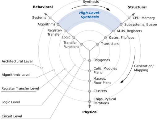
A well-known abstraction model for circuit design is the Y-chart shown in Fig-ure 2.1, which was introduced by Gajski et al. [98] and refined by Walker et al. [118]. This chart allows visualizing design views as well as design hierarchies. The char-acteristic Y-form arises from three radial axes showing three different design do-mains: behavioral description,logical structureandphysical structure.
Algorithms Register-Transfer Systems Logic Transfer Functions Subsystems, Busses ALUs, Registers CPU, Memory Gates, Flipf Transistors Polygones Cells, Modules Plans Macros, Floor Plans Clusters Chips, Pysical Partitions Behavioral Structural Physical Circuit Level Logic Level
Register Transfer Level Algorithmic Level Architectural Level Generation/ Mapping Synthesis High-Level-Synthesis lops
18 CHAPTER 2. HLS FOR CONFIGURABLE SYSTEMS
Five concentric circles represent the hierarchical levels of abstraction within the design process. The abstraction level increases from the innermost to the outer-most circle. Within this chart a system can be specified for all three domains by using the following abstraction levels:
Architectural Level Abstract behavioral specification of system requirements and its basic concepts.
Algorithmic Level Functional description of subsystems and their interaction.
Register-Transfer Level Detailed description of data-flows and transformations on register level.
Logic Level Specification of the design on the level of logic gates and flip flops.
Circuit Level Specification of the system on the level of basic physical elements. This level can be used to implement the actual hardware device.
The process of circuit design is modeled by specializing the problem description by moving from the outermost abstraction level to the center of the chart. In reality, this process often requires transition between domains. The transition from the behavioral to the structural domain is called synthesis.
2.1.1 High-level-Synthesis
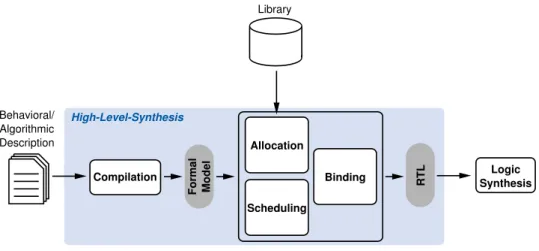
The synthesis steps performing the specialization from algorithmic level to reg-ister-transfer level are of particular interest within this thesis. This part is called high-level-synthesis. According to [115], the main task of HLS is the decomposi-tion of a given behavioral or algorithmic descripdecomposi-tion into a datapath and control-flow. The description can be either a program written in a high-level language or an abstract behavioral model, as provided by several tools e.g. MatLab [54, 30] and LabView [23]. An abstract work-flow is given in Figure 2.2 and consists of the following four tasks:
Compilation Translating the behavioral/algorithmic description into a formal mo-del, for instance, a control data-flow graph (CDFG).
Allocation Identifying the quantity and requirements of hardware resources for the operations of the algorithm. In addition to functional units like arithmetic
2.1. CONCEPTS OF HARDWARE GENERATION FOR DIGITAL SYSTEMS 19 Behavioral/ Algorithmic Description Formal Model Compilation RTL Allocation Scheduling
Binding SynthesisLogic
High-Level-Synthesis
Library
Figure 2.2: High-Level-Synthesis design steps
logic units (ALUs), this includes registers, memories, and communication resources. The allocation can be supported by libraries providing optimized functional units.
Scheduling Assigning all operations to a specific time interval with respect to given resource and timing constraints.
Binding Assigning all variables/data to corresponding memory resources (e.g. registers). Furthermore, operations are assigned to functional units, and data transfers to communication resources.
The usual result of an HLS tool is a problem description on register-transfer level, which is further synthesized to gate level by the logic synthesis. Typically, the register-transfer level is expressed in hardware description language (HDL). While traditional HDLs, like VHDL [85] and Verilog [84], are good at describing detailed hardware-properties such as timing behavior, they are generally cumber-some in expressing higher-level abstractions. Hence, HDLs may not be the first choice to meet future productivity requirements for large and complex hardware designs. Furthermore, they are hard to use for most software programmers. Thus, it is worthwhile to focus on HLS tools that allow algorithmic descriptions using a much more abstract input language.
20 CHAPTER 2. HLS FOR CONFIGURABLE SYSTEMS
2.2
C as Input Language for HLS
There is an ongoing discussion in the research community about suitable input languages for HLS. First attempts extended established HDLs like Verilog and VHDL with behavioral language features. The resulting behavioral-HDLs [112, 94] were processed by the first commercial HLS tools, e.g. the Synopsys Behavioral Compiler [38].
Although those languages enable the desired higher level of abstraction, the ac-ceptance from the user community is rather low. Consequently, the next step for HLS tools was the usage of a widely used input language. The obvious choice was C, which is accepted and frequently used for industrial and research projects. Typical HDLs define a set of statements simultaneously taking effect after a de-fined trigger condition is met. Naturally, this is useful for hardware development, as it allows the description of parallel structures as well as strict timing behaviour. However, C is a procedural language optimized for serial execution on a single general-purpose processor. For usage in HLS, C has several stumbling blocks:
• The width of operators and operations is fixed and only defined by the used
data type. This prevents the synthesis tool from generating registers and buses of arbitrary width.
• Some C constructs are not suitable for synthesis, especially code working on an unpredictable amount of resources, e.g. dynamic memory management or recursion.
• The lack of information about timing and input/output (IO) behavior requires special treatment of such code sections.
• Instruction-level parallelism (ILP) is not directly exposed. Typically, this is the first source of speedup for custom hardware; thus, it is mandatory to exploit such parallel operations. The second form of parallelism is thread-level par-allelism (TLP). Naturally, threads are directly utilized by special library calls, which make them easy to find for synthesis tools. But in most cases the granularity of whole threads is not suitable for direct automatic hardware generation, as they usually contain long and complex code fragments. Nev-ertheless, TLP may be useful for hardware acceleration as it provides the
2.3. CONCEPTS OF HLS FOR CONFIGURABLE SOCS 21
potential for real parallel code execution between processor and hardware accelerators.
• Arbitrary pointer access is a problem for most HLS tools. It prevents synthe-sis tools from determining a predictable pattern for memory accesses. This aggravates the typical memory bottleneck for hardware accelerators.
• One of the major challenges for C-based HLS is the lack of information about the aliasing of memory accesses (cf. Section 5.5). Aliasing is not explicitly exposed or prevented in C code as it is nearly irrelevant for serial execution. Unfortunately, it prevents all attempts of data prefetching or parallelization of memory accesses in HLS. Thus, aliasing is a major issue for HLS that requires special attention.
Some of these issues, e.g. the unknown operator width, result in slightly sub-optimal hardware. For this reason, they are ignored by most synthesis tools. Others, like recursion and dynamic memory management, are often suppressed by the design-rules of the HLS tool.
2.3
Concepts of HLS for Configurable SoCs
The following sections will give an impression of tool-flows that provide a unique methodology or have a major impact on the field of automatic HLS research. The overview is given with respect to the main objectives of this thesis. At the end of each survey a brief summary categorizes the approach by its input language, the proposed target architecture, its level of automation, and its design objective. The design objective describes the ability of the proposed tool-flow to generate a consistent SoC containing both custom hardware and software parts. Therefore, a tool-flow requires the capability for an automated hardware/software co-design. In this thesis, three varieties of design objectives have been distinguished.
Single IP1 Mapping: Tool-flows that are based on this approach are special-ized to map the whole application or a well defined part of the application to a custom hardware design. It requires additional effort to integrate the resulting hardware into the surrounding system. Typically, such approaches 1IP stands forIntellectualProperty which denotes a reusable component of a circuit design
22 CHAPTER 2. HLS FOR CONFIGURABLE SYSTEMS
provide generic interface logic that must be adapted to the given hardware. The choice of suitable application hotspots is delegated to the developer. Both tasks require profound knowledge of the hardware platform.
Software Back-Delegation: The concept of software back-delegation is much more convenient for the developer, as it aims to generate complete SoCs with software and hardware parts. Besides the configurable platform, sys-tems using this concept provide a general-purpose processor, which exe-cutes the program sections that failed to meet performance requirements or contain unsynthesizable program statements. Potentially required inter-faces are generated automatically with respect to an underlying target plat-form. Having the opportunity to switch back to software enlarges the po-tential code base for accelerators but also introduces additional overhead for data transfers.
Hybrid Architecture: Similar to software back-delegation, this concept aims at platforms consisting of a general-purpose processor and a configurable part. The application basically runs on the software processor while only fully syn-thesizable hotspots are mapped to customized hardware units. In contrast to software back-delegation the resulting hardware accelerators might be smaller and the overhead of data-transfers, often a crucial point when aim-ing at speedups, can be minimized.
All tool-flows that were examined within this thesis are intended for the offline synthesis of hardware units. Besides these approaches, there are several other projects taking advantage of online hardware synthesis. Typically, they are based on coarse-grain reconfigurable architectures [10]. These architectures require very little configuration data and allow fast reconfiguration during application runtime. Though, the used algorithms and mechanisms are often similar, such projects [56, 49, 26] represent another research field and will not be discussed in this thesis.
2.3.1 Taxonomy of Existing HLS Tool-Flows
In the last 25 years various HLS work-flows with scientific and industrial
2.3. CONCEPTS OF HLS FOR CONFIGURABLE SOCS 23
achieve their goals, even though the main objective namely, raising the level of abstraction for hardware development is identical. However, many work-flows arose from individual challenges. As a result, they provide a large variety of qual-ities that are not relevant in context of this thesis. Hence, several properties are not addressed in the following survey.
The used taxonomy considers five major attributes to distinguish the presented HLS approach from past and recent HLS work-flows:
Input Language: The language or behavioral description that is required to hand the algorithmic problem to the HLS tool. It is either an established high-level programming language or a special language typically adapting features from other languages. The latter is sometimes achieved by modifying a given lan-guage. In such cases the following survey gives a hint to the used enhance-ments or constraints.
Concept: The concept characterizes the scope covered by the proposed work-flow. Some work-flows are used to design a complete system containing both software and hardware parts while others are limited to pure hardware
design. The distinguished design concepts Single IP Mapping, Software
Back-Delegation andHybrid Architecturewere described in Section 2.3.
Flexibility: The flexibility describes the capability of the approach to address problems from different application domains. Typically, this attribute is strong-ly influenced by the static part2 of the given target platform or the input
lan-guage. Due to their respective architecture templates some approaches can not support certain interface types (e.g. streaming) or the language restricts the usage of language features (e.g. arbitrary pointers). Obviously, such constraints limit the flexibility.
Almost a domain-specific language or architecture.
Usable for HW-design only or introduces major limitations. HLS tool requires minor refining of programs.
All features of a high-level language are supported.
2The part of the hardware that is invariant to application-specific hardware customizations, e.g. buses, host processor
24 CHAPTER 2. HLS FOR CONFIGURABLE SYSTEMS
HW/SW Co-Design: The hardware (HW)/software (SW) co-design attribute de-scribes the degree of automation provided by the tool to support the user with the selection of hardware accelerators. Obviously, this feature is not
required for approaches that are based on theSingle IP Mappingconcept.
HW/SW co-design not in scope of the tool. HLS tool allows manual selection of accelerators.
HLS tool supports the user by suggesting suitable code section. Selection of accelerators is completely transparent to the user.
InterfaceThe interface attribute specifies the ability of the tool to automatically choose different interface types.
Interfaces must be implemented manually. The tool provides a library of interfaces.
Interfaces were suggested after memory analysis.
2.4. HLS PROJECTS USING SPECIAL LANGUAGES 25
2.4
HLS Projects Using Special Languages
Due to the known issues with C for HLS, several research groups tried to find other ways to raise the productivity of hardware design. Some introduced com-pletely new languages that circumvent arising problems with the existing ones. Others tried to adapt major languages with domain-specific constructs that po-tentially fit better with the needs of hardware development than C.
2.4.1 HLS Projects Based on Functional Languages
The idea of using a functional language to describe hardware is quite popular in academic HLS-projects [55, 41, 12]. It must be admitted that functional languages have some points in common with HDLs. For example, the model that describes combinatorial logic is a mathematic equation that is easy to decompose by using functional languages. Another important point is, that the order in which a func-tional language is evaluated does not matter as long as data dependencies are respected. For that reason, it is easy to exploit parallelism from such languages. Haskell is a widely used functional language and the basis for several HLS-projects [12, 44, 9]. All these projects aim at a new way of describing hardware in order to supplement or even replace classical HDLs as input language. The principle of operation for those languages is to provide a library of Haskell functions and types. They form the language primitives of a domain specific language tailored to the hardware description.
26 CHAPTER 2. HLS FOR CONFIGURABLE SYSTEMS
2.4.2 CλaSH
A prominent example for the use of a functional language for hardware
devel-opment is CλaSH [9], which stands for CAES (Computer Architecture for
Em-bedded Systems) Language for Synchron-ous Hardware. The CλaSH-compiler
allows translating Haskell modules into VHDL. The modules have to be written
in a very concise way using a hardware-oriented subset of Haskell. Thus, CλaSH
tries to combine the best of two worlds. On the one hand, it provides the flexibil-ity of a functional language comprising a template language for introducing new HDL primitives, it also provides the possibility to define higher-order functions
for procedural hardware generation. On the other hand, CλaSH provides the
low-level expressiveness of typical HDLs by enabling the description of bit-accurate hardware structures.
Hardware designs written in CλaSH are comparable to hand-optimized VHDL
de-signs in terms of size and performance. The use of Haskell code allow a concise description of complex functions. However, pure functional languages are not widely accepted in the industry even though they are elegant. This is caused by the fact that such approaches typically provide ways for effective implementa-tions of simple transformational algorithms but lack expressiveness or productiv-ity for complex stateful algorithms or whole system descriptions.
CλaSH Summary
Input Language: Haskell with libraries
Design Concept: Specialized IP core
Flexibility: Arbitrary hardware-design
HW/SW CO-Design: No direct support for HW/SW co-design
2.5. HLS PROJECTS USING HDL-LIKE LANGUAGES 27
2.5
HLS Projects Using HDL-like Languages
Some approaches refine the design flow and structure of current HDL-languages. They borrow features from other programming languages and typically create a new one. Examples of this approach are SystemVerilog [2] and Bluespec Sys-temVerilog [46].
2.5.1 Bluespec SystemVerilog
While SystemVerilog extends Verilog with new language features, Bluespec Sys-temVerilog uses a fundamentally different approach. It reuses elements of func-tional languages, which thereby find their way into commercial tools. Bluespec Inc. was founded as a company in 2003 to market HLS tools based on the Blue-spec System Verilog HLS language. The BlueBlue-spec language is strongly inspired by Haskell but also has adapted features and syntax that resembles Verilog. On the one hand, it uses functional rules similar to Haskell and provides a strong type system that allows language features like polymorphism. On the other hand, it provides timing and control-flow structures similar to Verilog. An additional feature of Bluespec System Verilog is the special syntax for atomic transactions. It allows to describe complex control structures in an elegant and compact way, and ensures a precise and well-defined concept of chronological sequences. In this paradigm, hardware is described as a data-flow network consisting of atomic rules. State changes happen simultaneously when rules are fired. Parallelism is achieved through concurrent execution of non-conflicting rules.
Bluespec Sytem Verilog Summary
Input Language: HDL-inspired Language
Design Concept: Specialized IP core
Flexibility: Arbitrary hardware-design
HW/SW CO-Design: No direct support for HW/SW co-design
28 CHAPTER 2. HLS FOR CONFIGURABLE SYSTEMS
2.6
HLS Projects Based on Object-Oriented Languages
There are several projects that translate high-level languages (other than C) into hardware. Examples are Kiwi [57] (based on C#) and Lime [8] (based on Java). In order to enable hardware-specific features, such languages typically provide a customized API to the developers. It allows describing a whole system in a hardware friendly but still object-oriented manner.
2.6.1 Liquid Metal and Lime
Besides the object-oriented features of Java, Lime programs expose parallelism and enable bit-level analysis. Programs written in Lime can use a restricted form of Javaenumtypes that guarantee their immutability. Together with the qualifier
local, Lime allows the isolation of computation and eases the mapping of code
sections to different (hardware) units. Moreover, Lime provides keywords for abstract parallelism (task), streaming (=>), and data parallel constructs like map (@) and reduce (!).
Using the Lime language together with the Liquid Metal project [33] enables programmers to compile the same code into either pure software binaries or software/hardware co-designs. The proposed work-flow is shown in Figure 2.3.
Lime
Program SIR CompilerSIR SIR
(opt imized) Crucible Limeade Compiler SIR Back-End Bytecode Back-End FPGA Vendor Tools PPC CPU FPGA Annot ated Byte code LMRT Verilog FPGA Bitfile
Xilinx Virtex 4
IBM PowerPC 405
2.6. HLS PROJECTS BASED ON OBJECT-ORIENTED LANGUAGES 29
As Lime is basically Java code with some additional features, it can be flawlessly translated into Bytecode. In a first step, the Limeade compiler (cf. Figure 2.3) checks for compliance with the Lime coding-rules. These rules are required for hardware compilation in order to avoid problematic program structures for in-stance, object aliasing. Suitable parts of the program will be translated into a synchronous dataflow model that will be further optimized by the synchronous intermediate representation (SIR) compiler. Finally, the mapping into HDL is
car-ried out by the Crucible compiler. The resulting code runs on an FPGA-SoC3.
Depending on the specification in the Lime code, a tailored interface to transfer data between the hardware and software part of the application is generated. It is utilized by the Liquid Metal runtime (LMRT) in the resulting system. Conse-quently, the communication with the hardware accelerator is transparent for the system designer as long as the used communication pattern is implemented in the LMRT.
Liquid Metal with Lime Summary
Input Language: Java with extensions
Design Concept: Heterogeneous architecture (CPU,GPU,FPGA)
Flexibility: Plain Java but requires special keywords and
cod-ing rules for hardware parts
HW/SW CO-Design: Lime-conform code sections determine future
hardware parts
Interface: Runtime environment using various interfaces
30 CHAPTER 2. HLS FOR CONFIGURABLE SYSTEMS
2.7
HLS Projects Using OpenCL Based Languages
Open Computing Language (OpenCL) is an open industry standard for program-ming heterogeneous and parallel computing platforms such as GPUs, DSPs, and FPGAs. Although OpenCL is largely used for GPU programming, the design paradigm is similar to all HLS design flows targeting streaming problems for FP-GAs namely HLS projects based on Impulse-C [61] or CUDA [29, 48].
2.7.1 Altera OpenCL
One of the most popular examples for a commercial tool-flow using OpenCL [35, 22, 21] was created by Altera. Programs using this language demand a hierarchi-cal memory layout similar to the hardware layout of GPUs. Although the program is mapped to an FPGA, many parts of the architecture are generated from fixed modules. Altera OpenCL relies on the template FPGA architecture sketched in Figure 2.4. It consists of modules that have been manually optimized for the underlying reconfigurable architecture. In particular, performance-critical parts, for instance, the external memory interface benefit from this strategy. The only custom-generated parts of the design are the kernel pipelines, which contain the datapath and the control unit of the computational kernels.
External Memory Controller and PHY External Memory Controller and PHY PCIe
FPGA
Global Memory Interconnect
Memory Memory Memory Memory Memory Memory Local Memory Interconnect Local Memory Interconnect Local Memory Interconnect DDRx X86 External Processor Kernel Pipeline Kernel Pipeline Kernel Pipeline DDRx
2.7. HLS PROJECTS USING OPENCL BASED LANGUAGES 31
Virtually, the proposed work-flow (Figure 2.5) starts with two separate programs. First, is the classical C/C++ part that is running on the host machine (mostly an x86 processor). It is responsible for queuing and transferring data to the OpenCL computing device. Second, is the OpenCL-C part that is running on the pro-grammable hardware. Only the second part requires the special HLS tool-flow that is provided by the Altera OpenCL compiler. Hence, the software/hardware partitioning is inherent to the code structure containing dedicated parts for the host processor and the configurable hardware. In order to introduce existing hardware kernels to the host compiler, the auto-discovery module is used. It provides information about the kernel itself and its interfaces.
host.c kernel.cl Verilog ACL Host Library 0011110 1100101 1101100 1101010 0101011 Host Binary C Compiler C-Language Front-End Live-Value
Analysis GenerationCDFG Scheduling GeneratorRTL
System Integration (QSYS/Quartus) Auto-Discovery Module Kernel Compiler
Figure 2.5: Altera OpenCL tool-flow [22]
As described in [7], the OpenCL code itself is a subset of the ISO C99 standard with additional support for parallelism. On the one hand, it provides extensions for special data types, e.g. vectors or 2D/3D work items, on the other hand it prohibits function-pointers, recursion and dynamic arrays. A special feature of OpenCL is the hierarchical memory structure that is reflected by the C code
through special key words for variable declaration (e.g. __host, __global,
__local). Together with the special data types, this enables data locality and
compensates for the lack of information about memory accesses.
32 CHAPTER 2. HLS FOR CONFIGURABLE SYSTEMS
several case studies. If used properly, it leads to impressive speedups on
re-configurable hardware. It even outperforms comparable implementations on
GPUs [53] in terms of speedup and/or energy consumption. Due to the flexibility provided by the reconfigurable architecture it is possible to fit problems accu-rately to the provided memories, which makes it easy to beat a GPU architecture with a fixed memory size.
In summary, the Altera OpenCL tool-flow provides good speedups connected with a well-estab-lished programming paradigm. However, this comes at the cost of a strict program structure targeting a more or less static hardware architecture. Currently, the proposed architecture is not designed for usage with SoCs.
Altera OpenCL Summary
Input Language: C/C++ and OpenCL extensions
Design Concept: Fixed architecture template for FPGA
Flexibility: Tailored for streaming applications → adapting
new algorithms requires substantial refinement
HW/SW CO-Design: Separate development of hardware and software
(using seperate files for each part)
Interface: FPGA connected with general-purpose
2.8. HLS PROJECTS USING C OR C++ 33
2.8
HLS Projects Using C or C++
In order to overcome the issues with C as input language for HLS (cf. Section 2.2), many approaches revisit the usage of C by using a subset of the language or by modifying the language to meet the requirements of hardware generation.
2.8.1 SystemC
The basic idea of SystemC [4] is the usage of C++ as a unified language for hardware and software. As full-featured C++ would be too complex for hardware generation, SystemC provides a C++ class library tailored to the special needs of hardware design. Developers either use parts of the library that are suitable for hardware-mapping or implement their code using the complete set of C++ features. The latter implies that the code has to run in software. The resulting system can be regarded as hardware/software co-design containing parts of the application designed for software or simulation purposes and containing parts for hardware generation. #include "systemc.h" #define WIDTH 4 SC_MODULE(adder) { sc_in<sc_uint<WIDTH> > a, b; sc_out<sc_uint<WIDTH> > sum; void do_add() { sum.write(a.read() + b.read()); } SC_CTOR(adder) { SC_METHOD(do_add); sensitive << a << b; } };
Listing 2.6: SystemC design of a 4-bit adder [114]
The SystemC class library makes use of C++ class templates to provide new language features for typical hardware constructs e.g. modules, parallelism, spe-cial bit operations or timing specifications. Listing 2.6 shows a sample SystemC
34 CHAPTER 2. HLS FOR CONFIGURABLE SYSTEMS
implementation of a 4-bit adder. It uses several special templates (e.g. sc_in,
sc_out) and functions (e.g. SC_CTOR, SC_METHOD) to provide the
expressive-ness of an HDL within C++. Hence, to design the hardware part of an applica-tion, one requires the same knowledge of the target platform as for a direct HDL design. As a consequence, this method offers only a small rise in abstraction. Moreover, the automatic selection of suitable hardware parts is not supported and still belongs to the designer.
Nevertheless, SystemC has the advantage of giving the developer the oppor-tunity to design all parts of an application within the same tool and the same language. This makes it easy to elaborate the design space for hardware and software mapping. Additionally, it allows the simulation and verification of the whole system during an early stage of development. Hence, SystemC does not claim to be an HLS tool. Rather, it is recognized as a tool for electronic system level design4.
SystemC Summary
Input Language: C++ with HDL-inspired libraries
Design Concept: Heterogeneous architecture or arbitrary
hardware design
Flexibility: Arbitrary hardware architecture aiming at SoCs
HW/SW CO-Design: Determined by language-structure
Interface: Arbitrary interfaces
4Methods for the development of electronic systems covering the upper three levels of abstraction (cf. Y-Chart in
2.8. HLS PROJECTS USING C OR C++ 35
2.8.2 Xilinx Vivado
In 2013, Xilinx released the Vivado Design Suite [60] after many years of develop-ment. It can be regarded as an integrated design environment (IDE) with several components tailored for circuit design. Among others, it contains the Vivado HLS compiler, which enables C,C++, and SystemC programs to be directly translated to application-specific hardware. The proposed design-flow is presented in Fig-ure 2.7. C/C++ Algorithm Vivado HLS RTL Design Verification Vivado EDK
IP Core FPGA Bitfile Constraints
FPGA with Custom Logic
C Testbench
Packaging
Figure 2.7: Vivado design-flow (adapted from [60]
The concept of Vivado HLS follows the idea of mapping a number of complete C-functions to a hardware design. The desired behavior can be specified in a C testbench that allows verification of the design on C-level by using a common software compiler. The selection of C code and the interfacing must be carried out manually. However, Vivado provides several features that support the devel-oper during the integration and development of custom IP cores. The tool-suite enables design space exploration by allowing the designer to specify constraints, e.g. area/speed optimization. In addition, it generates various solutions for each design. It belongs to the designer to choose which solution fits the requirements best. In order to generate reusable custom hardware, the IP packager can be used to turn the design into a self-contained IP core. The IP packager provides several high-throughput interfaces that are tailored to the Xilinx in-house proces-sor cores and FPGA architectures. The generated IPs can be further reused by Xilinx system builder tools like Vivado EDK.
36 CHAPTER 2. HLS FOR CONFIGURABLE SYSTEMS
Besides mentioning problematic code structures like recursion, Vivado HLS gives neither explicit coding rules nor any best practices for development. Hence, pro-grams usually require considerable refinements to achieve optimal results. The assignment of data to dedicated interfaces or memories is recommended in order to help Vivado with the generation of an IP core interface. If such re-finements are ignored or not possible due to the structure of the application, the resulting design can even introduce slowdowns. This fact was exemplified in a case study for a tree-traversal algorithm [65]. In this work, the use of random pointers prohibits the use of fast interfaces and finally leads to substantial slow-downs. Although this is not a typical use case for hardware acceleration, it shows that code refinement is essential when using Vivado HLS.
Xilinx Vivado HLS Summary
Input Language: C/C++/SystemC
Design Concept: Generate specialized IP core
Flexibility: Arbitrary hardware architecture targeting
FPGAs/SoC-FPGAs
HW/SW CO-Design: Separate development of hardware and software
2.8. HLS PROJECTS USING C OR C++ 37
2.8.3 Nymble
The Nymble compiler [34] was introduced in 2013 and was inspired by the COM-RADE [39] compiler. Both approaches use a technique for software back-dele-gation. The idea of giving the control back to software originates from GarpCC [16] but has been strongly improved by COMRADE and Nymble. The proposed hard-ware/software co-compilation flow is shown in Figure 2.8.
Clang C/C++ Source with Pragmas Partitioner LLVM-IR Transformation Optimization CDFG Construction CDFG Optimizations Patcher Scheduling LLVM Code Generation RTL Verilog 0011110 1100101 1101100 1101010 0101011 Executable
Figure 2.8: Nymble hardware/software co-compilation [34]
The Nymble compiler is based on the Low Level Virtual Machine (LLVM) but uses a modified clang C/C++ front-end, which accepts custom pragma direc-tives. These pragmas are used to define the hardware/software partitioning. The future hardware part is translated into a separate function that, after applying optimizations in LLVM, is processed by a specialized HLS flow that generates Verilog. The remaining application is patched to call the hardware function, and is further translated into an executable. The concept of software back-delegation requires a tight coupling between processor and accelerator memory. For this reason, Nymble uses a sophisticated (cache)-Memory Architecture for Reconfig-urable Computers (MARC II) [105] to interface between hardware and software.
HW Start for ( i =0; i < n ; i ++) { x = a[i]; if ( i >0) x = x % c; else { printf("x=%d",a[i]);} b[i] = x; } Register
Transfer InvalidateCache Cache Flush SW Service Start SW Service End SW HW SW HW HW End Register Transfer Register
Transfer RegisterTransfer Register
Transfer RegisterTransfer
Register
Transfer RegisterTransfer
A
B
38 CHAPTER 2. HLS FOR CONFIGURABLE SYSTEMS
The kernel5 selection is typically done on the granularity of loops. Because of
the back-delegation feature it is possible to translate loops even if they con-tain real function calls, which allows the mapping of large portions of C code to hardware. However, frequent switching between hardware and software in-troduces an overhead to the execution time. This may be acceptable for the transfer of small amounts of data, e.g for a complex arithmetic operation (cf. Fig-ure 2.9 (A)). But for operations with unknown side-effects – like function calls – back-delegation is often expensive. The used data cache between hardware and software needs to maintain its data consistency for each software/hardware switch (cf. Figure 2.9(B)). Besides additional hardware resources, this introduces long delays due to the overhead of data transfers.
Nymble Summary
Input Language: C/C++
Design Concept: Cores for hybrid-architectures using
software back-delegation
Flexibility: Complete system design targeting
FPGAs/SoC-FPGAs
HW/SW CO-Design: Manual code annotation of suitable
hardware sections
Interface: Generated cache for accelerators
5In the context of HLS, the term ”kernel“ refers to that part of the application code which is considered for hardware
2.8. HLS PROJECTS USING C OR C++ 39
2.8.4 LegUp
LegUp [17, 18] was introduced in 2011 but is still under development. The origi-nal approach was tailored to a hybrid architecture using the Tiger MIPS soft-core processor [110] for Altera-FPGAs. Currently, the HLS-flow is adapted to Altera Cyclone V SoCs, which contain a hard IP Advanced RISC Machine (ARM) pro-cessor core [24]. Besides hybrid architectures, the LLVM-based HLS tool can also be used standalone in order to map C functions to single IPs. LegUp does not support software back-delegation within accelerators; thus, it requires fully synthesizable C sections for hardware generation.
C Program LegUp Software Compiler Processor FPGA Fabric with Accelerator Logic
Profiling Data: Execution Cycles Cache Misses High-Level-Synthesis Self-Profiling Tiger MIPS Processor Altered Software Binary Hardened Program Segments
Figure 2.10: LegUp design-flow [17]
A special feature of LegUp is the automatic profiling of applications in order to identify computational hotspots. To make use of this feature, the C application must be implemented for a soft-core processor running on the FPGA (cf. Fig-ure 2.10). A built-in hardware profiler [6] is then used to generate an application trace. Using this trace data allows LegUp to estimate the possible speedup of an accelerator. Afterwards, the user can mark the discovered critical functions in the source code for synthesis. The selected function sources will be recompiled with LegUp-HLS while the remaining source code is patched with accelerator calls and translated by a regular software compiler.
As traces depend on runtime data, the gathered information is naturally not
com-plete. The number of loop iterations, the control flow, and the memory
40 CHAPTER 2. HLS FOR CONFIGURABLE SYSTEMS
hardware-software partitioning, the final selection of hotspots still belongs to the developer. The interface between the Tiger MIPS soft-core processor and the hardware accelerator is implemented by using shared memories. Therefore, the Avalon system bus is used in order to connect the processor and the accelerator with multi-port memories provided by the FPGA platform.
LegUp Summary
Input Language: C/C++
Design Concept: Cores for hybrid-architectures. The
general-purpose processor requires a profiling interface or a cycle-accurate emulation
Flexibility: Complete system design targeting
FPGAs/SoC-FPGAs
HW/SW CO-Design: Suitable hardware sections are determined
via profiling
Interface: Using shared memory
2.8.5 Overview of Other HLS Projects
The presented projects are only a few examples from the numerous existing HLS tools and work-flows. The following by no means exhaustive Tables 2.-8 and 2.-9 give a quick survey of further approaches for HLS tools. The chosen taxonomy adapts the criteria of the previously presented projects.
2.8. HLS PROJECTS USING C OR C++ 41 T able 2.-8: O v er vie w of R elated HL S P rojects (1) HLS-Pr oject Input Languag e Design Concept Flexibility HW/SW Co-Design Int erf acing COMRADE [39, 25] C/C++ SW B ac k-Delegation Cat apult-C [45, 1 3] C/C++ Single IP CA SH [1 5] C (Annot ated) Single IP CHiMPS [52, 40] C (Subset) Hybrid Arc hitect ure GarpCC [1 6, 32] Ansi C Hybrid Arc hitect ure G A U T [43, 20] C/C++ Single IP Handel-C [1 4, 63] HDL -inspired Single IP HercuL eS [37, 36] C/NA C Single IP Matlab HL S [54] Model-B ased Hybrid Arc hitect ure LabV ie w HL S [23] Model-B ased Hybrid Arc hitect ure Nimble [31, 42] Ansi C Hybrid Arc hitect ure P anda/B ambu [1, 50] Ansi C Single IP R OCCC [64] C + Librar y Single IP Streams-C [28] C (Extended) Hybrid Arc hitect ure
42 CHAPTER 2. HLS FOR CONFIGURABLE SYSTEMS T able 2.-9: O v er vie w of R elated HL S P rojects (2) HLS-Pr oject Input Languag e Design Concept Flexibility HW/SW Co-Design Int erf acing La v a [1 2] Hask ell Single IP muFP [55] F unctional Single IP HML [41] F unctional Single IP C2V erilog [59] Ansi C Single IP C-to-V erilog [1 1] Ansi C Single IP C-to-Silicon [3] S y stemC/OSCI TLM Single IP Kiwi [57] C# Hybrid Arc hitect ure Impuls-C [61] HDL -inspired C Single IP eX Cite [66, 67] Ansi C (Extended) Single IP xPilot [1 9] C/S y stemC Single IP FPG A Brook [51] C (Extended) Hybrid Arc hitect ure DIME-C [27] Ansi C (Extended) Single IP Carte/MAP [5, 58] C + Librar y Single IP Daedalus [47, 62] C (Extended) Hybrid Arc hitect ure
2.9. GCC PIRANHA 43
2.9
GCC PIRANHA
The following section describes the structural decisions that have been taken in order to create a new HLS tool-flow. Although the content of this section does not directly belong to the technical background, it helps the reader to classify the implemented approach with respect to the existing ones. Furthermore, it motivates the following background information about the target platforms and the GCC compiler framework.
GCC PIRANHA stands for GCCPlugin forIR ANalysis andHardwareAcceleration.
It was developed as HLS tool-flow that is tightly coupled with the software com-pilation process. It targets hybrid architectures and was originally designed to generate accelerators for the SpartanMC soft-core processor [139]. The tool-flow is based on the GCC framework. While the first version of the tool [142] uses GCC version 4.4.5, the refined version [145] was implemented using the GCC plugin interface of GCC 4.8.3.
2.9.1 Manageable Language Constructs
By using GCC as the underlying compiler framework for the proposed HLS ap-proach, it is obvious to use C as the preferred input language. On the one hand, C is a commonly used language in the area of embedded systems and is well accepted by the industry and the research community. On the other hand, as described in Section 2.2, the use of C introduces various challenges to the whole HLS process. Some of the required information, e.g. the patterns of memory accesses or memory aliasing are not expressed within the language. Other im-portant information like ILP or the optimal operator width could be extracted but requires very complex analysis techniques that sometimes cannot be handled with acceptable effort. Hence, the philosophy behind the proposed work-flow is to consider only those code sections for HLS that seem to be manageable by the plugin and lead to correct synthesis results.
Typically, most of the execution time of embedded applications is spent in loops. Consequently, the analysis of PIRANHA focuses on loops. In contrast to other HLS flows (e.g.: LegUp [17]), complete functions and linear code sections are not considered for hardware generation. Within the loop body, PIRANHA can handle
44 CHAPTER 2. HLS FOR CONFIGURABLE SYSTEMS
arbitrary control flow and even subordinated loops. An exception are function calls, which cannot be mapped to hardware without further effort. As C function calls cannot be considered as free of side effects, the inclusion of these state-ments finally requires a mechanism for software back-delegation, which intro-duces additional hardware effort. The lack of software back-delegation is partially compensated by the inlining capabilities of the GCC. Both granularities, loops and functions, entail different advantages and disadvantages: Obviously, the param-eter list of function-based accelerators is clearly defined and often smaller than for loop-based accelerators. On the downside, the chance for the occurrence of unsuitable code sections, like library calls, is typically higher. For the proposed work-flow, the granularity of functions would lead to a higher number of rejected hardware kernels. For this reason, PIRANHA considers only loops for accelera-tion.
Besides function calls, the proposed work-flow also declines code sections con-taining unsupported operations, e.g. floating point arithmetic or divisions. Such features are not relevant for the current implementation but can be upgraded later with little effort by using existing interfaces.
2.9.2 Translation Work-Flow
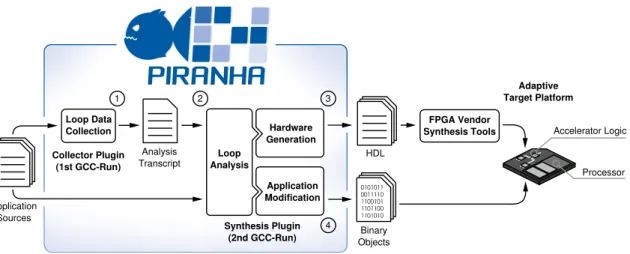
As mentioned in Section 1.2, the idea behind PIRANHA is to provide a transpar-ent tool-flow for software programmers in order to considerably lower the transpar-entry barrier for hardware development. Hence, the selection of suitable accelerators as well as the integration of accelerators into the host system is completely auto-mated. PIRANHA consists of two separated GCC-plugins collectively performing four processing steps. Figure 2.11 gives an overview of the tool-flow and its processing steps.
1. Theloop data collectionperforms a whole-program analysis and collects in-formation about all loops of the program. This step must be carried out in a separate compilation run in order to ensure that all files of the program can be analyzed. Thus, it is solely implemented within the first plugin. The result of this run is an analysis transcript of all loops within the program.
2.9. GCC PIRANHA 45 Hardware Generation 0011110 1100101 1101100 1101010 0101011 Loop Data Collection Loop Analysis Application Modification FPGA Vendor Synthesis Tools Analysis Transcript Processor HDL Accelerator Logic Collector Plugin (1st GCC-Run) Synthesis Plugin (2nd GCC-Run) Adaptive Target Platform Binary Objects Application Sources 1 2 3 4
Figure 2.11: GCC plugin-based HLS work-flow for configurable architectures
2. Theloop analysis is performed as a first step from the second plugin during the second compilation run. Its task is to analyze each loop of the source code by using the gathered data from Step 1. Besides this information, it analyzes the feasibility of hardware generation and uses a cost model to estimate the speedup of loops with respect to the target platform.
3. The hardware generationperforms the HLS for loops that were selected in
the previous step. The result of this step is a hardware description of the generated accelerators.
4. The application modification adapts the original software code in order to
integrate the hardware accelerator. According to the target platform, ad-ditional C code is generated to perform the communication between host processor and accelerator interface. Afterwards, the whole application is translated and linked to generate a program binary.
GCC PIRANHA invests substantial effort to analyze the application in order to identify suitable code sections. For most of the existing HLS approaches, this task is assigned to the system developer, which may lead to better overall results but also to a much higher entry barrier for the user of the system. Hence, GCC PIRANHA has taken a completely new direction for HLS tool-flows. It works on whole applications and requires neither program rewriting nor special annotation or language features.
46 CHAPTER 2. HLS FOR CONFIGURABLE SYSTEMS
2.9.3 Runtime Work-Flow
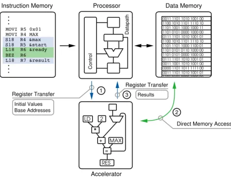
After generating a modified binary file in Ex
![Figure 2.4: Altera OpenCL hardware architecture [7]](https://thumb-us.123doks.com/thumbv2/123dok_us/1079393.2643660/34.892.186.728.772.1077/figure-altera-opencl-hardware-architecture.webp)
![Figure 2.10: LegUp design-flow [17]](https://thumb-us.123doks.com/thumbv2/123dok_us/1079393.2643660/43.892.169.712.503.715/figure-legup-design-flow.webp)
![Figure 3.1: Xilinx Artix FPGA layout [125, 113]](https://thumb-us.123doks.com/thumbv2/123dok_us/1079393.2643660/55.892.122.760.179.699/figure-xilinx-artix-fpga-layout.webp)
![Figure 3.4: SpartanMC memory Architecture [139]](https://thumb-us.123doks.com/thumbv2/123dok_us/1079393.2643660/60.892.140.774.181.814/figure-spartanmc-memory-architecture.webp)
![Figure 3.5: SpartanMC tool-flow [139]](https://thumb-us.123doks.com/thumbv2/123dok_us/1079393.2643660/61.892.152.729.601.1088/figure-spartanmc-tool-flow.webp)