Power Generation Using Rural Cooking
Method
Keerickal Jithin Abraham1, Prof. M. M. Jadhav2
P.G. Student, Department of Electronics & Telecommunication, Sinhgad College of Engineering Pune, India1
Professor, Department of Electronics & Telecommunication, Sinhgad College of Engineering Pune, India2
ABSTRACT: In rural areas, there are a lot of excess heat energy wasted due to the method of cooking by burning wooden logs. The heat energy is any how getting wasted into the atmosphere. It is not stored. The proposed system generates energy to charge rechargeable battery from the heat energy obtained by rural cooktop(chula). The stored energy is further utilized for providing electricity. In this system, a hybrid mechanism stirling engine and solar panel is used to generate energy.
KEYWORDS: Electricity generation, Excess heat, Heat recovery
I. INTRODUCTION
Awareness of climate change and the threat of rising energy prices have resulted in increased attention being paid to energy issues. However, this option has not been fully investigated. Now-a-days, there are lot of load shedding going on in many areas in India. Apart from that rising price of electricity is also a problem.
The scheme contributes a bit for the solution to the rising problems faced in our country. A method based on which electricity can be generated at home itself and use it for home appliances is discussed in this proposal. This will help the areas where electricity cannot reach easily. The system is a prototype of how can the naturally available resources can be used for electricity generation. Since it is a prototype, it may not help any house to generate so much of electricity that it can even operate heavy power consuming electrical devices. But this idea can be implemented later on a larger scale for heavy power consuming devices as well.
The paper deals with generation of current by the heat generated from a rural chulha as well as a solar panel. Thefirst part of this system consists of the hot air from the chulha sent into a cylinder of the Stirling Engine. The hot air at the base of the cylinder causes the piston to rise while the cold air moves it downwards. This pumping of the piston in turn results in the rotation of a fan which consists magnets. The rotation of these magnets generates a magnetic field. The coils in the generator, which is placed in front of the fan, induce electric current due to the change in the magnetic flux. Here the system is also integrated with solar panel.. This will result in more power generation.
II. RELATED WORK
explosions taking place. Because of this, Sterling engines are very quiet. The Sterling cycle uses an external heat source, which could be anything from gasoline to solar energy to the heat produced by decaying plants. No combustion takes place inside the cylinders of the engine. The Sterling engine uses the concept of Sterling cycle. In [3] author says Solar energy availability is never guaranteed and differs from places to places depending upon the location of the users as well as upon the timing of the day. Solar energy depends upon the very obvious, given time of any day and also prevailing weather conditions. The meteorological departments provides with constant real time updates of the weather and therefore their predictions can be used to for further strategic planning activities that requires solar energy. In[7] author says Stirling engines work using the heat energy as the energy input and are based on the Stirling cycle. It is proposed to develop a Stirling engine for a 1.5 kWe electrical output. A receiver for absorbing heat from solar concentrator or a flame will also be developed as an integral part of the engine. The heat available is expected to be at around 750 K. The engine will be tested and characterized in the laboratory using gas or electrical heaters. The estimated thermal efficiency of Stirling engine is expected to be around 37 %.
III.PROPOSED SYSTEM ARCHITECTURE
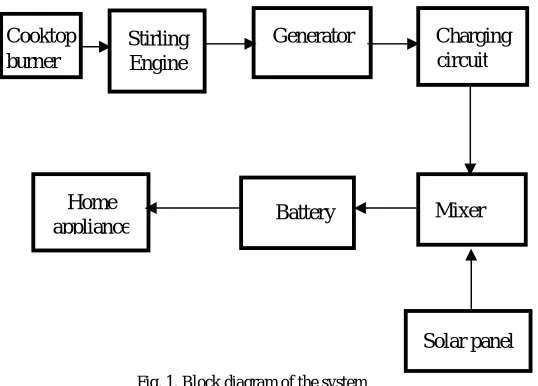
The proposal as shown if fig. 1 is a hybrid of stirling engine generator and solar panel electricity generator. Flame from the cook-top is directed to Stirling engine generator. Heating up of stirling engine The Stirling engine piston is coupled with fan-magnet setup creating change in magnetic field. This will result in generation of AC current in generator-coil. The charging circuit consists of a bridge rectifier converting AC to DC
Fig. 1. Block diagram of the system
Solar panel consist of a motor driver setup due to which it will rotate automatically to the direction from where sunlight comes more intensely. A forward biased PN junction diode is connected to avoid reverse current flow towards The current from solar panel and generator coil are given directly to the battery with the help of a simple mixer. As there is a possibility of solar setup current entering the stirling engine circuitry, A diode is connected to the stirling at the joint of stirling engine circuit with solar circuitry in order to avoid reverse flow of electric current.
The Solar Panel is mount such that it can rotate in the direction where sunlight is more. For the same, Light sensors are used on both sides and the output from light sensors are directed into motor driver IC which controls the DC motor.
Stirling Engine
Generator Charging circuit
Battery Home
appliance Cooktop burner
IV.SYSTEM IMPLEMENTATION
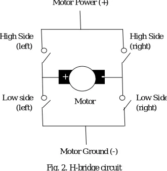
DC motor has been used to rotate solar panel according to the direction of sunlight for better response. Photo transistor has been used for this purpose connected to motor driver IC L293D which is controlled by AT89C2051 microcontroller programmed accordingly. Rotation of DC motor can be adjusted with the help of H-bridge circuit. Basic H-bridge circuit has four switches as shown in fig. 2, connected to the DC motor. Functioning of H-bridge is shown in table.1.
High Left
High Right
Low Left
High Right
Description
On Off Off On Runs clockwise Off On On Off Runs
anticlockwise On On Off Off Stops
Off Off On On Stops Table. 1. Truth table of H-bridge circuit
Motor driver IC l293d controls DC motor with reference to the input given to it by AT89C2051. Fig.2. shows the logic switch diagram of H-bridge circuitry.
Fig. 2. H-bridge circuit
Components which are mainly used in the proposed system are as follows :
A. Bridge Rectifier
It is used to convert AC current to DC current. Here in the proposed system, bridge rectifier is a part of charging circuit where the conversion and charging of battery is done.
B. Diode
PN junction Diode connected in forward bias avoiding reverse flow of current with a depletion layer of upto 2µm and knee voltage of upto 0.7V.
C. Stirling engine
Motor Power (+)
High Side (left)
High Side (right)
Low side (left)
Low Side (right)
Motor Ground (-) Motor
-D. Solar panel
Solar panel which is also used to generate electricity simultaneously is mounted with a DC motor controlled by a motor driver IC l293d.
E. Motor driver IC
Here system is using L293D which is a typical Motor driver or Motor Driver IC. This allows DC motor to drive on either direction. This L293D is a 16-pin IC which can control a set of two DC motors simultaneously in any direction. But the system will be using it only for a single motor.
F. AT89C2051
This microcontroller has been programmed to take input from DC L14G2 NPN phototransistor which converts the incident light energy into electric response and control the motor driver IC such that L293D rotates motor the motor according to the direction of incoming light
G. Battery
The system is using 4 batteries each of 2500mAh which can be charged upto 1.2V each. Batteries are connected in series with each other. The series combination offers a rating of 2500mAh/4.8V.
V. RESULTS AND DISCUSSION
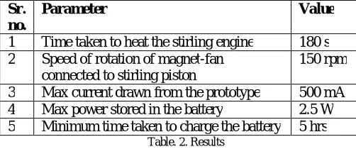
As a result, we generate power with the help of stirling and solar panel. Following table will help us understand the readings obtained from the prototype.
Sr. no.
Parameter Value
1 Time taken to heat the stirling engine 180 s 2 Speed of rotation of magnet-fan
connected to stirling piston
150 rpm
3 Max current drawn from the prototype 500 mA 4 Max power stored in the battery 2.5 W 5 Minimum time taken to charge the battery 5 hrs
Table. 2. Results
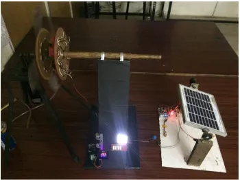
Fig. 3. Complete setup
VI.CONCLUSION AND FUTURE WORK
This system can be helpful to find a permanent solution for problem faced by rural areas where electricity is not available or affordable. I have found an alternative to convert heat energy from cooking stove into electrical energy. This will enlighten houses during night time which doesn’t have electricity connection.
As the designed system is only a prototype, the power generated is not sufficient to run all devices in the house. But this idea can be used in future to build a bigger model with power deliverance at a larger scale to practically eradicate the electricity crisis faced in many rural areas in India. This can be the future scope to this project.
REFERENCES
1. AnjumShahed Md. Abu Sufian, Muhammad Ahsan Ullah , DurjoyBaidya “Design of a Stirling Engine to Generate Green Energy in Rural
Areas of Bangladesh,” IEEE 2nd International Conference on Green Energy and Technology, September 2014 2. R.Aishwarya, K.DhivyaBharathi- “Solar Powered Stirling Engine for Self-Generating Electricity,” 2011
3. Md. Shahzada Chowdhury & Kurt Kornbluth, “a study on the stirling generator: producing bioelectricity,” daffodil international university of science and technology, vol. 1, january 2006
4. ShreyanshKakadiya and Ronak Jain “Solar Architect - Intelligent Recommendation Engine for Solar Energy Battery Use”IJIACS ISSN 2347 – 8616 Volume 4, Issue 11 November 2015
5. Sastry, E.V.R., “Village electrification programme in India”, Third World Conference on Photovoltaic Energy Conversion, Osaka, Japan, May 11-13, 2003.
6. Sawsan A. Mahmoud*, Basma S. Mohamed, “Study on the Performance of Photogalvanic Cell for Solar Energy Conversion and Storage” IJES-10, 24 feb,2015.