ISSN (Print) : 2320 – 3765 ISSN (Online): 2278 – 8875
I
nternational
J
ournal of
A
dvanced
R
esearch in
E
lectrical,
E
lectronics and
I
nstrumentation
E
ngineering
(An ISO 3297: 2007 Certified Organization)
Vol. 5, Issue 4, April 2016
Three Level Cascaded STATCOM for
Controlling Unbalanced Loads Using
Sequence Components
Dr. D V VV CH Mouli1, Suraj Kumar Singh2
Assistant Professor, Dept. of EEE, Hindustan University, Chennai, Tamilnadu, India1
PG Student [PSE], Dept. of EEE, Hindustan University, Chennai, Tamilnadu, India2
ABSTRACT: Multilevel inverters are used to increase the voltage level with less harmonics. This advantage can be utilized in designing STATCOM connected to the grid. High load applications used large amount of lagging loads, STATCOM should be capable to use as the VAR compensation in wide range for reactive load compensation. The dc-link voltages of the inverters are regulated at different levels to obtain multi-level operation. Multilevel inverter to be designed such that it produces higher voltage to fulfil the wide range of compensation simultaneously it should suppress the harmonics. So, in this paper necessary analysis and simulation to be observed to meet the above criterion. The simulation study is carried out in MATLAB/SIMULINK to predict the performance of the proposed scheme under balanced and unbalanced supply-voltage conditions with proposed unbalanced control.
KEYWORDS:Multi-level inverter, STATCOM, Total Harmonic Distortion (THD),Power Quality, Reactive Power Compensation, Voltage Source Converter (VSC),phase sequence, VAR compensation.
I.INTRODUCTION
In this paper the three level multi-level inverter is proposed. It is increasing the voltage level with less harmonics. It can also meet the wide range of reactive power compensation based firing angle control.
Normally 3-phase inverter produces 6n±1 level of harmonics. The harmonics[1] are further decreased if high number of pulses are used. Higher pulses required high switching frequency with switching losses. So, the multi-level inverter of 3-phase reduces the THD by increasing the number of levels. In multilevel inverter each level add with first level in certain percentage manner with some phase delay. The multi-level STATCOM uses the DC source for single level with using capacitors in other levels or using dc sources in all levels of the STATCOM . In the proposed system 3-level VSI is used for STATCOM. With this 3-level inverter by connecting to the unbalanced system, suitable controlling method using phase sequence components is also proposed. Different outputs are observed at different points for better analysis. Finally the stability of sensitivity function is also analysed. The STATCOM is proposed with new generation type using voltage source inverter. The multilevel inverter also quickly damp out the transient oscillations. So the multilevel inverter reduces the switching complications in complicated grid networks.
In this paper, the compensation using cascaded 3-level STATCOM is used with asymmetrical control with unbalanced condition.
II.CASDADED MULTILEVEL INVERTER
III. CASCADED THREE-LEVEL INVERTER-BASED MULTILEVEL STATCOM
Fig. 1 shows the three level cascaded multilevel inverter connected to the system with unbalanced loads. The unbalanced loads are resistive and inductive type. The inverters of the STATCOM are connected on the high-voltage (HV) side of the transformer with 2:1 ratio, and the low voltage (LV) side is connected to the power system. The dc-link voltages of the inverters are maintained constant and modulation indices are controlled to achieve the required objective. The THD at one phase of multi-level output is 3.17%.
Fig. 1 : Cascaded level connected to the system.
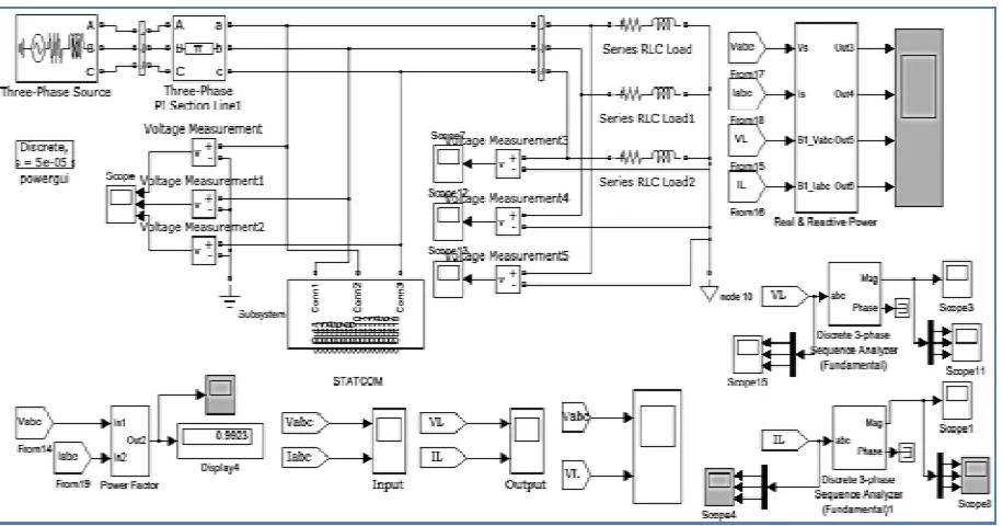
Fig 2. shows the Matlab circuit topology of the cascaded three level inverter based multilevel STATCOM .
Fig. 2: Matlab circuit for 3 level inverter STATCOM
ISSN (Print) : 2320 – 3765 ISSN (Online): 2278 – 8875
I
nternational
J
ournal of
A
dvanced
R
esearch in
E
lectrical,
E
lectronics and
I
nstrumentation
E
ngineering
(An ISO 3297: 2007 Certified Organization)
Vol. 5, Issue 4, April 2016
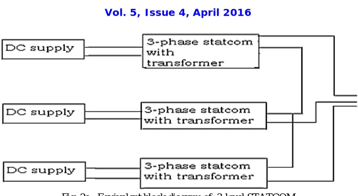
Fig. 2a: Equivalent block diagram of 3-level STATCOM
Ria+ Ldia/dt= Va-[ea1+ea2+ea3]
Rib + L dib/dt = Vb-[eb1+eb2+eb3]
Ric+ L dic/dt = Vc-[ec1+ec2+ec3] (1)
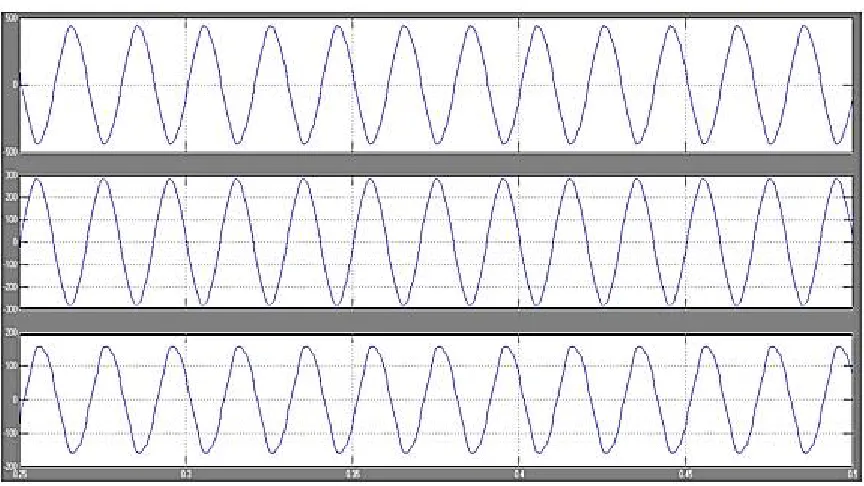
In fig 3,4 the multilevel output observed in each phase from matlab simulation are shown.
Fig. 4: System voltage output in each phase.
CONTROL OF REACTIVE POWER
The reactive power and real power both can be controlled using the 3-levelstatcom. The reactive power flow depends on voltage differences between statcom and system[5]. The real power flow depends up on angle between the statcom voltage and the system voltage. The STATCOM output voltage is controlled by modulating index provided with each inverter modulating index is within the linear range.
IV. UNBALANCED SYSTEM
The fig.5. shows the matlabsimulink model of multilevel inverter connected to the unbalanced system. The details of the multilevel inverter, grid generation and load details are given below.
Details of Multilevel inverter
DC value = 500V R=1Ώ C= 1uf
Details of System Parameters
Ph-Ph RMS value = 550V, f=50Hz
Details of Load Details
ISSN (Print) : 2320 – 3765 ISSN (Online): 2278 – 8875
I
nternational
J
ournal of
A
dvanced
R
esearch in
E
lectrical,
E
lectronics and
I
nstrumentation
E
ngineering
(An ISO 3297: 2007 Certified Organization)
Vol. 5, Issue 4, April 2016
Fig.5: Simulink model of transmission system with STATCOM
The table 1 shows the different sequence parameters comparison observed by connecting the STATCOM to the system using MATLAB. These sequence parameters are used for controlling the STATCOM under unbalanced condition. The unbalanced loads are causing excessive heating of the machines due to voltage fluctuations. These voltage fluctuations are controlled by STATCOM control using Sequence components. Considerable sequence components are generated for more variation of loads in each phase which leads to more unbalance. Sequence parameters are also more by connecting STATCOM to the system.
Table 1: comparison of system sequence parameters with and without STATCOM
Parameters of system without STATCOM at 50hz
Parameters of system with STATCOM at 50hz
• Sequence voltage
VL+ = 225V
VL- = 185V
VL0 = 0V
• Sequence voltage
VL+ = 240V
VL- = 195V
VL0 = 0V
• Sequence current
IL+ = 9.5A
IL- = 6.4A
IL0 = 0A
• Sequence current
IL+ = 11.8A
IL- = 8.2A
IL0 = 0A
• Voltage across load (peak values)
Vab = 410V
Vbc = 250V
Vca = 150V
• Voltage across load (peak values)
Vab = 440V
Vbc = 290V
Vca = 160V
• Power factor = 0.9822 • Power factor = 0.9924 • Current across line
Ia = 5.9A
Ib = 15.5A
Ic = 11A
• Current across line
Ia = 7A
Ib = 19A
SIMULATION RESULT
SEQUENCE VOLTAGE :Fig 6 shows the observed sequence voltages using matlab.A very small zero sequence voltage is developing across the load. The zero sequence amplitude is showing most random nature in both without and with STATCOM. The magnitude of positive and negative sequence voltage is increased by connecting STATCOM to the system. This is happening for sequence currents also as shown in fig.7.
Fig. 6a Fig. 6b
Fig. 6: Sequence voltages of the system without and with STATCOM
SEQUENCE CURRENTS :
Fig. 7a Fig. 7b
Fig. 7: Sequence currents of the system without and with STATCOM
ISSN (Print) : 2320 – 3765 ISSN (Online): 2278 – 8875
I
nternational
J
ournal of
A
dvanced
R
esearch in
E
lectrical,
E
lectronics and
I
nstrumentation
E
ngineering
(An ISO 3297: 2007 Certified Organization)
Vol. 5, Issue 4, April 2016
Fig. 8a Fig. 8b
Fig. 8: Power factor of the load without and with STATCOM
VOLTAGE AND CURRENT ACROSS LOAD (PEAK VALUES):-The load voltages and currents are showing high peak value by connecting STATCOM to the system with THD of load current is 3.65%
Fig. 9a Fig. 9b
CURRENT ACROSS LINE:
Fig. 10a Fig. 10b
Fig. 10 : current across the line without and with STATCOM
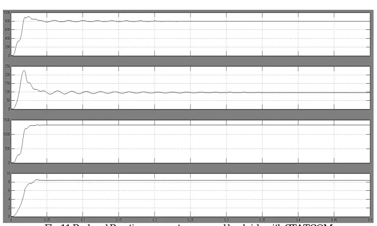
Fig.11 Real and Reactive power at source and load side with STATCOM
In above Fig 11. the source reactive power is showing overshoot with some settling time whereas load side only rise time is shown.
Comparison of DC currents without and with connecting of STATCOM to the system:
ISSN (Print) : 2320 – 3765 ISSN (Online): 2278 – 8875
I
nternational
J
ournal of
A
dvanced
R
esearch in
E
lectrical,
E
lectronics and
I
nstrumentation
E
ngineering
(An ISO 3297: 2007 Certified Organization)
Vol. 5, Issue 4, April 2016
STATCOM without connecting to the system STATCOM connecting to the system
Fig. 12 1st LEVEL STATCOM INPUT CAPACITOR CURRENT
Fig. 13 1st LEVEL STATCOM INPUT CURRENT
Fig. 15 2nd LEVEL STATCOM INPUT CURRENT
ISSN (Print) : 2320 – 3765 ISSN (Online): 2278 – 8875
I
nternational
J
ournal of
A
dvanced
R
esearch in
E
lectrical,
E
lectronics and
I
nstrumentation
E
ngineering
(An ISO 3297: 2007 Certified Organization)
Vol. 5, Issue 4, April 2016
Fig. 173rd LEVEL STATCOM INPUT CURRENT
In all the above simulation output figures the X –axis is time scale in seconds, Y- axis is in corresponding parameters with its units.
PHASE SEQUENCE CONVERSION:
The symmetrical components can be used to determine any unbalanced current or voltage (Ia, Ib, Ic or Va, Vb, Vc) as
follows:
CURRENT VOLTAGE
Ia = Ia1 + Ia2 + Ia0 Va = Va1 + Va2 + Va0
Ib = a2Ia1 + aIa2 + Ia0 Vb = a2 Va1 + aVa2 + Va0
Ic = aIa1 + a2Ia2 + Ia0 Vc = aVa1 + a2Va2 + Va0
Iabc = 7.0000 -89.9420 Vabc = 620 0
19.0000 -209.9710 95 -120
14.0000 -328.0970 48 -240
The sequence currents or voltages from a three-phase unbalanced set with STATCOM can be calculated using the following equations:
Zero Sequence Component:
Ia0 = ⅓ (Ia + Ib + Ic) Va0 = ⅓ (Va + Vb + Vc)
Ia0 = 3.6313∟114.7855 Va0 = 183.3361∟-4.2440
Positive Sequence Component:
Ia1 = ⅓ (Ia + aIb + a2Ic) Va1 = ⅓ (Va + aVb + a2Vc)
Ia1 = 13.3317∟-89.3100 Va1 = 254.3333∟0.0000
Negative Sequence Component:
Ia2 = ⅓ (Ia + a2Ib + aIc) Va2 = ⅓ (Va + a2Vb + aVc)
Similarly
Ib1 = 13.3317∟150.69 Vb1 = 254.3333∟240
Ib2 = 3.3285∟185.7157 Vb2 = 183.3361∟124.2440
Ic1 = 13.3317∟30.69 Vc1 = 254.3333∟120
Ic2 = 3.3285∟305.7157 Vc2 = 183.3361∟244.2440
Where Ia0=Ib0=Ic0 Va0=Vb0=Vc0
V. SEQUENCE CONTROLLING OF STATCOM
The Figure18. shows the firing angle control of the multi-level STATCOM using modulation index variation using
simultaneous sequence voltage, dq voltage , αβ voltage sensing with proper time delay
The dq phase sequences are obtained from phase sequence voltages[6]. Whereas in balanced loads ,dq transformation is obtained from phase voltages. Compared to the zero sequence component, Negative sequence component gives the significant contribution for controlling STATCOM.
Fig. 18 Sequence controlling of the STATCOM
Vq+ 0 - √
- -√ 2cosθ 0 0
Vd+
0 -√ - √ - -2sinθ 0 0 1 1 1 Va1
Vq- = 0 - - √
- √ 0 2cosθ 0 a2a 1 Va2
Vd- 0 √
- -√ - 0 -2sinθ 0 a a2 1 Va0
Vq0 0 0 0 0 0 2cosθ
Vd0 0 0 0 0 0 -2sinθ
Vq+ jsinθ+cosθ -jsinθ+cosθ 0
Vd+ - sinθ+( +j)cosθ - sinθ+( -j)cosθ sinθ+ cosθ Va1
Vq- = -jsinθ+cosθjsinθ+cosθ 0 Va2
Vd- - sinθ+( +j)cosθ - sinθ-( -j)cosθ sinθ+ cosθ Va0
Vq0 0 0 2cosθ
ISSN (Print) : 2320 – 3765 ISSN (Online): 2278 – 8875
I
nternational
J
ournal of
A
dvanced
R
esearch in
E
lectrical,
E
lectronics and
I
nstrumentation
E
ngineering
(An ISO 3297: 2007 Certified Organization)
Vol. 5, Issue 4, April 2016
VI. REACTIVE POWER SENSITIVITY TRANSFER FUNCTION
Siq = - ω[id] - iq + [Vq – (eq1 + eq2 + eq3)]
Sid = - id+ ω[iq] + [Vd – (ed1 + ed2 + ed3)]
Siq = - ω[id] - iq + [Vq~]
Sid = - id+ ω[iq] + [Vd~]
Sid + id= ω[iq] + [Vd~]
(s + ) id= ω[iq] + [Vd~]
id =
( ) iq + ( ) [Vd~]
Siq = -ω [( ) iq + ( ) (Vd~)] - iq + [Vq~]
Siq = - ( ) iq - id - ( ) [Vd~] + [Vq~]
if Vd~ = 0
Siq + ( ) iq + iq = [Vq~]
Tsen│vd~ = iq/ Vq~ = [
]
= ( ) (5)
For multilevel inverter , L=0.596h,ω=314rad/sec ,R=0.0149Ώ
Bode plot and Root locus of sensitive function:- From the bode plot and root locus with all values of K, it is observed that the sensitivity function shows the stable response.
Fig. 20 Root locus of the sensitivity function
VII.CONCLUSION
Instead of high number of pulses of 3-phase inverters, the multilevel inverter with proper switching sequence also reduces the THD and gives better unbalanced control with sequence components. Sequence component magnitudes are increased by connecting the STATCOM to the system. The sensitivity of transfer function can also be used for controlling the STATCOM under balanced loads .
REFERENCES
[1] K.K Mohapatra, K.Gopakumar, V.T.Somasekar, “ A harmonic elimination and suppression scheme for an open-end winding induction motor drive “ IEEE Trans. Industrial electronics 2003 ,vol.50, no.6 , pp 1187-1198
[2] N.N.V. SurendraBabu , B.G.Fernandes,” Cascaded two level inverter –based Multilevel STATCOM for higher –power Application “ IEEE Trans. Power delivery ,vol.29,no.3,pgs : 993-1001, March 2014
[3] N.N.V. SurendraBabu , D.Apparao, B.G.Fernandes,” Asymmetrical dc link voltage balance of a cascaded two level inverter based STATCOM “ proc. IEEE TENCON, 2010,PP.483-488
[4] Ranjan A.K., Bhaskar D.V ,Parida .N ,” Analysis and Simulation of cascaded H-Bridge multilevel inverter using level shift PWM technique “ IEEE Trans. Power Electronics
[5] N.G.Hingorani, L.Gyugyi,” Understanding FACTS “ , Newyork ,IEEE press,2001