Design of a Compact Two Element MIMO Antenna System
with Improved Isolation
Kamili J. Babu1, *, Rabah W. Aldhaheri2, Mohammed Y. Talha2, and Ibrahim S. Alruhaili2
Abstract—A novel compact two-element MIMO (Multiple Input Multiple Output) antenna system operating from 6.1–7.8 GHz is proposed for wireless applications. The developed antenna system resonates at 6.8 GHz frequency, giving an impedance bandwidth of 25% (based on S11 < −10 dB). An efficient technique is proposed to reduce the mutual coupling developed in the antenna system by employing a simple microstrip patch element in between the antennas. Using the proposed method, the mutual coupling is reduced to around −33 dB at the resonant frequency and maintaining the overall mutual coupling less than −20 dB in the operating band. The experimental models are developed for both the MIMO systems, i.e., without and with patch element between the antennas and the results are compared with simulated results. Also, Envelope Correlation Coefficient (ECC) between the two antennas is calculated and compared.
1. INTRODUCTION
The current 4G technology requires the communication systems that can handle larger data rates with high speed, quality of transmission, and accuracy. In the present advanced wireless communication scenario, Multiple Input Multiple Output (MIMO) technology plays a key role to meet the requirements of high quality and high data rate communication systems [1]. However, it is a big challenge to keep multiple number of antennas within a small and compact space due to the mutual coupling developed in between antenna elements. This mutual coupling arises due to the interaction of radiations from closely spaced antennas and also due to the surface currents flowing on the ground plane [2]. The physical causes of the mutual coupling between a pair of identical microstrip antennas are studied and analyzed in [3]. The impact of mutual coupling on channel capacity of a MIMO system is discussed in detail in [4].
The current research on MIMO antenna design is mainly focused on mitigating the effect of this mutual coupling and investigating various efficient techniques to reduce it. Surface current distribution is one of the key factors in deciding the amount of mutual coupling between the antennas. By altering the ground surface current distribution, a MIMO system with reduced mutual coupling is developed in [5]. Employing EBG structures on the ground plane is another technique to reduce the mutual coupling between MIMO elements [6–8]. However, this method is complicated and occupies larger areas in the system. In [9], the mutual coupling is minimized by introducing a defect on the ground plane between the antennas. In [10], the mutual coupling has been reduced significantly at the cost of some complicated structure at the ground plane. However, the system suffers from radiation pattern degradation. In [11], the mutual coupling between a pair of simple rectangular patch antennas is reduced by introducing a simple U-section in between the antennas, however with less impedance matching.
Received 3 July 2014, Accepted 5 August 2014, Scheduled 12 August 2014
* Corresponding author: Kamili Jagadeesh Babu (jagan [email protected]).
In the present investigation, the mutual coupling is reduced by introducing a simple microstrip element in between the two antennas. The inclusion of a rectangular microstrip patch between the antennas reduced the mutual coupling by more than −33 dB, without affecting other characteristics of the antenna system like impedance bandwidth, return loss and the radiation pattern. The design of the basic antenna system is discussed in Section 2 and the antenna system with reduced mutual coupling is presented in Section 3. All the simulations are carried out using CST simulator. The simulated and measured results are found in good agreement.
2. DESIGN OF BASIC MIMO ANTENNA SYSTEM
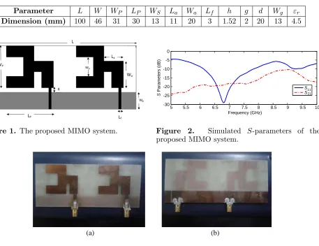
The geometry of the proposed MIMO antenna system is shown in Figure 1. The antenna is a printed monopole antenna with reduced ground plane. The area of each antenna is 30×46 mm2 and area of the proposed MIMO system is 100×46 mm2. The edge to edge separation between the antennas in the MIMO system is taken as d = 20 mm (0.45λ0). The antennas are fed with a microstrip feed with dimension Lf = 3 mm as shown in Figure 1. The final parameters of the antenna are listed in Table 1. The basic idea behind the shape of the antenna system is derived from popular E-shaped patch antenna [12] and the dimensions of the antenna are optimized so that it resonates at 6.8 GHz frequency in the 6.1 GHz to 7.8 GHz band. This operating band is suitable for many wireless applications in C band (4 to 8 GHz) and specifically for Location Tacking Applications for Emergency Services (LAES) as specified by Electronics Communications Committee (ECC). The antenna system is developed on a FR4 substrate of permittivity εr = 4.5, loss tangent of 0.02 and having a thickness of h = 1.52 mm.
Table 1. Dimensions of the proposed MIMO system.
Parameter L W WP LP WS La Wa Lf h g d Wg εr Dimension (mm) 100 46 31 30 13 11 20 3 1.52 2 20 13 4.5
Figure 1. The proposed MIMO system.
5 5.5 6 6.5 7 7.5 8 8.5 9 9.5 10
Frequency (GHz)
S S1121
-30 -25 -20 -15 -10 -5 0
S
Parameters (dB)
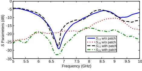
Figure 2. Simulated S-parameters of the proposed MIMO system.
(a) (b)
5 5.5 6 6.5 7 7.5 8 8.5 9 9.5 10 Frequency (GHz)
S Simulated S Simulated S Measured S Measured S Simulated S Measured22
22 21 11 21 11 -35 -30 -25 -20 -15 -10 -5 0 S Parameters (dB)
Figure 4. Comparison of simulated and measured S-parameters of the proposed MIMO system.
Figure 5. Surface current distribution of the proposed MIMO antenna system.
The selected substrate permittivity value is comparatively high so that the surface waves are minimized giving improved isolation between the antennas. The antenna resonant behavior is optimized for the ground dimension Wg = 13 mm using CST simulator.
The simulated S-parameters of the proposed MIMO antenna system are shown in Figure 2. The antenna system gives return loss around 30 dB at the resonant frequency 6.8 GHz, with an impedance bandwidth of 25% in the frequency band 6.1 GHz to 7.8 GHz. In the present study, the main focus is on mutual coupling and is found to be −19 dB at the resonant frequency. The antenna system is fabricated and the measurements are carried out using the Agilent Vector Network Analyzer N5230A. The fabricated prototype is shown in Figure 3. The comparison between the simulated and measured results is shown in Figure 4. The surface current distribution of the proposed MIMO system is shown in Figure 5.
3. DESIGN OF MIMO ANTENNA SYSTEM WITH IMPROVED ISOLATION
In the previous section, the developed antenna system gives an isolation of 19 dB between the two antennas. In this section, the proposed technique gives an isolation of 33 dB, i.e., improving the isolation by around 14 dB. A proper design of the extra element in between the antennas creates an indirect signal coming via the extra coupling path that opposes the signal going directly from element to element. If the two signal strengths are comparable, the two signals add up destructively resulting in the reduction of mutual coupling. In [11], the authors achieved the reduction in mutual coupling by introducing a U-section in between the elements of the array system, with a separation of 0.6λ0 between the antennas. However, the work is limited to the analysis of a simple rectangular patch array system with narrow bandwidth. In the present work, the reduction of mutual coupling is achieved by keeping a simple rectangular patch element in between the antennas as shown in Figure 6.
Figure 6. The proposed MIMO system with rectangular patch in between the antennas.
5 5.5 6 6.5 7 7.5 8 8.5 9 9.5 10
Frequency (GHz)
S w/o patch S w/o patch S with patch S with patch
11 21 11 21 -35 -30 -25 -20 -15 -10 -5 0 S Parameters (dB)
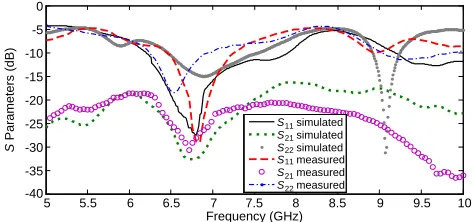
The dimension of the rectangular strip is optimized with the help of CST simulator and the value is taken as Ls= 3 mm. A comparison of the simulated S-parameters without and with patch in between
the antennas of the MIMO system is shown in Figure 7. From the Figure 7, it can be observed that the mutual coupling is around −33 dB at the resonant frequency and maintaining the overall mutual coupling less than −20 dB in the operating band. This means that by introducing the rectangular patch element in between the antennas, the mutual coupling is reduced by an amount of 14 dB. This improvement in isolation is better compared to the work discussed in [13], which achieved an isolation improvement of 12 dB for 0.5λ0 spacing. In [14], the authors achieved considerable amount of isolation using complex EBG structures with a separation ofλ0. In the present work, good isolation characteristics are achieved using a simple structure and for 0.45λ0 spacing. The photographs of the fabricated MIMO system with patch element in between the antennas are shown in Figure 8. The simulated and measured
S-parameters of the proposed MIMO system with patch in between the antennas are shown in Figure 9. The reason for the reduction of mutual coupling between the antennas and the basic idea behind arriving at the shape of the proposed antenna can be understood by analyzing the surface current distribution shown in Figure 10. The amount of mutual coupling between the two antennas in a MIMO system depends on the directions of the current flowing on the surface of the antennas. If the current flows in same direction on the adjacent sides of both the antennas, the mutual coupling is more. Similarly, if the currents are in opposite direction, the induced mutual coupling is minimized [15]. In the proposed MIMO antenna system, the surface currents on the right arm of the first antenna and on the patch element placed in between the antennas are flowing in opposite directions as shown in Figure 10, thus minimizing the mutual coupling.
The performance of the proposed antenna is further evaluated with the help of another important parameter known as Envelope Correlation Coefficient (ECC), which is defined using Eq. (1) [16]. This parameter is useful in estimating the diversity performance of a MIMO system. The ECC is calculated for both the MIMO systems, i.e., without and with patch element in between the antennas and is plotted in Figure 11. From the plot, it can be observed that the envelope correlation coefficient is very low at the resonant frequency, which indicates the good isolation between the two antennas in the MIMO system.
(a) (b)
Figure 8. Photographs of the fabricated MIMO array with patch in between the antennas. (a) Top layer. (b) Bottom layer.
5 5.5 6 6.5 7 7.5 8 8.5 9 9.5 10
Frequency (GHz) S simulated S simulated S simulated S measured S measured S measured
11 21 22 11 21 22
-40 -35 -30 -25 -20 -15 -10 -5 0
S
Parameters (dB)
Figure 10. Surface current distribution of the proposed MIMO antenna system with reduced mutual coupling.
5 5.5 6 6.5 7 7.5 8 8.5 9 9.5 10
Frequency (GHz) with patch without patch
0 0.05 0.1 0.15 0.2
Correlation Coefficient
Figure 11. Envelope correlation coefficient of the proposed two element MIMO system.
(a) (b)
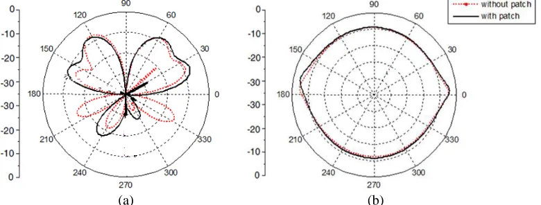
Figure 12. Radiation patterns of the developed MIMO systems at 6.8 GHz on (a)E-plane, (b)H-plane.
The obtained ECC value at the resonant frequency for the MIMO system without patch element is 0.012 and with patch element in between the antennas is 0.005 and these values are smaller compared to the ECC value obtained in [17], which is around 0.15. The measured radiation patterns of the developed MIMO antenna system without and with patch element between the antennas are shown in Figure 12.
ρ= |S
∗
11S12+S21∗ S22|2
1− |S11|2− |S21|2 1− |S22|2− |S12|2
(1)
4. CONCLUSION
In the present work, a novel two element MIMO system with improved isolation is proposed and physically realized. The mutual coupling in the developed MIMO antenna system is analyzed without and with patch element between the antennas. The MIMO system with patch element between the antennas is shown to improve the isolation by 14 dB. This MIMO antenna array resonates at 6.8 GHz with an impedance bandwidth of 25% in the frequency range 6.1 GHz–7.8 GHz and with a reduced mutual coupling of −33 dB at the resonant frequency and maintaining the overall mutual coupling less than −20 dB in the operating band. The developed MIMO system with reduced mutual coupling can be used in many wireless applications in C band.
ACKNOWLEDGMENT
REFERENCES
1. Foschini, G. J. and M. J. Gans, “On limits of wireless communications in a fading environment when using multiple antennas,”Wireless Personal Communications, Vol. 6, No. 3, 311–335, 1998. 2. Han, M. S. and J. Choi, “MIMO antenna using a decoupling network for next generation mobile application,” 9th International Symposium on Communications and Information Technology, ISCIT 2009, 568–571, 2009.
3. Nikolic, M. M., A. R. Djordevic, and A. Nehorai, “Microstrip antennas with suppressed radiation in horizontal directions and reduced coupling,”IEEE Transactions on Antennas and Propagation, Vol. 53, No. 11, 3469–3476, 2005.
4. Abouda, A. A. and S. G. Haggman, “Effect of mutual coupling capacity of MIMO wireless channels in high SNR scenario,” Progress In Electromagnetics Research, Vol. 65, 27–40, 2006.
5. Chou, H. T., H. C. Cheng, H. T. Hsu, and L. R. Kuo, “Investigations of isolation improvement techniques for multiple input multiple output (MIMO) WLAN portable terminal applications,”
Progress In Electromagnetics Research, Vol. 85, 349–366, 2008.
6. Yu, A. and X. Zhang, “A novel method to improve the performance of microstrip antenna arrays using a dumbbell EBG structure,”IEEE Antennas and Wireless Propagation Letters, Vol. 2, 170– 172, 2003.
7. Caminita, F., S. Costanzo, G. DiMassa, G. Guarnieri, S. Maci, G. Mauriello, and I. Venneri, “Reduction of patch antenna coupling by using a compact EBG formed by shorted strips with interlocked branch-stubs,”IEEE Antennas and Wireless Propagation Letters, Vol. 8, 811–814, 2009. 8. Farahani, H. S., M. Veysi, M. Kamyab, and A. Tadjalli, “Mutual coupling reduction in patch antenna arrays using a UC-EBG superstrate,” IEEE Antennas and Wireless Propagation Letters, Vol. 9, 57–59, 2010.
9. Kakoyiannis, C. G. and P. Constantinou, “Compact printed arrays with embedded coupling mitigation for energy efficient wireless sensor networking,”International Journal of Antennas and Propagation, Vol. 2010, 1–18, Hindawi, 2010.
10. Habashi, A., J. Nourinia, and C. Ghobadi, “Mutual coupling reduction between very closely spaced patch antennas using low-profile folded split-ring resonators,”IEEE Antennas and Wireless Propagation Letters, Vol. 10, 862–865, 2011.
11. Farsi, S., H. Aliakbarian, B. Nauwelaers, and G. A. E. Vandenbosch, “Mutual coupling reduction between planar antenna by using a simple microstrip U-section,” IEEE Antennas and Wireless Propagation Letters, Vol. 11, 1501–1503, 2012.
12. Yang, F., X.-X. Zhang, X. Ye, and Y. Rahmat-Samii, “Wide-band E-shaped patch antennas for wireless communications,”IEEE Transactions on Antennas and Propagation, Vol. 49, No. 7, 1094– 1100, 2001.
13. Chung, K. L. and S. Kharkovsky, “Mutual coupling and gain enhancement using angular offset elements in circularly polarized patch array,” IEEE Antennas and Wireless Propagation Letters, Vol. 12, 1122–1124, 2013.
14. Payandehjoo, K. and R. Abhari, “Highly-isolated unidirectional multi-slot-antenna systems for enhanced MIMO performance,” International Journal of RF and Microwave Computer Aided Engineering, Vol. 24, 289–297, 2014.
15. Mak, A. C. K., C. R. Rowell, and R. D. Murch, “Isolation enhancement between two closely packed antennas,”IEEE Transactions on Antennas and Propagation, Vol. 56, No. 11, 3411–3419, 2008. 16. Blanch, S., J. Romeu, and I. Corbella, “Exact representation of antenna system diversity
Performance from input parameter description,”Electronics Letters, Vol. 39, No. 9, 705–707, 2003. 17. Li, W., W. Lin, and G. Yang, “A compact MIMO antenna system design with low correlation from